Oh damn, of course yeah, I hadn’t thought that far ahead. Will turn it or at least make a walkable space at that end
1 Like
A perfect crown for posterity - we got there. 

X and Z steppers are all done with loctite. I’ll spare everyone the details but it involved a lot of cursing as the stepper dropped once I unscrewed a grub screw.
Starting on squaring. Rough pen squaring was about (edit - 18mm) difference between diagonals, a fair bit I assume, gonna re-do it a few times more accurately and see what we’re working with then hopefully can adjust as needed.
12 Likes
Small updates - I’m gonna need to remove both sides to troubleshoot an issue where I have a longer Y side distance-wise discussed here: Y axis - both are different lengths - how? - #7 by lowriderbuildth
I figure if I’m going to take it all apart to that level, I might as well get the strut plates done at the same time, saves me doing it all again. (I’ll get them cut out of 4mm alu - any potential downsides?)
I used the handy strut generator in the docs with 1389 length and 11.5 wing size for a full sheet built with 29.5 EMT, 7 braces.
–
1/8” Makita Collet
Another thing I wish I knew when starting out is that the Makita router has a 1/4” collet and not 1/8”. If you’re not US based it’s $50-80 after shipping just for the 1/8” collet since from what I can see they’re not widely made, only by specialist toolmakers or shops in the US since there’s no official Makita version for the 700 series routers. UK does have some though, not sure about EU. In the UK it’s 25+ quid for one still.. pricey little things.
It might be worth factoring this into your router decision if Makita and Dewalt or another brand are a similar price as I think Dewalt comes with 1/8”?
–
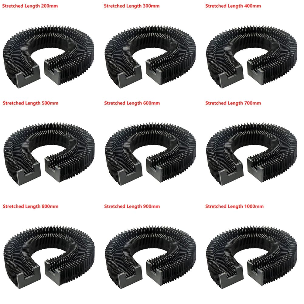
Got some random ads for linear rail bellows (to protect from dust and such). Could these be a thing for the LR?
1 Like
Nope, only the carbide 3D er11verion comes with both collet sizes
Nope.
1 Like
Are they easier to find for Dewalt? Surprised me how hard to get hold of they are for Makita, seems like a 1/8” collet would be a standard option.
110v?
220V (non-US) - no idea about different model versions for different voltages as I only have the Makita RT700C 220v version, but can’t see collets being different between them surely?
Nope.
Shame, they look kinda cool and would be helpful.
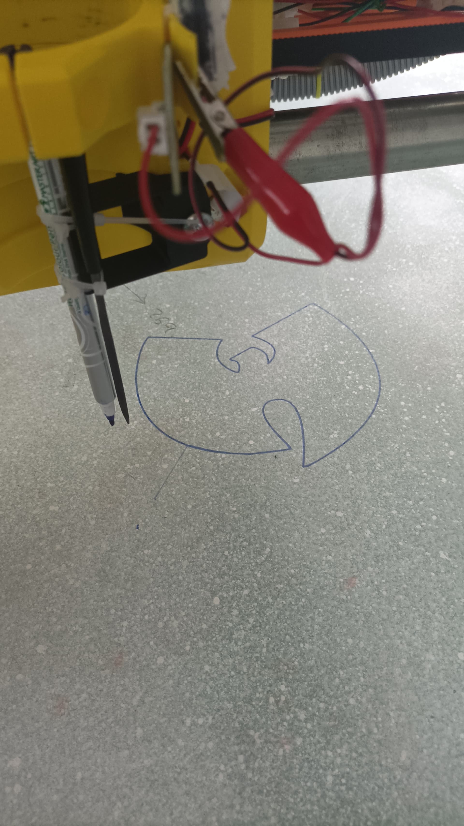
Another small victory - ran my first gcode.
Also hacked together a touchplate probe to use while pen drawing (a file that sits next to the pen).
Lots of small things to troubleshoot still - some funky noises on Z axis all the time, creaks and soft grinding almost, no idea what that could be. One side jams sometimes when reaching the bottom and skipping steps, requires a wiggle of the leadscrew to get it working again - if this is a common issue with a specific cause please let me know (my uneducated guess is the z screw nut not being level or the leadscrew itself leaning or twisted a bit), otherwise I’m just gonna do everything when the sides come off - troubleshoot the Y axis belt issues, put on struts, check everything is seated well, loctite pulleys, check all screws and check for binding etc.
Hopefully can catch everything in one big sweep and only have to take it apart the one time.
1 Like
If you fully tightened the screws that hold the Z screw nuts in place you might try backing them off a little to let them float. I have seen this mentioned somewhere on here. that may be the source of your noise.
2 Likes
They do make 1/4" shank endmills that end up in any size. You do not actually have to use a 1/8" collet to get an 1/8" tool. 1/8" shank tools tend to be cheaper but not always by a wide margin. And 1/4" shank to smaller cutter is technically a more rigid tool.
1 Like
Power down and take a very close look at both side and move them around.
Make sure you do not have the Z stub clamping screws in.
linear rails are parallel and smooth.
Best if your leadscrew nut does not touch the coupler so you might need to slide your coupler down further.
2 Likes
…and may cool better.
2 Likes
Happy new year guys, been a few weeks - plan is still to disassemble to fix issues and put on strut plates, but I’m at the point where I’m making test cuts and I think I’ll cut the strut plates soon enough.
Feed rates and everything else is a bit of trial and error right now, trying a few things.
I’m cutting HMR (High Moisture Resistance MDF style board), 1/8” 1F upcut bit. Using one of those cheap collet adaptors while waiting for a proper adaptor from Elaire, not sure how much difference that makes though.
Using the basic guide settings it was ok, but a bit squeaky and sort of resonance-y (not sure how to describe it) like the endmill or router was sorta squeaking and vibrating at a different rhythm.
I have upped DOC from 1mm to 6mm incrementally and feed rate I’ve been testing from 10-25mm/s. Makita is on 2.
6mm @ 20mm/s had a little bit of chatter or wobble or whatever it is, like very very slight rhythmic resistance you could see as the router moved, so figure it was too much.
Example finish (the one closest to bottom):

3mm @ 25mm/s cuts well without any noticeable chatter but the edges are a just a tiny bit rougher on the finished cuts. (No finishing pass, this is just a single straight peel cut at a single set depth)
Example:

.. so I’m gonna try a few different settings. I’m thinking the sweet starting spot is somewhere around 3mm DOC, 20-25mm/s and then next I’m gonna test from 2-3 on the Makita dial and see how it goes, and increase some stuff slowly.
Chips - I think it’s the nature of the material (glue-resin treated MDF style board) that results in ‘chips’ rather than dust because I get very little dust, just little curled pieces that resemble the pieces you get when using an eraser, those little rubber pieces that come off it.
So finding the ideal feed rate etc - Is it a little bit like photography and the exposure triangle where you sorta balance aperture/f-stop/shutter speed? There are limits to each I see, like ideally you don’t want to exceed say 2x bit diameter with doc(?) but am I right in thinking it’s the same concept, with rpm/doc/feed rate balancing each other out?
Also if anyone has any ball park settings they use for MDF (a similar material) that would be helpful too, just so I can see if I’m in the right area. HMR apparently has a little higher density, but is most similar to MDF.
I did find a few posts through search that indicate I’m probably being pretty conservative e.g someone posted about MDF:
“..cutting fairly well at 4.55mm DOC, 50mm/s feed rate and 24000RPM using my single flute 1/8" endmill.”
Cheers.
Oh, also, the router cutting is much quieter than I imagined. Still noisy, you’re not gonna be popular running one in a condo, but on level 2 and cutting HMR at least, it’s really not excessive.
2 Likes
I may be a newer member but I can help with this part! There’s a whole lot of going by vibes when it comes to feeds and speeds, but there doesn’t need to be… we can use math  DOC, feed rate (feeds), spindle rpm (speeds), and number of flutes equate to a chip size. You need to hit the ideal chip size for your material to avoid dulling your bit prematurely. Coincidentally, finding a good chip size also means you’ll have a nice cutting experience!
Check out my thread about adding this as a cheat sheet in Estlcam: Useful 'comment' section for tools even if you don’t use Estlcam, I’ve linked info there for calculating everything and given some examples of what I’ve done.
The biggest takeaway is to use single flutes, and that Dial 1 on the Makita (10k rpm) is all you really need. Also I fully recommend following Ryan’s philosophy of just doing it a little slower to ensure the project comes out well on the first try. You might spend hours dialing in the most ideal feeds and DOC, or you could just do like 6 mm DOC, 15 mm/s, 10k RPM (on a 1/8 single flute in plywood and MDF) on all of your projects and actually save time because it’ll all “just work” :). You CAN cut deeper, but then chip evacuation becomes impossible and your bit will cook as it recuts all the shavings. You CAN cut faster, but adding 5-10 mm/s to most jobs only saves a few minutes and opens you up to more risk.
Now if you’re going to manufacture and bulk produce stuff, you’d better try and eek out all the efficiency you can, but for making cool stuff for yourself and others? “Low and slow will work on the first go” can’t be beaten! …then again, I’m only confident in all of the aforementioned because of all the time I’ve spent experimenting, so you do you
3 Likes
Thanks, I actually found your post and used it as a reference after the docs settings. 
6mm seems iffy at every setting I’ve tried (including 6 mm DOC, 15 mm/s, 10k RPM) so I’ll probably keep it around 3mm and do several passes until i have a better understanding of everything and the strut plates are one.
I’ll try keeping the dial at 1, doc 3mm and just modify feed rate until it seems smooth, using the chart/calcs as reference.
Like you mentioned in the post, I have no idea what a good cut sounds like, except for some sounding a bit shaky or stuttery with the whole LR body or router, which I figure can’t be great, the initial docs settings were squeaky a little, and some are just consistent ‘normal’ sound that I can’t really hear a difference between, despite different settings.
2 Likes
Ahhh yes, with just the temporary strut plates my advice doesn’t really hold. Sorry for skipping over that important aspect! with the temporary strut plates you want to cut the plates ASAP so you can start having some real fun :). I’d go super low and slow, like 1 or 2mm DOC and maybe 5 mm/s to get them cut out. Slow and steady.
It can be tricky depending on your material. For example I used some 4ish mm plywood from Lowes and it’s so flimsy that it’s hard to keep down on the table. I eventually stapled it down, but double sided tape, or masking tape on the table and workpiece with super glue between the tape would also work well.
Since the machine is only ridged where the temp struts are, you want to be cutting as close to X minimum as possible. Meaning it may be helpful to cut one strut plate, remove it, and then reset the workpiece so the second plate is also cut as close to X minimum as possible. It can be a pain but it is fantastic learning experience, and we’re all here to help
1 Like
So there are a bunch of standards. The diameter of the endmill = D. Most manufacturers show settings in terms of 1D depth, sometimes 2D. More than 2D you need to know what you are doing. So, yes, between 3-6mm with a 1/8" endmill is pretty standard. If you are not slotting at all, you can go full depth, as we do for finishing passes.
yeah for most things we do 1-3 on the dial is perfect. Occasionally I will go higher but you can hear when it is needed.
You will learn it, it just takes time.
MDF is the hardest material to learn, it is very consistent so it is the safest (until you hit a rock), but things like natural wood, and plastic, you can hear and see the feeds and speeds, MDF you are just scraping out cuts and making dust.
1 Like
Oh and your cuts look perfect, in MDF you will always get fuzz at the tops.
In MDF not aggressive enough and you are going to get burning, too aggressive and it breaks end mills and has poor tolerances. There is a huge in between where you are doing just fine.
2 Likes
Thanks, that’s reassuring knowing I’m on the right track.
Once the strut plates are on and everything is set I’ll dive in a little deeper.
1 Like
I managed to cut the struts after a few attempts (mostly crashes of the gantry due to various rookie mistakes)
So in my joyful state after getting them cut out without issues I quickly took the core off and whole LR apart ready to mount the struts.. then realised the drilled holes by the gcode/ESTLCam are the bit diameter.. not the right size for the screws? And at one end they are not in the center of the tab opening, on both. The holes gradually move out from the tab position along the length of the strut.
Pictured is near one end. The other end of the front strut has close to middle holes and at the opposite end it’s far out.
Not sure what I did wrong there, but I’mma have to manually drill holes now instead I guess.
I just opened the gcode in a viewer to see if it was the actual file, and no - the file looks good. Holes in correct place. So why/how would it do them incorrectly? First thought is the LR is obviously not square or whatever, which I’ve had trouble with, but if that was the case, wouldn’t the tabs also have moved along with the drilled holes?
The strut itself looks perfect, perfect length, fits perfectly between both Y ends, just the holes are wrong.
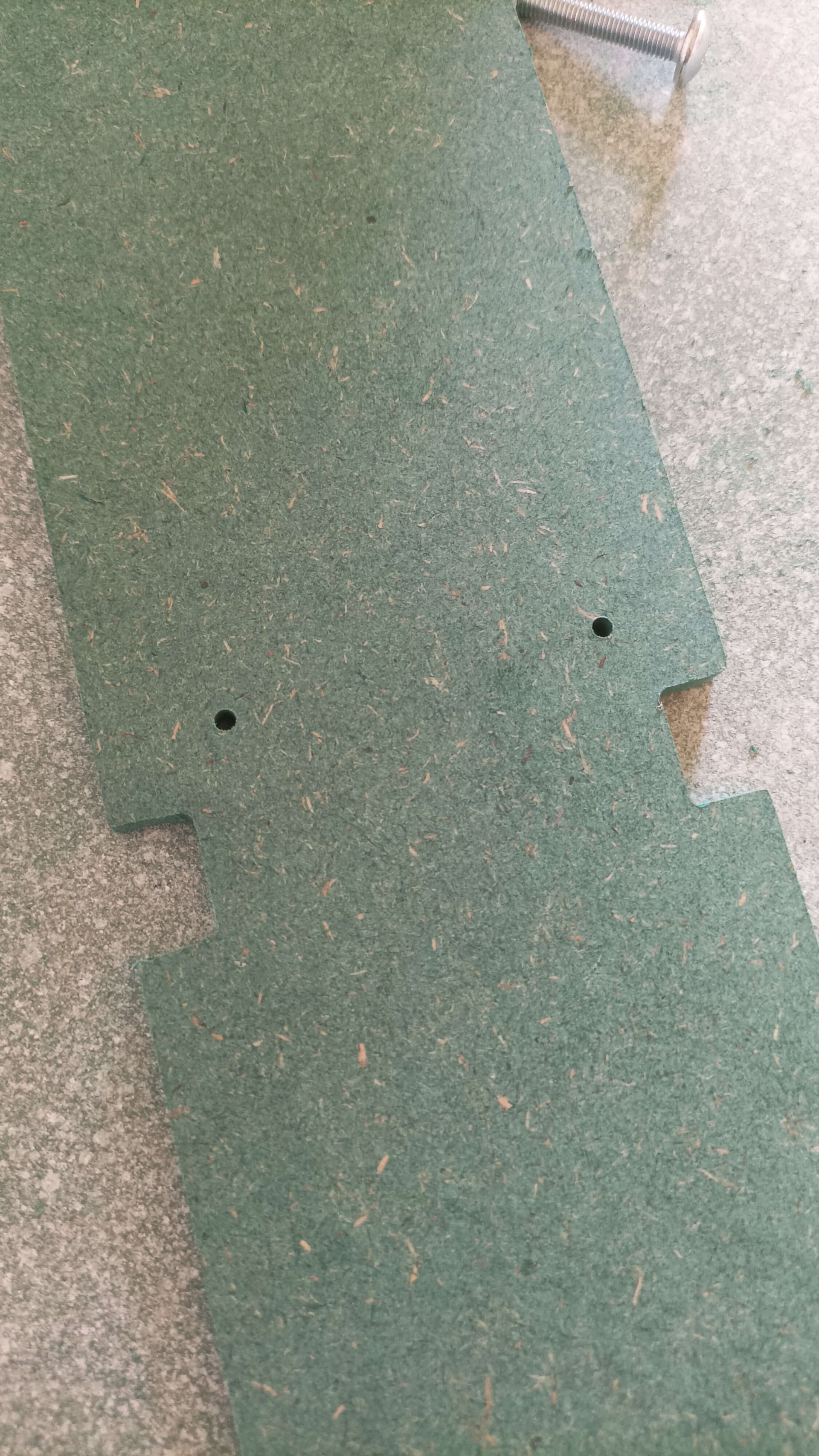
A longer view where you can see the hole position changing along the length.

Could this be because of the hole diameter being smaller?
Not sure how CAM and gcode works in the background, but if instead of drilling the full size hole, it’s just drilling bit diameter in the center, that extra missed mm or 2 could add up over time, where gcode or whatever is reading movements from the svg type path to the next ones rather than the drilled hole? That would explain the increasing movement from center over time. Not sure if I can explain it well, but could it be the culprit, something to do with the wrong drill diameter setting or highlighting the drill circle incorrectly in ESTLcam?