Hi guys, hoping to get the LR4 built and running here in Thailand.
I have no experience with CNC stuff, but I’ve built a few small projects in the past that are kinda similar, namely arcade machines and a virtual pinball table. I’m absolutely useless with tools and woodworking, that was always the worst/hackiest part of those builds for me (think Homer Simpson’s spice rack), so the idea of being able to design stuff and cut accurately with a CNC is appealing!
Funnily enough once they were built I barely played them and they’re still gathering dust today, but for months (nearly 9 months in the case of the VP machine) it consumed my life. Just working on a build/project was super enjoyable.
Big thanks to Ryan and everyone here for all the help and guides, I think I can manage it as there’s tons of good info.
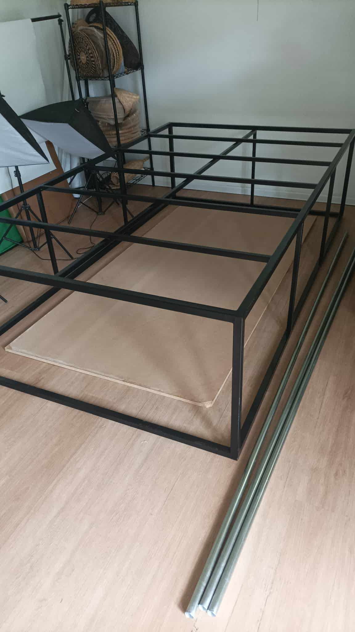
For now I’ve just been sourcing parts and making a little space in the outdoors room - I got a small metal frame half built by someone locally, gonna add some diagonal supports and get it a bit stronger, then whack some wood on top for a flat surface to work on.
Heat and humidity is gonna be a problem for sure so looking into ways to combat that now, and every other problem I’m gonna deal with as I come to it, same as every project.
Update on 3D printed parts - I remember it said no supports, am I seeing supports here? Is this going to be an issue with larger pieces like the core if so?
Also as mentioned in chat, apologies but I was told here/realised after I ordered that it was against licence to get someone to print them, it wasn’t too clear in the docs, but I did ask Ryan for permission for getting plates done locally since Thailand customs are extortionate.
I did state ‘Do not use supports’ when asking someone to print, but if they are supports and I’m gonna have problems (first of many I’m sure) I’ll just buy a 3d printer and do it myself I think - shoulda done that in the first place when I realised (too late) I could get a BambuLabs A1 for the same price as the parts
(I’d be lying if I said there wasn’t a little part of me disappointed I didn’t have an excuse and justification to the wife to buy a 3d printer though )
Nearly all parts are ready now so will be able to crack on with the build next week I think and will update more with ELI5 progress and pics for those who come after.
Ryan’s license does not permit paying someone to print parts for you. He will sell you (properly) printed parts at a very reasonable price (I bought printed parts for my Primo and LR2, even though I had a 3D printer already, even with international shipping, still reasonable.)
Ryan does provide the files so you can DIY, but someone else making money off of his designs is kind of a bummer. He does have resellers selling parts in the EU and completed machines, under license.
Anyway, you should be okay so long as you clean the support material well.
No worries, I mentioned that in the post, I didn’t realise until after when chatting and someone mentioned it, it wasn’t clear to me in the docs. I asked Ryan for permission for the alu plates which he kindly granted, I just didn’t know the 3d printing was the same until I’d already given the files.
The issue with Thailand isn’t so much shipping (though that does add a lot to the cost), but customs. Thai customs officers are notorious for adding obscene charges, to the point most people just avoid importing anything unless it’s something tiny from China that’s worth like $5.
I recommend checking the holes were the wires feed through the core, and the side plates. If it was printed with supports there might be support material blocking them. Just try to run some wires through to check. Good luck with your build.
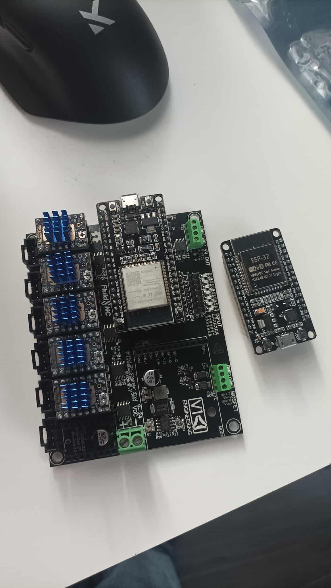
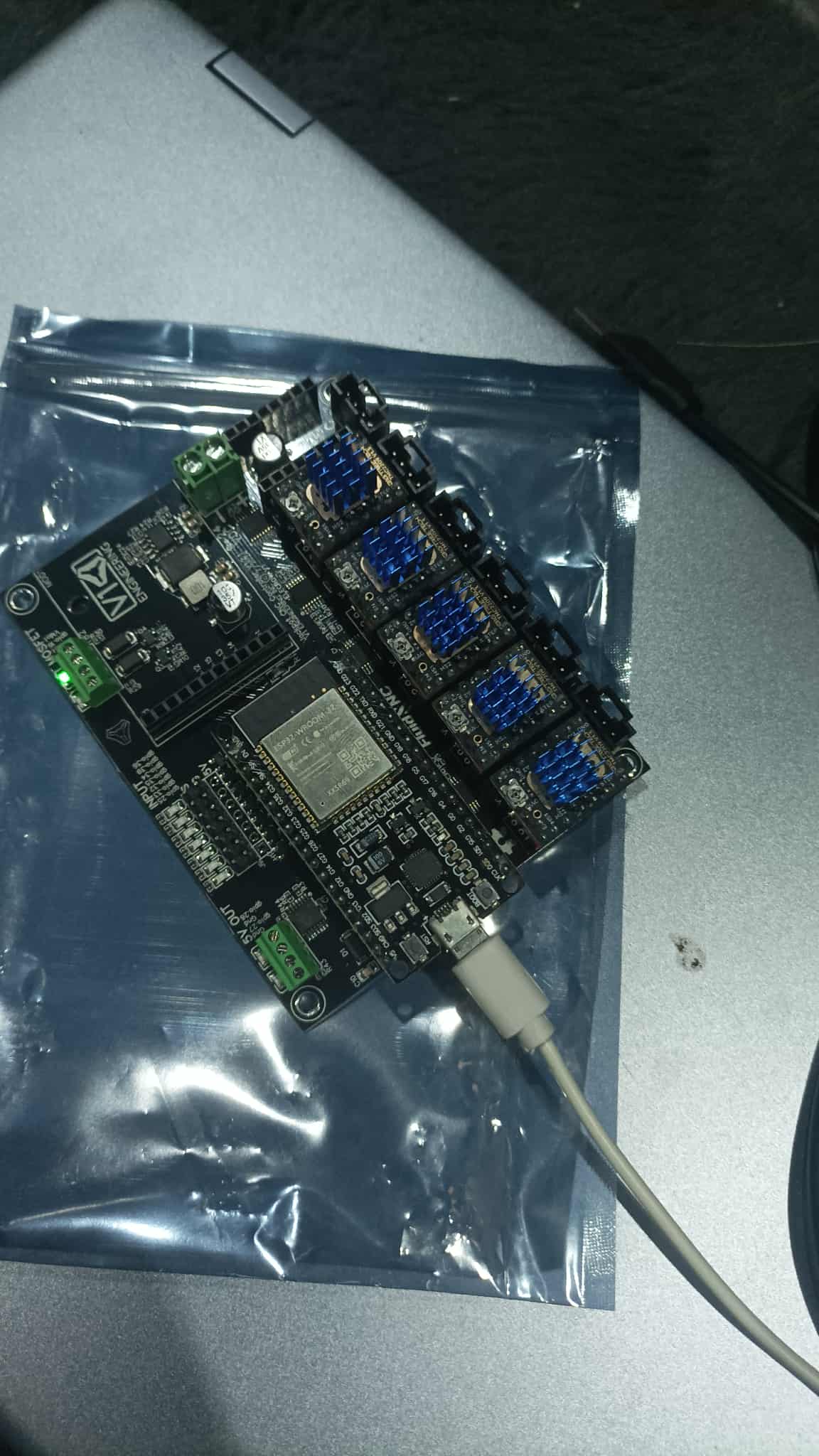
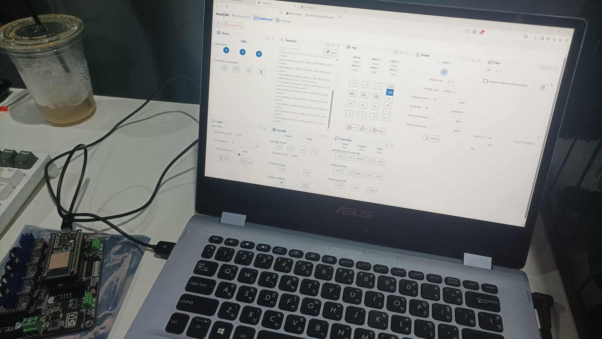
Set up the Jackpot board and FluidNC today following the handy guide from Hamish here: Setting up FluidNC
First, I had to put in the new ESP32 - the first one I bought was completely the wrong one (30pin instead of 38pin). I couldn’t find an Expressif branded one, but managed to find one that said ESP32-WROOM-32 on it at least, so was crossing my fingers it would work.
First issue I came to was not getting anything showing in Windows device manager. Quickly figured out this was down to rubbish cables that are charge only and not data or something.
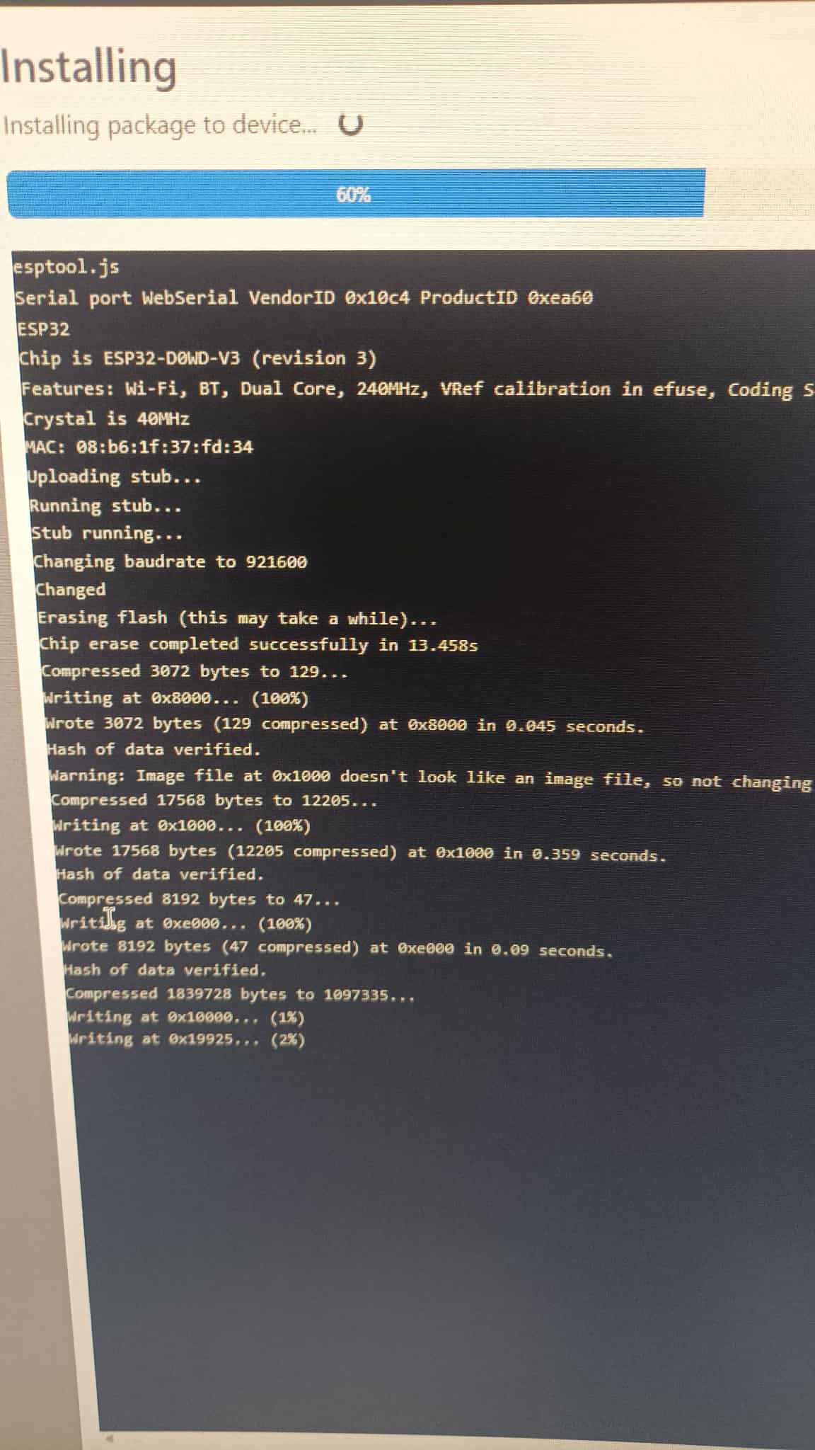
Felt like my nan trying to use Facebook throughout the whole install but got there in the end, at least I think! We’ll find out when the actual CNC is linked up to it:
I’m probably stupid here, but I’m stuck on the first step into the build.
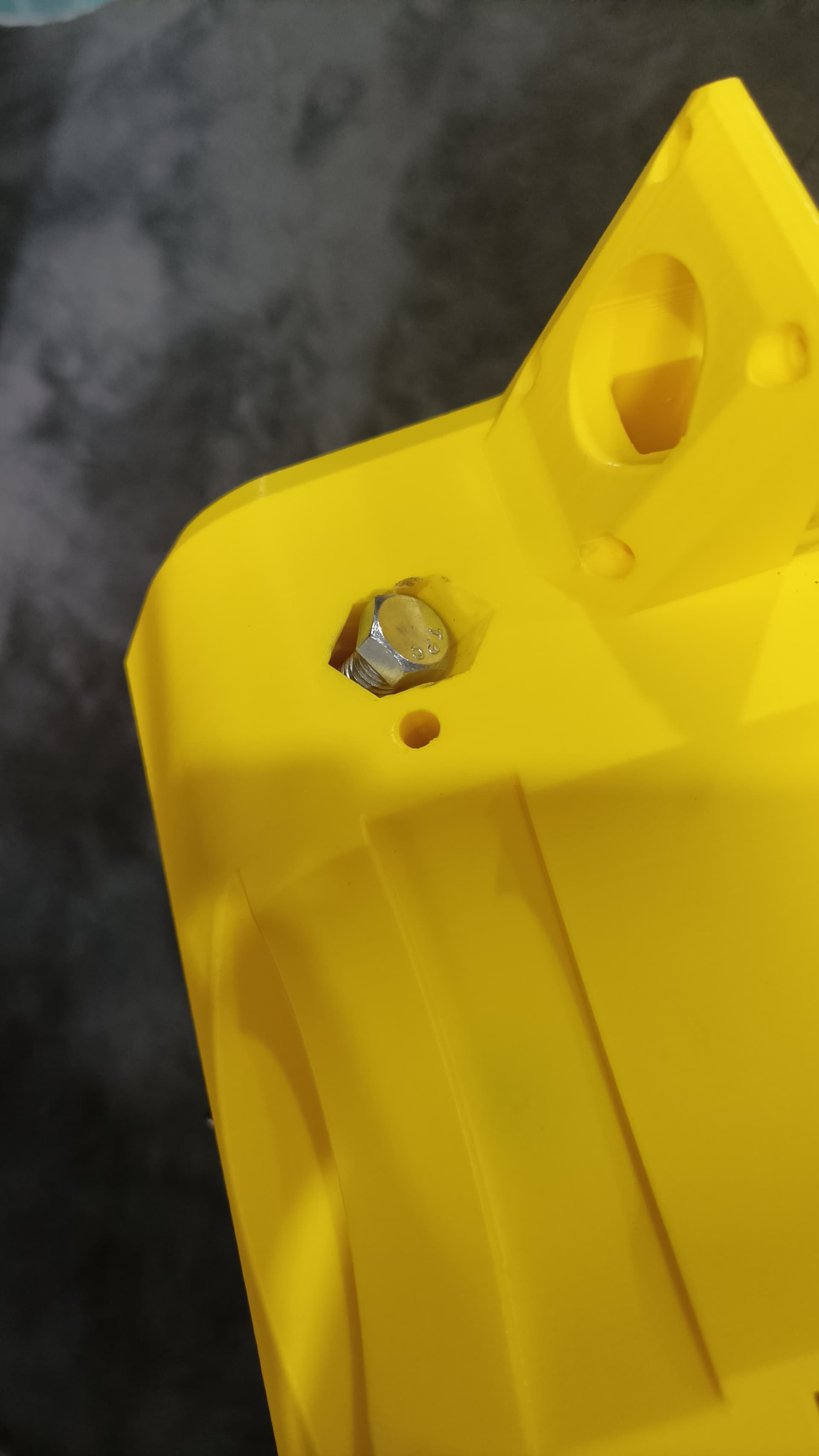
Following the directions in the docs, some bolts can’t screw in because there’s no space for the socket wrench head/tool
Doing them all the other way is fine, almost like it was designed to go the other way, with a large round space on the other side that fits a socket wrench head. I initially did it that way as it seemed the obvious way, then checked the docs and realised I was doing it backwards.
The ‘correct’ way though, I can’t screw any bolts in because there’s no space. This is the case for two pairs (4 bolts). (one pair is the tensioning pair which I realise shouldn’t screw all the way, but just for reference, that pair and the pair in the photo are ‘backwards’ to me, with the bolt head unable to screw further than shown due to no space)
Also, the other two pairs in which the bolt heads are just on flat edges, the nuts on the other side are in cavities/spaces that look the same as the cavities that the bolt heads are supposed to go in like shown in the picture, even more confusing.
Ok, quick update. Done for today, managed to follow along without too many issues.
My M5 button head screws have a button head that’s too wide it seems, for the idler (and likely other places?), so leaving it there for the night and will go buy ones that fit tomorrow.
Ok, so new bolts, all good. Getting more done, but hit a bit of a snag.
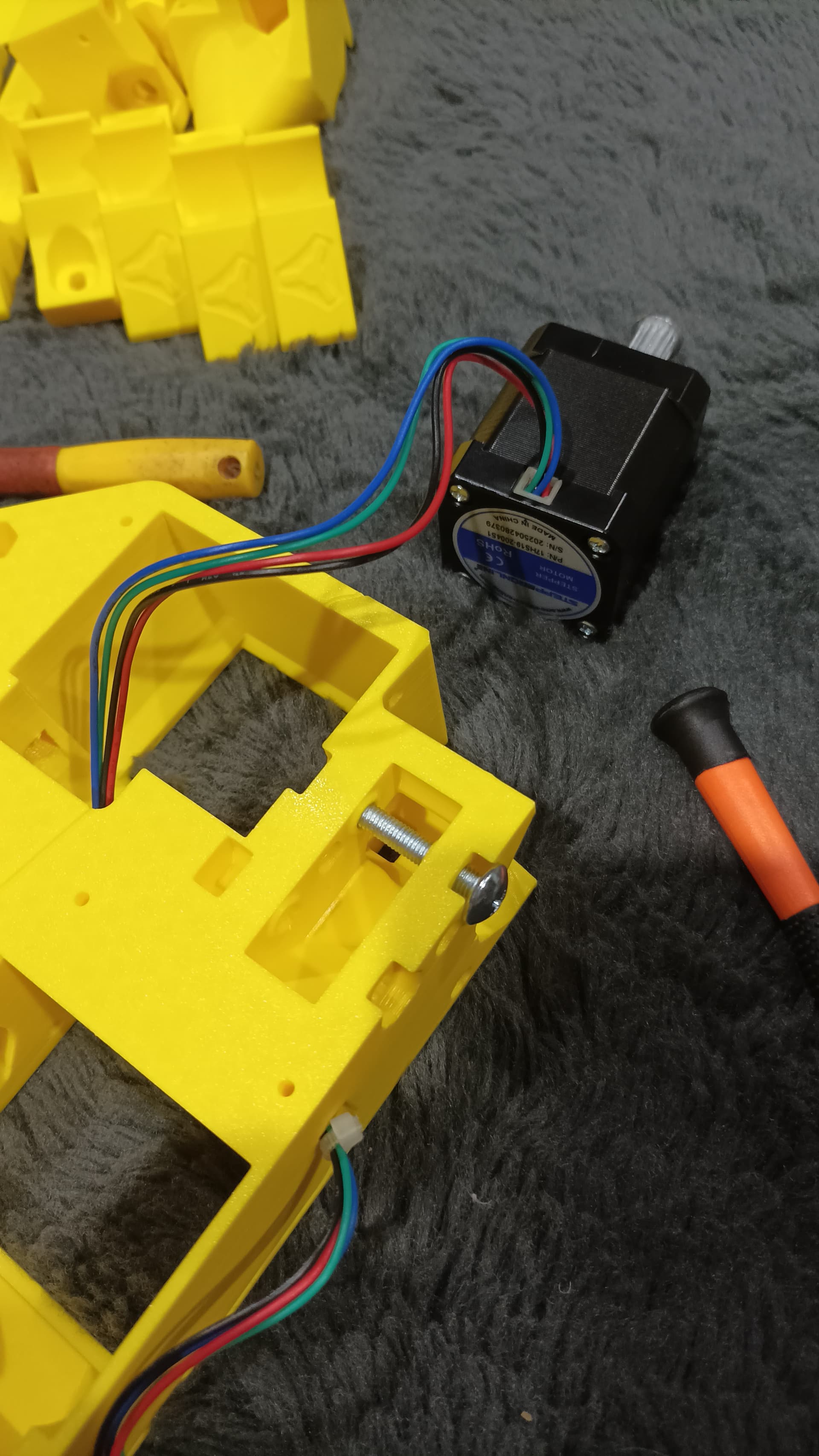
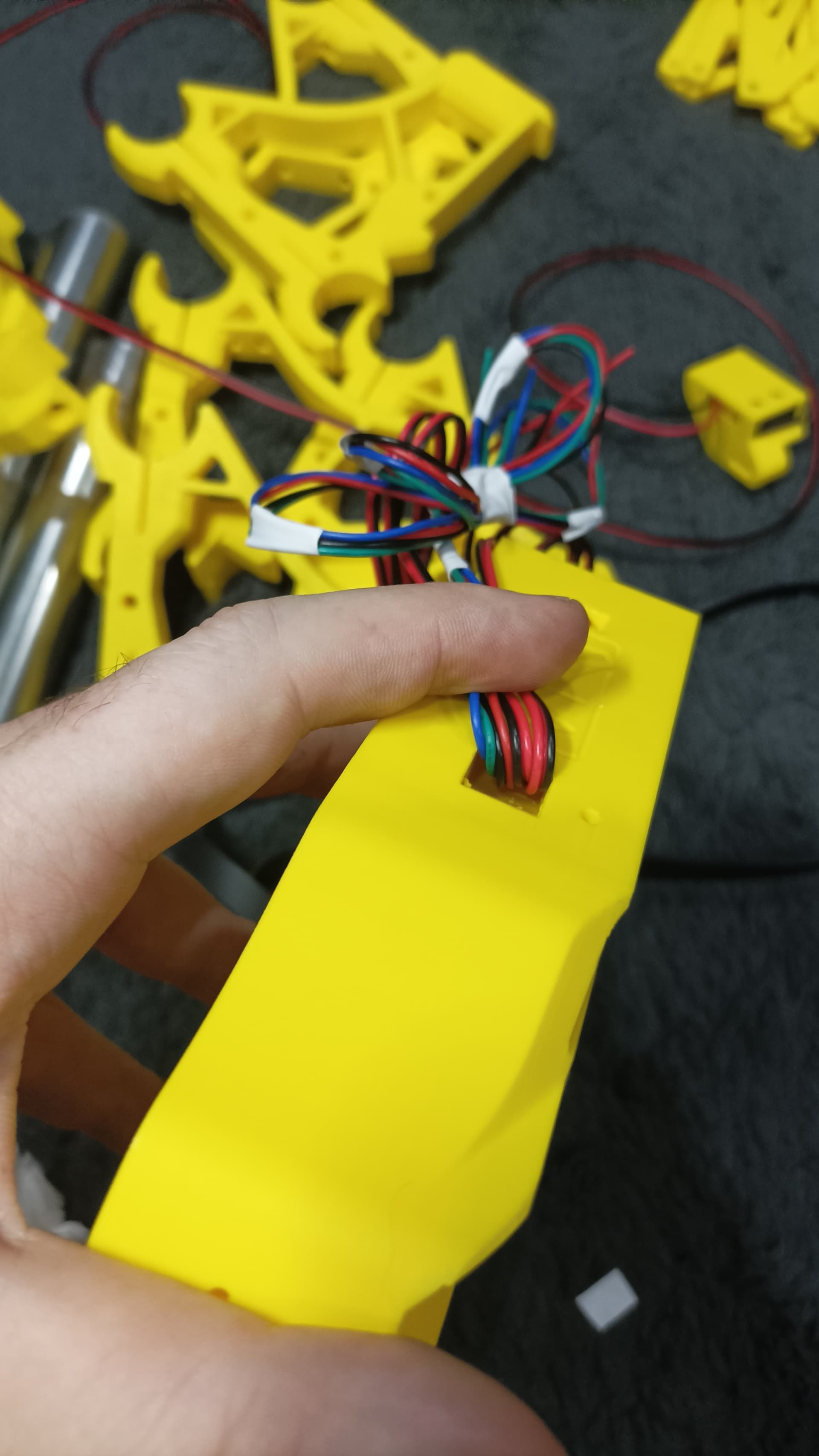
Whatever I try, I can’t get the wires for the coupler motor to come out the back of the XY. No idea if theres support plastic blocking it or it’s just too full of other wires (I struggled to get the last wires of the others through from the bottom) - one of the four will get through, but it feels like there’s not a chance of the other three of the stepper motor ever getting there.
I’ve tried for like an hour, I’ve tried sticking a second wire to the first and pulling it through, no luck, it’s just not happening.
As brilliant as the overall design is, I feel like a bit more space there would be much better, unless there’s some printing or build constraints that necessitate such a small space for all the wires to fit.
I’m trying to understand where they come through - from a tunnel under the other wires/tunnel? In which case I thought holding the other wires out of the way like this while threading through would help, but still no luck.
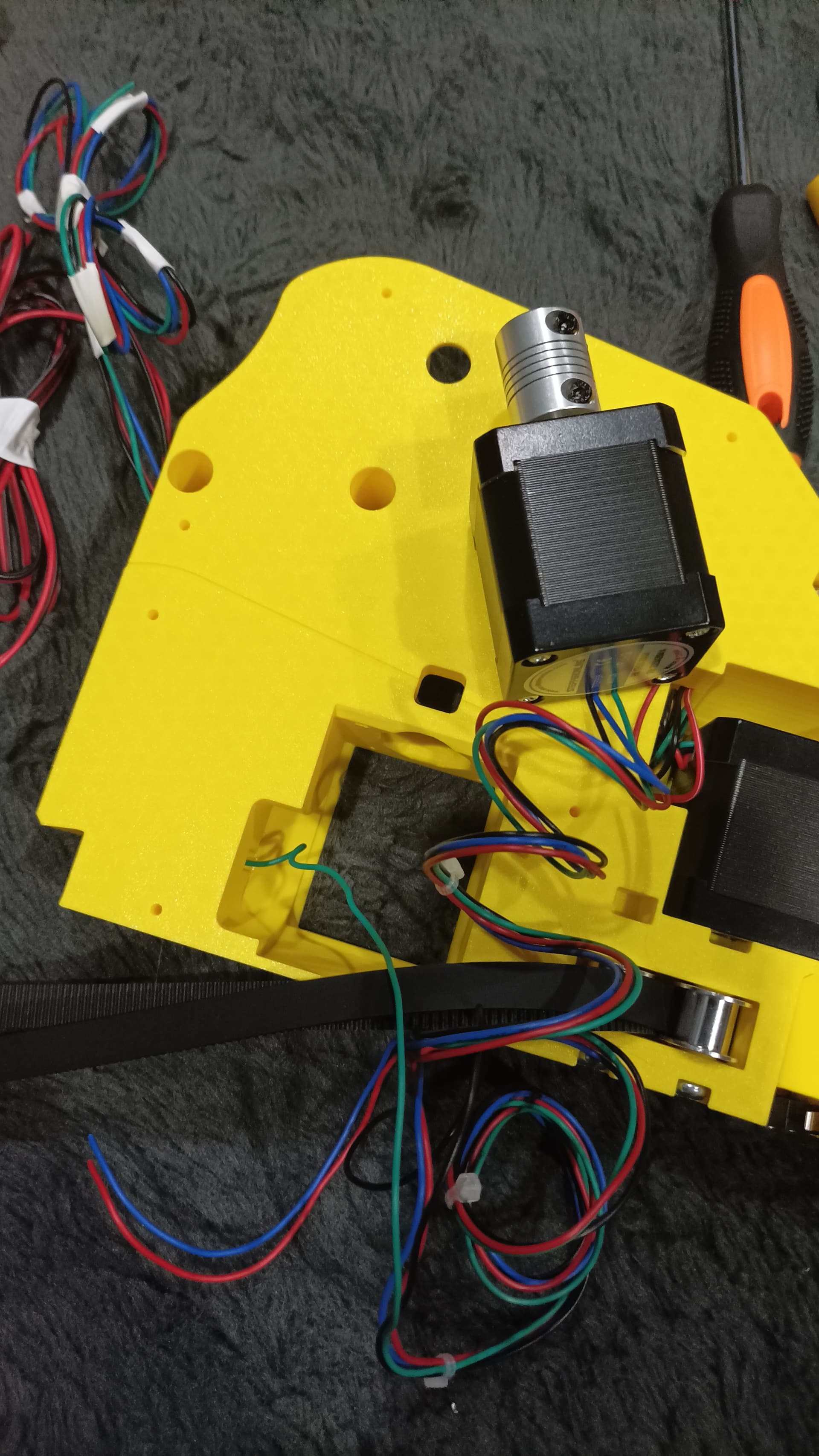
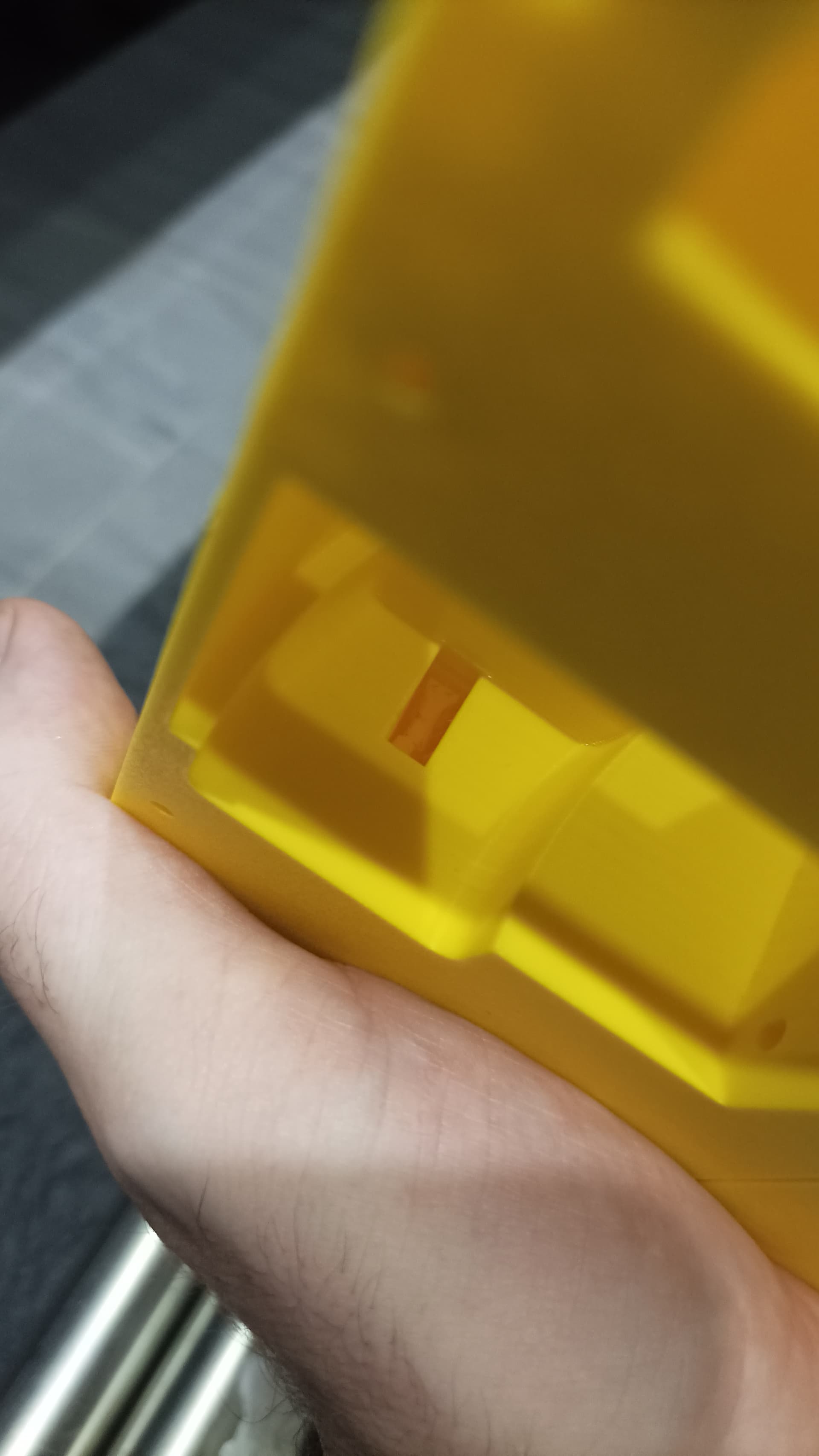
It should work pretty easily. You can just pull out the first set of wires a bit and then push both through together. I recall that yours was printed with supports though, so maybe there is some residue inside.
I just checked the other one and there’s support visible, very obviously blocked. I reckon there’s a little bit of support in the tunnel of this one that I can’t see that is stopping the last few wires from fitting.
New prints needed I think.
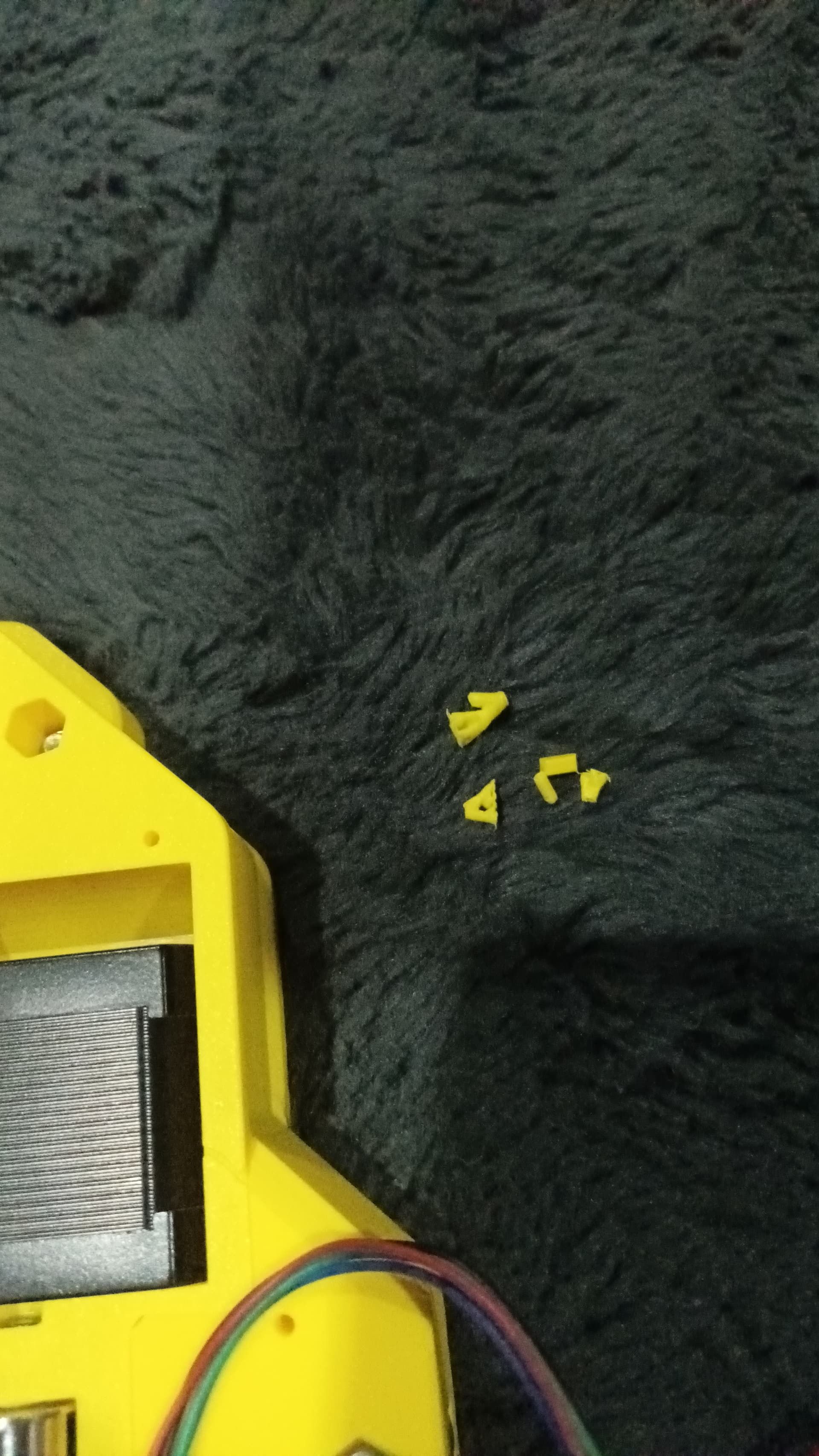
I might as well try clearing it as best I can first I suppose, I’ll have to take everything out anyway, so will remove everything I’ve installed then ram some stuff down the tunnel if I can and see if anything dislodges.
Well I managed it, you’re right, when not blocked it was easy.
I’m impressed I managed all but three wires tbh - this is what was inside the tunnel and not visible. All good for one piece, will try and get the other one cleared out now.