Yeah, it’s pretty incredible engineering. 
Small update today - moving the build to it’s forever home in the garden outhouse. Had to buy some boards to create a table top over my previously built metal frame.
Discovered recently that MDF is a no-no in a humid country like Thailand, warping and mould within days, so after a bit of research I realised humid countries use something called HMR (High Moisture Resistance), which I think is a treated form of MDF.
It’s widely used for cabinets and in bathrooms, kitchens etc and is a lovely green color.
About 25% more expensive than MDF.
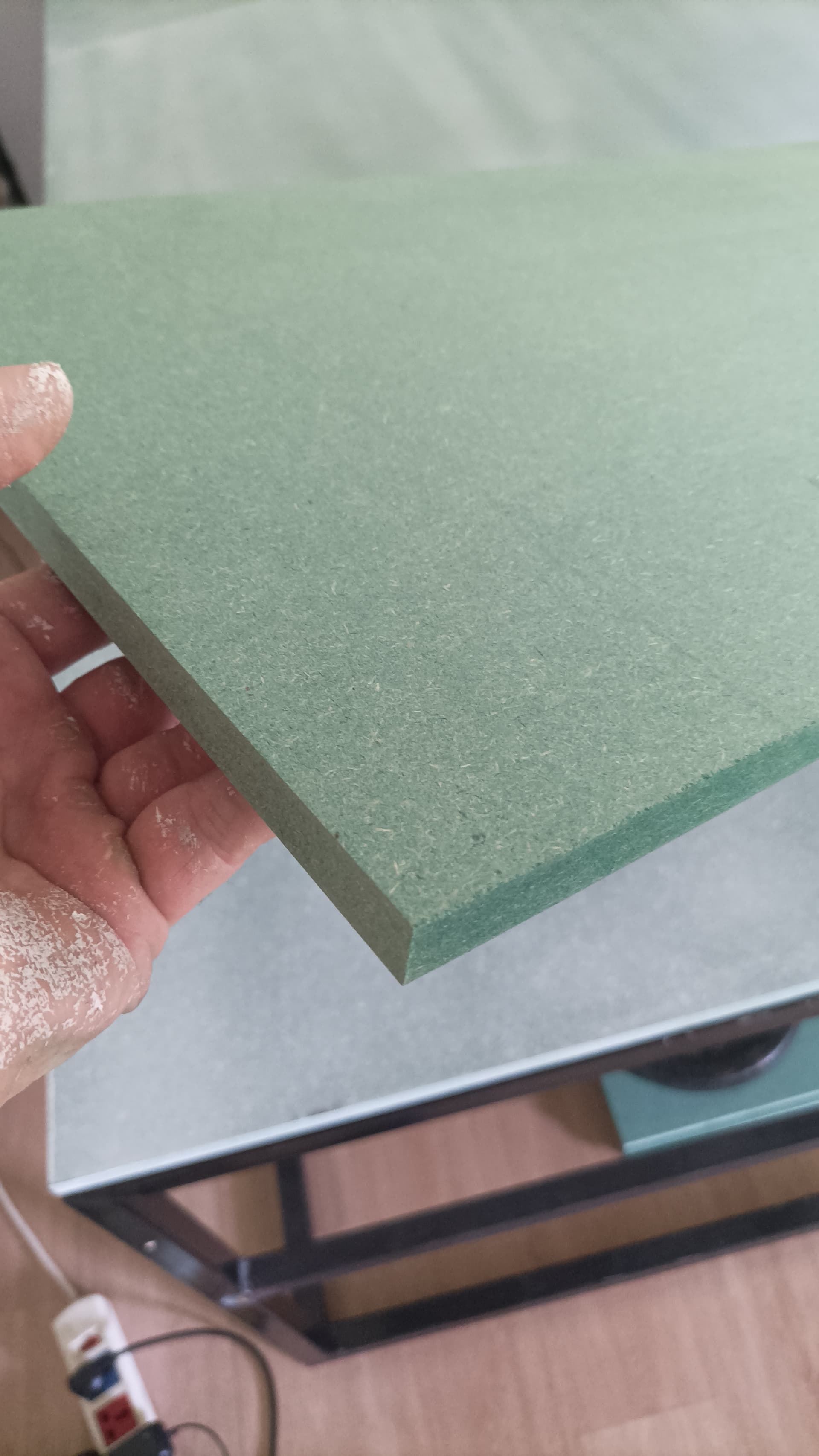
I used three boards over the frame, gave them a light primer coat and brushed the edges with primer just as an extra precaution and because I had a little to hand. Thought maybe primer helps seal a little? How much it will help I don’t know, but can’t hurt I figure.

Plan is to use No More Nails or something to that effect to glue to the frame, but for now just adding some weights on top to keep everything flat til the time comes.
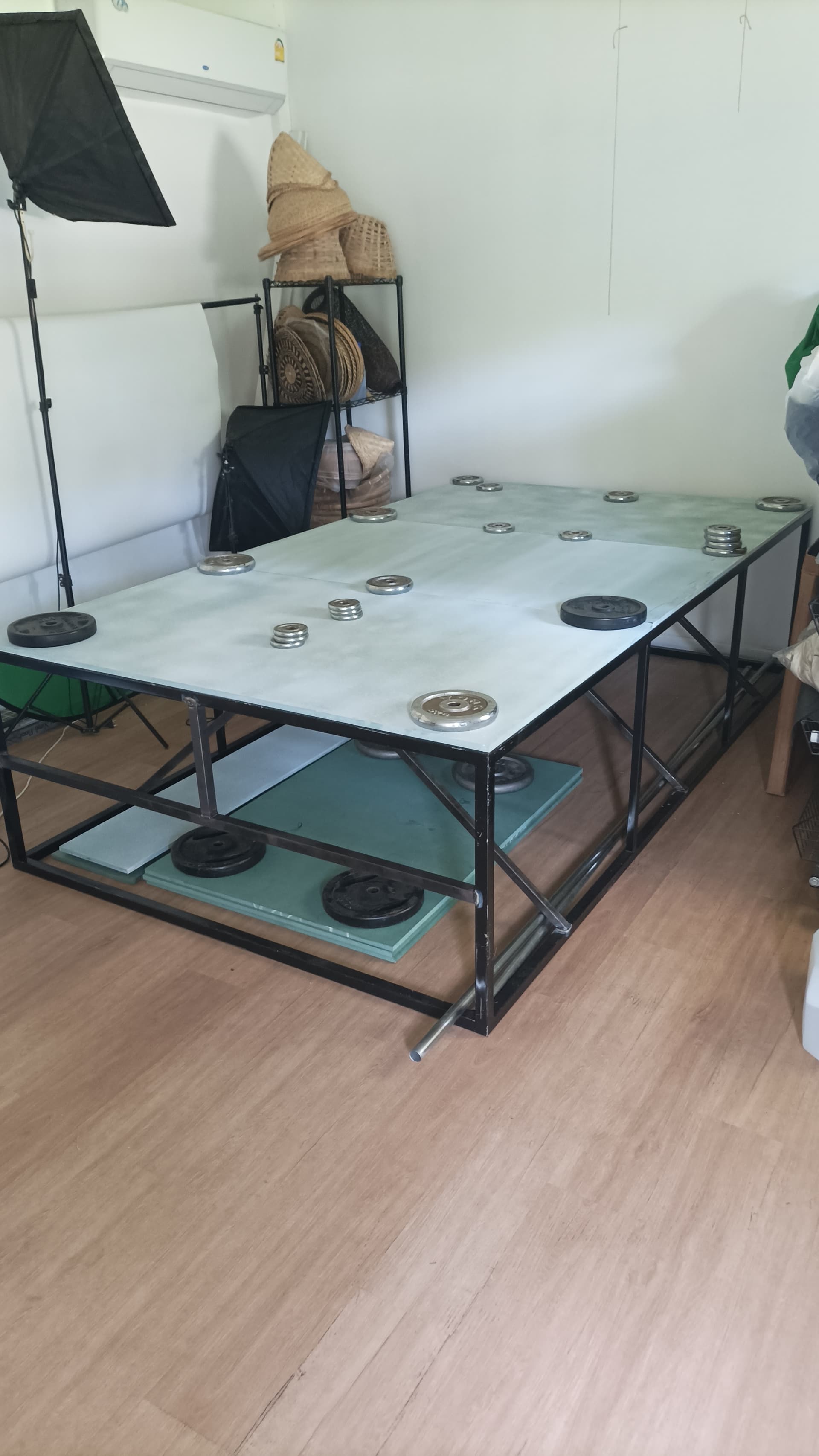
Eventually there’ll be a HMR spoilboard/full sheet on there.
I’m wondering about HMR as a CNC material also, will be interesting to see how it compares to MDF.
Also wondering if it makes sense to raise the parts the CNC rails will be on, essentially adding another layer of board under them to have it the same level as the spoilboard? Is that the standard thing to do?
Have a question - here in the docs it says to screw the Z nut onto the lead screw brass face down. It doesn’t mention it again from what I can see.
Is the Z nut supposed to connect to this other bit (in my hand) that screws into the plate at the top in the next step, or does it just sit on the lead screw on its own?

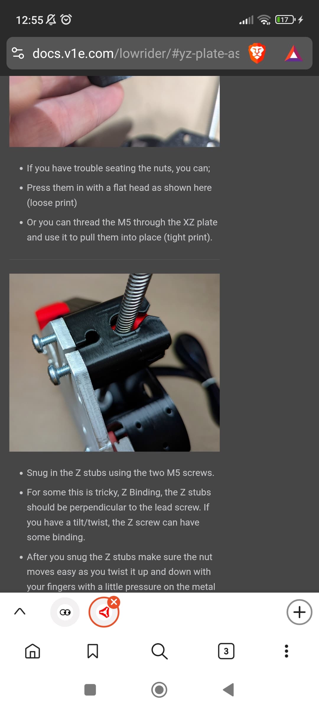
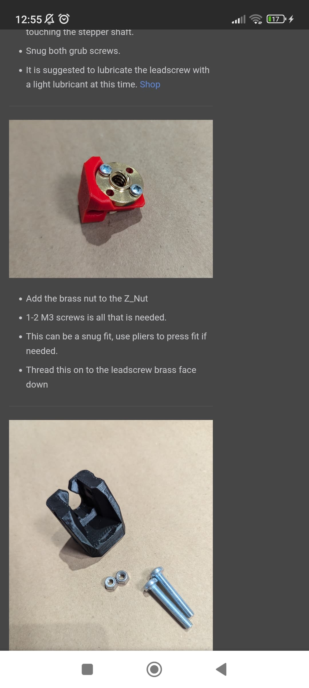
I’m assuming they fit together, and a bolt goes through this place:
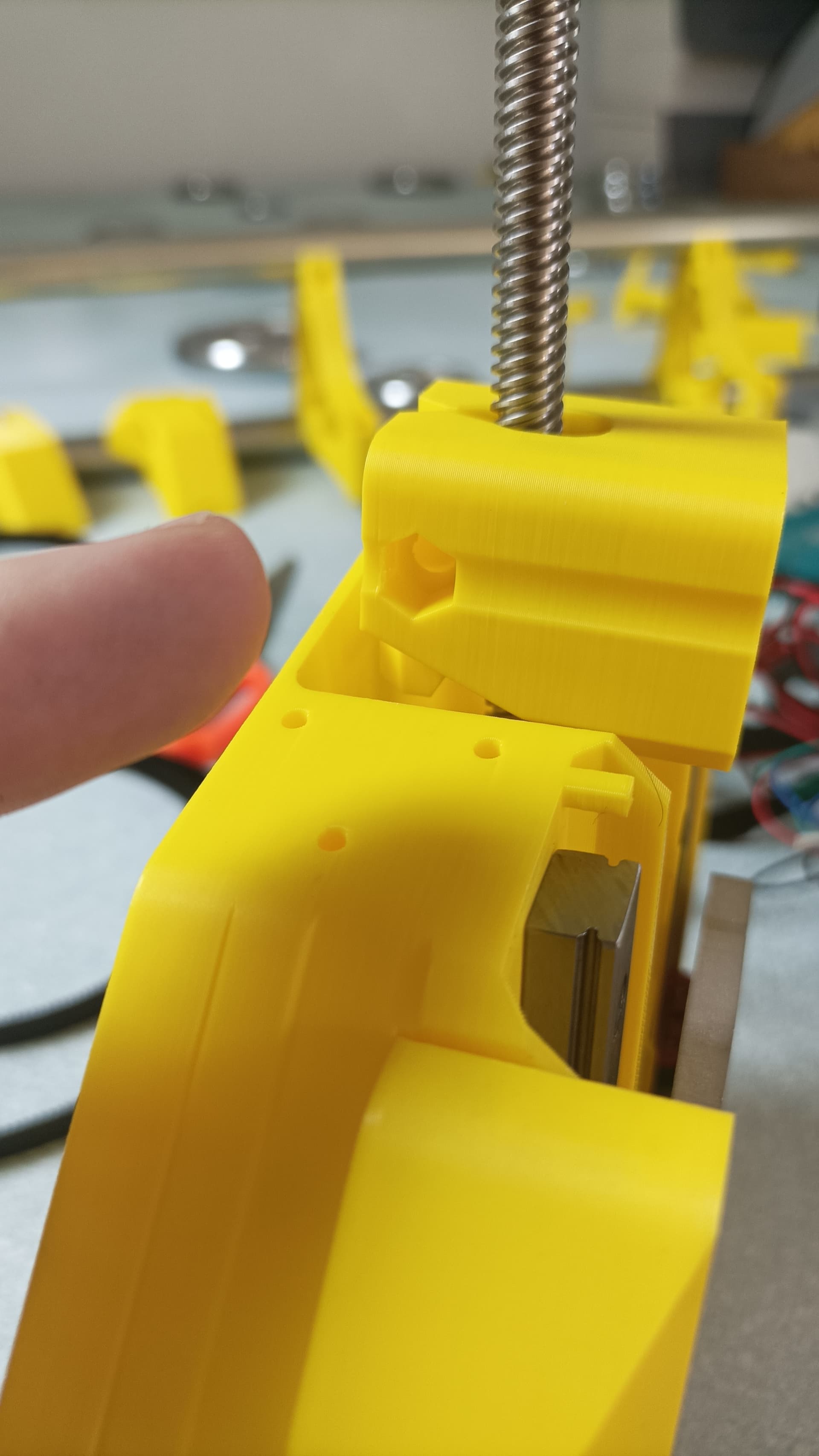
It’s just not done/shown in the docs so I’m unsure and want to confirm it’s not something I should leave at do at some other point?
Impatience got the better of me and I did it anyway, living dangerously.
Got the core and sides done, so far so good.
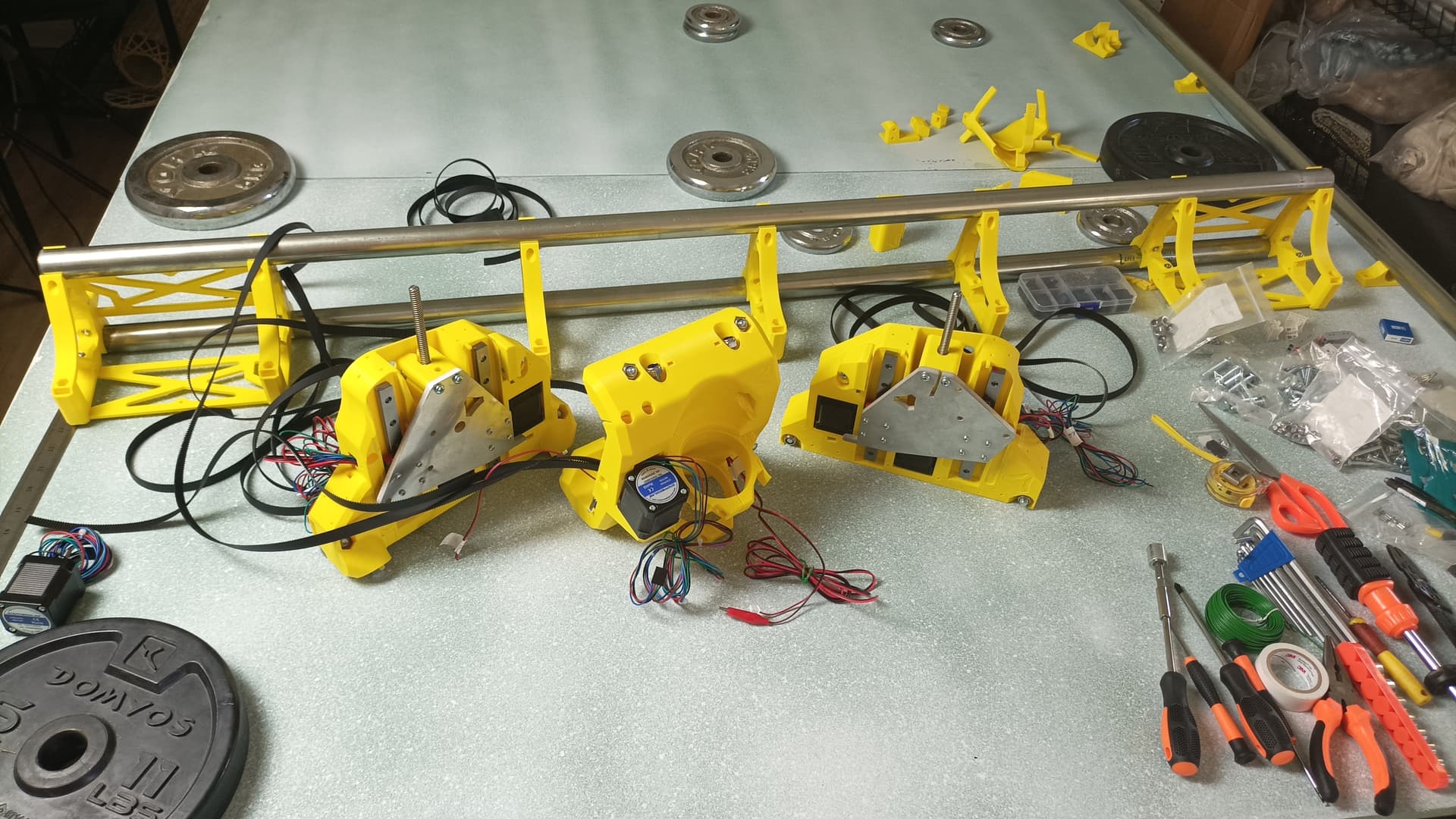
Been a few hiccups but nothing that’s made me want to quit as of yet.
I’m definitely on the complete noob end of builders, no knowledge of CNC or 3d printing stuff in general so there’s been a few parts in the docs that have been confusing, a few small areas or descriptions that could be made more clear/noob friendly if that’s something worth doing, but I’ve got this far so they’re definitely good enough for even complete newbies to follow and work out eventually.
Easily my least fave part so far has been discovering the rails have little ball bearings inside.
I didn’t realise one edge stop plastic thingy was snapped/missing on my print:

.. so after affixing the rail, naturally I gave it a good slide back and forth and it went off the end a bit and ball bearings fell out. Not fun. Googled a bunch to learn about linear rails and spent ages figuring out how to put back.
Aside from that though, can’t complain, it’s getting there!
I’d remove the screws from the stub and nut holder again or just put them in very lightly. They aren’t needed and are a remnant of the design process and can cause binding when hindering the nut holder. 
Ah, okay, thanks!
Ok, without the bolt it would separate and then get stuck, meaning no travel one direction. I added it back but just left it light just in case.
Sides and core are on - measured heel toe and both pretty much the same
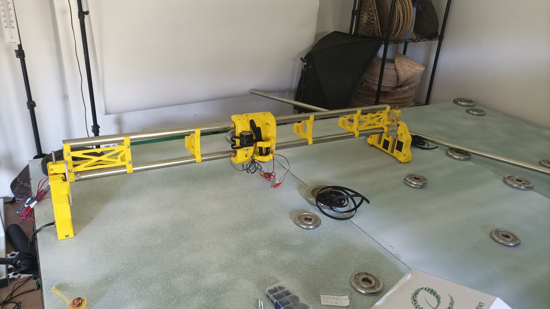
One thing I noticed though just while moving it in general (for example, picking it up and rotating it for better access position then placing it back down) is that the wheeled side will move a little, which of course ‘bends’ from the other end/side. I discovered that the screws in the linear rail of the non-wheeled side come loose - when the wheeled side moves forward/back a little, it pulls the linear rail off the plastic on the other side a tiny bit to account for the movement.
I tightened all the screws, but they just loosen again - I remember reading about using loctite, any issues using it for those linear screws?
Separate to that issue, I also noticed movement tightens up near the bottom of the Z range when turning the Z screws with my fingers - is this expected?
Nope.
Originally, this was intended, but it really just causes binding for people. Leaving that bolt out entirely is better overall for the machine operation.
In theory, the slot in the nut holder should have allowed enough motion, but the restriction that it does place on movement is enough to cause binding, and the whole thing is better off without it.
On the subject of binding…
Screwing the brass leadscrew nut into the nut holder, do not screw it in too tightly. The nut needs to be free to adjust slightly to the real world position of the leadscrew. The leadscrew will have a subtle bend to it, they’re never truly straight, and the couplers connecting them to the motor shafts are never perfect either. The nut needs to be able to wiggle a little in order to adapt to the real-world alignment of the lead screw. not much, but a little. Think of the screws that hold it in place in the nut holder as preventing it from rotating, rather than holding it in. Gravity does the real job of holding this all together, as well as making the tool plunge into the material. The LowRider is not designed to apply compressive force underneath the gantry (much) greater than its own weight.
Loctite probably isn’t going to help with the screws into plastic. If it’s excessive, then a bit of glue may help. Once the belts are in place, there ought not to be too much morement between the 2 sides.
Thanks, I’ll try loosening the brass nut screws a little, and will try again completely removing the bolt through the two parts.
When I removed it, I would turn the Z screws with my fingers and go down, then the znut piece would separate fully from the outer piece at some point. Then when turning the Z screws and trying to travel back up, the Znut would get stuck under the outer piece due to its rotation when separate making it not fit inside the outer piece again. (Like trying to put a square in a square hole - except the square is twisted like a diamond so won’t fit)
I’ll have a good look today and see if I can figure it out, I’m sure I’ve overtightened or done something wrong somewhere leading to binding / tightness and this issue.
Is the tightness at the bottom of the Z travel range normal or should it be the same throughout the whole range and simply stop at bottom/top at a noticeable point?
I think what happens is the aluminium plate/rails don’t fall by gravity alone on one side. I noticed this when doing both sides, one set of rails moved faster than the other, one would kinda get ‘stuck’ a little and need a bit of a push
So for example, this is the start posiiton:
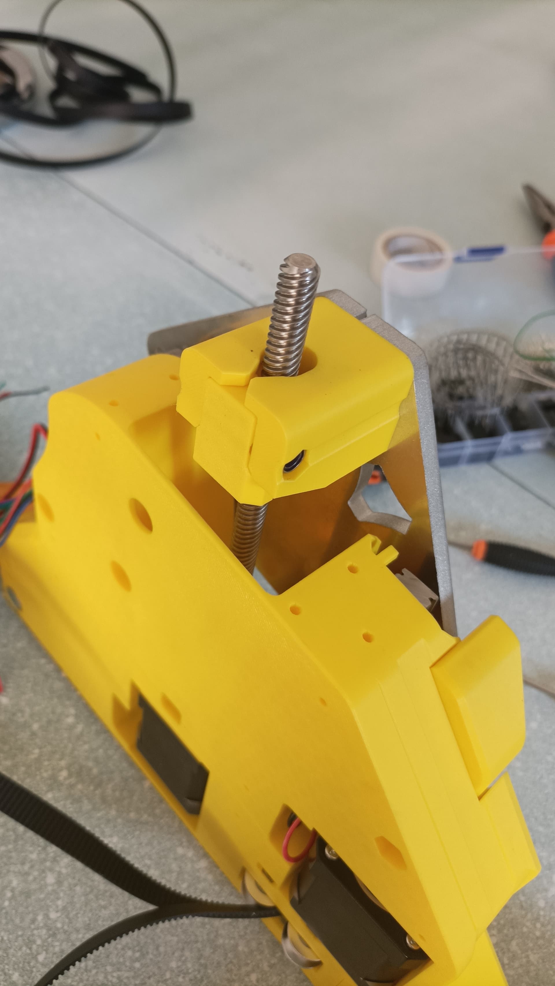
I then turn the z screw to go down. Because the plate/rails are ‘stuck’ and need a bit more force to move than gravity, only the Znut goes down as I turn the screw.
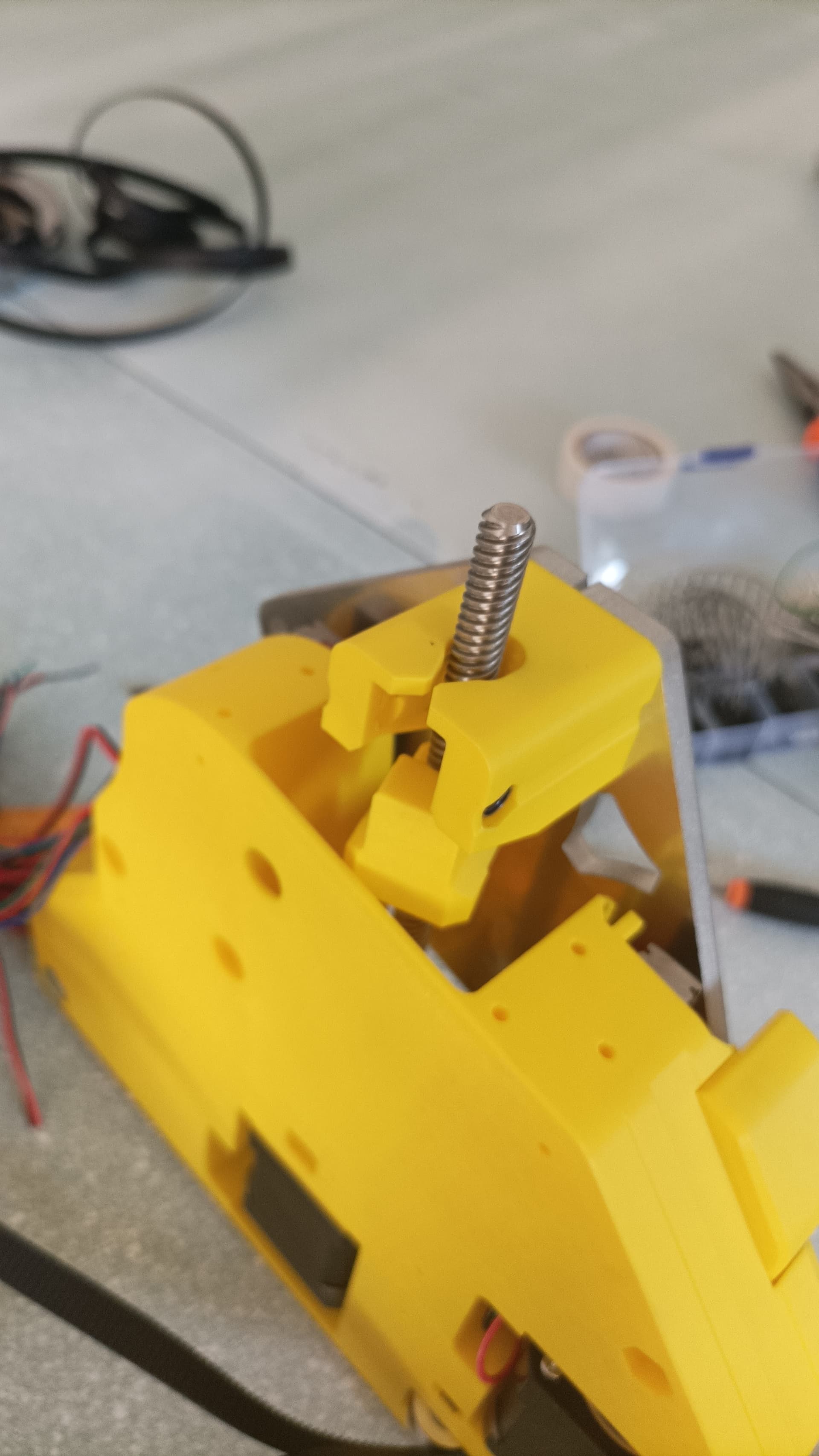
Once separate like that, the Znut will not be aligned with the hole for it in the stub/outer on the way back up, and will just get stuck.
So from what I can tell, the issue is caused by one plate side not moving too freely and gravity not being enough to drop it down. If I give it just a slight push it will drop a bit, it’s not fully stuck, it just gets ‘stuck’ sometimes if only gravity is used, too much friction somewhere maybe.
Any idea why this could be?
When the bolt is through the Znut/Znut holder stub pieces it’s fine of course, the Znut being linked is enough to pull the plate up and down, so it’s a necessity on this side at least unless I can figure out the ‘sticky’ plate/rails issue.
– Testing more, even with the bolt through the znut, which does pull down the plate down with it, it’s going to cause problems because there’s a 1mm gap or something between where the plate is ‘stuck’ and only the znut moves and where the znut bolt engages with the stub outer and the plate gets pulled down with it, which will cause issues for sure.
So the big problem here is one rails/plate side not moving freely enough I think.
I’ve seen that happen a few times. 99.9% of the time once you have the weight of the beam on the plates its non issue. BUT usually when I have a set like that I lube up the bearing blocks with some Super Lube Oil and that smooths them right out.
Thanks, I think I may have figured it out - whether this will cause more issues though I don’t know 
I removed the plate and everything to check the rails on their own and the blocks were still sliding a little friction-y unless I put pressure on them and pushed them tight to the rails.
I loosened the linear rail screws just a little, like 2 turns, to give the rail just a little tiny of leeway and wiggle if I moved them with my hands as they were really in there really really tight. After that, lovely movement of the rail block.
So in typical fashion I had an issue caused by screws too tight on one side, and too loose on the other, thankfully I didn’t end up putting loctite on them!
So I’ve put it back together, it seems ok, will do more measurements checks again but I think there’s an improvement. There might still be a little friction, but I think when the router is on the X rail along with everything else, that extra weight will surely be enough to counter any friction and have the sides dropping like normal.
I needed a few more parts printed (dust shoe and other cable management stuff) and lo and behold, there was a Black Friday sale on 3d printers. Convinced the wife to let me have an early xmas present and now have an A1 on the way. A little late for printing the main LR body but I’m sure it will come in handy as I complete the build further.
The main convincer though was showing her I can print hot wheels tracks and related toys for our son, that’s pretty cool.
Is my touchplate wire coming out of the wrong end here? It comes out of the back of the core where the end stop sits. Something seems amiss now that I’m trying to wire it all up and sort how this wire management to the jackpot works. (It’s not the ‘front’ bit with the clip & plate, it’s the wire that goes to the jackpot board, it’s just short here as I haven’t extended it yet)
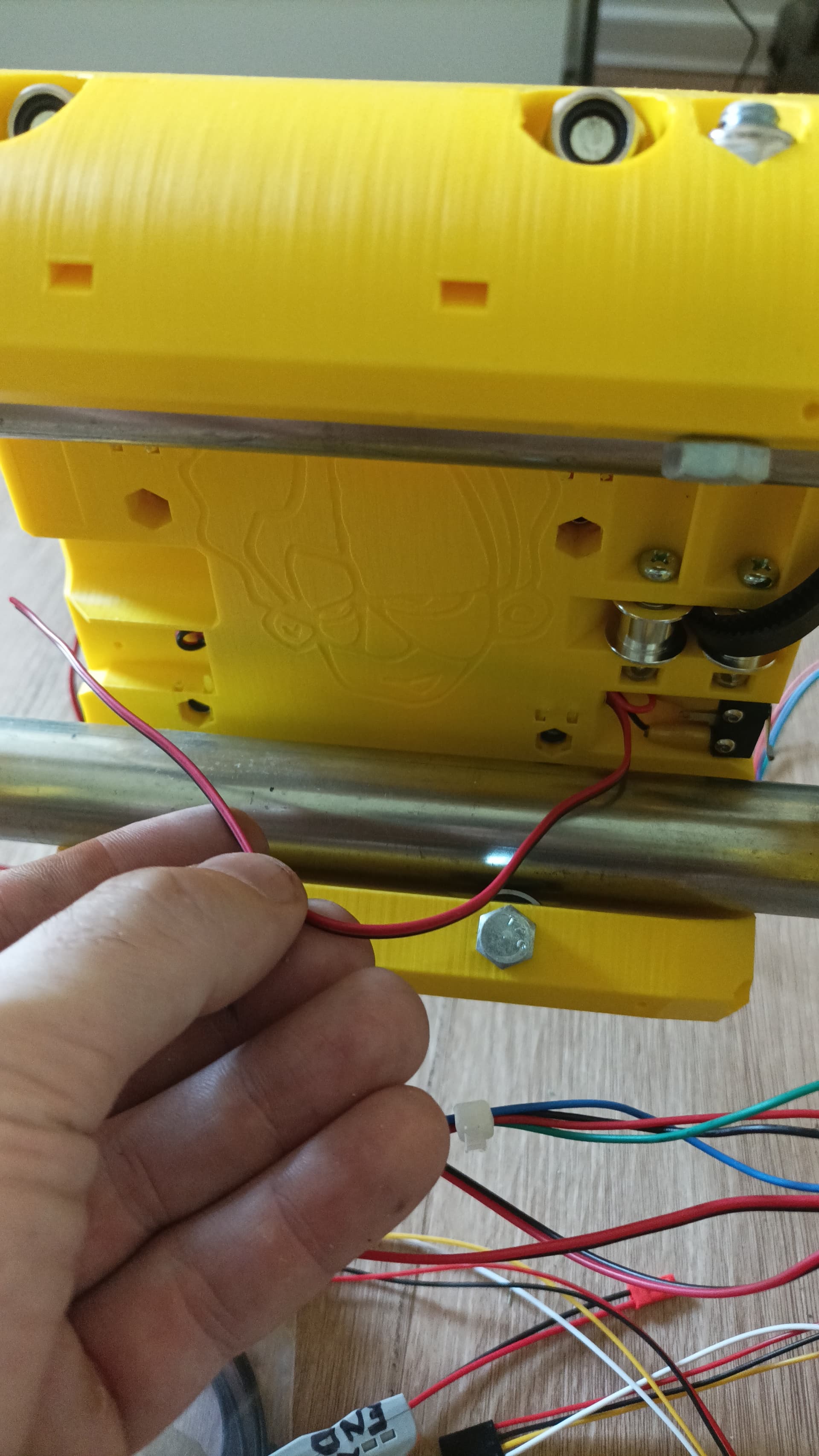
I’ve missed something here in the docs. It says go through the hole then through the tunnel, left to right in the pic, which I’ve done. Then when you get to the next step and pic about end stop wiring, the touchplate wire has been put back through somewhere? Where is that? Surely not back through the tunnel it came through, that seems a bit redundant?
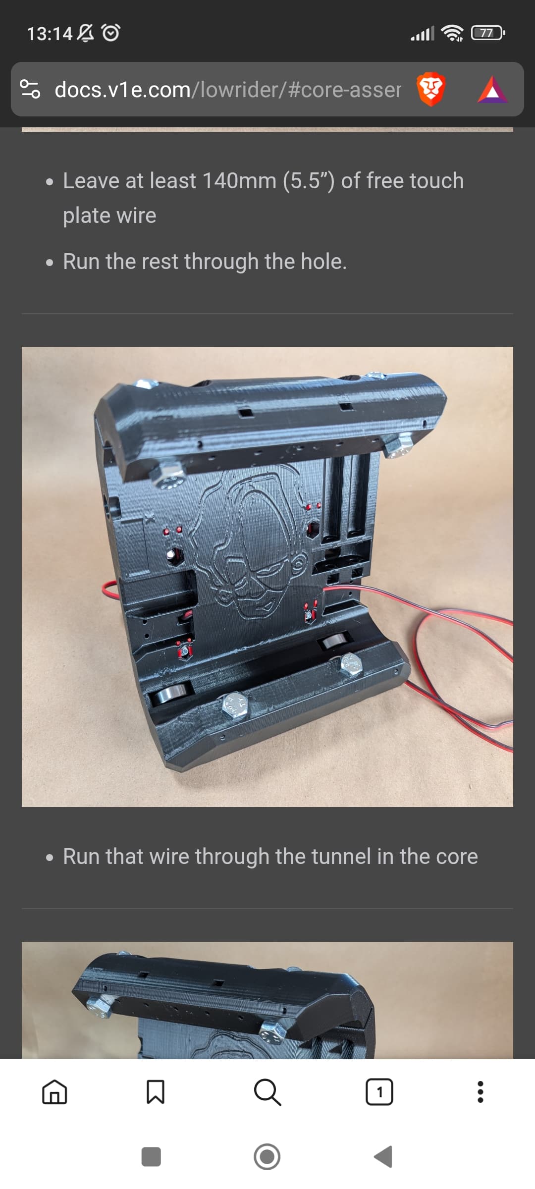
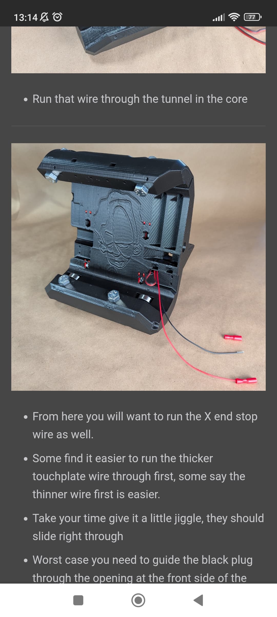
Edit - oh, I see what I’ve done wrong.
So after the tunnel step, it wasn’t clear they had to then go out through the front and come out where the stepper sits And after the step ‘Run that wire through the tunnel in the core’ the next step is worded confusingly, saying ‘from here you will want to run the X end stop wire as well’. I thought that meant run the X end stop wire from here through the tunnel as well, and thus out the front on the other side.
The way that’s worded.. come on.. You’re messing with me.
‘Run that wire through the tunnel in the core’
‘From here you will want to run the X end stop wire as well’
Run as well.. run.. as well.. run the X end stop wires through the tunnel in the core is the implication there surely! It can’t just be me.
So essentially my end stop wire comes out of the front where my touch plate wire enters.
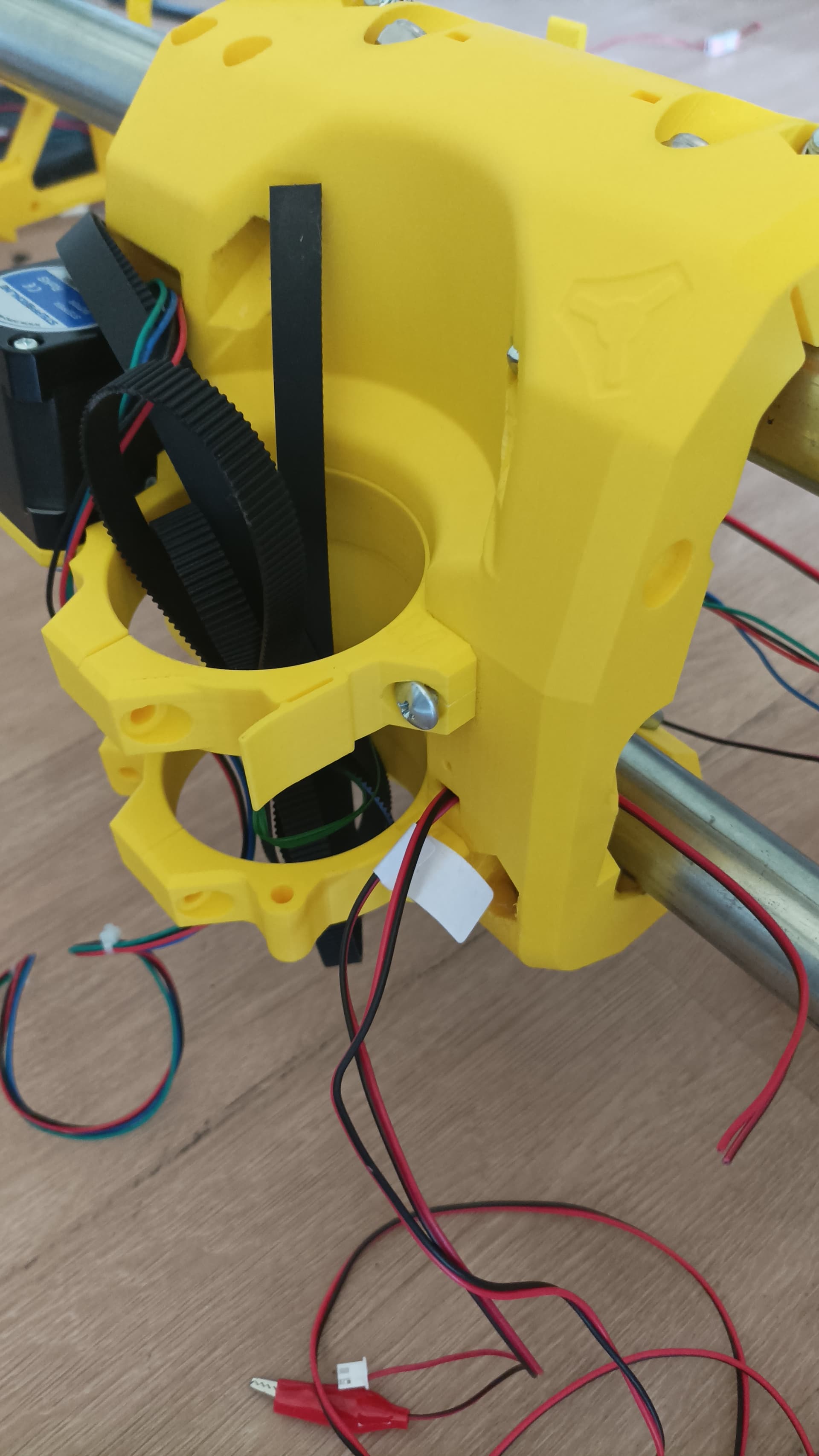
Not sure if I’m able to do anything without taking the core apart here to rewire?
I wonder if I can tape the touchplate wire to the back of the core and have it come out the side? Would that be an issue? I think so actually, it would hit the wire as the core reaches the end.
Argh what a pain. I think I’ll just leave the touchplate for now and look at it again in future when everything is hopefully up and running and I have a better idea of how it’s all moving. To be continued..
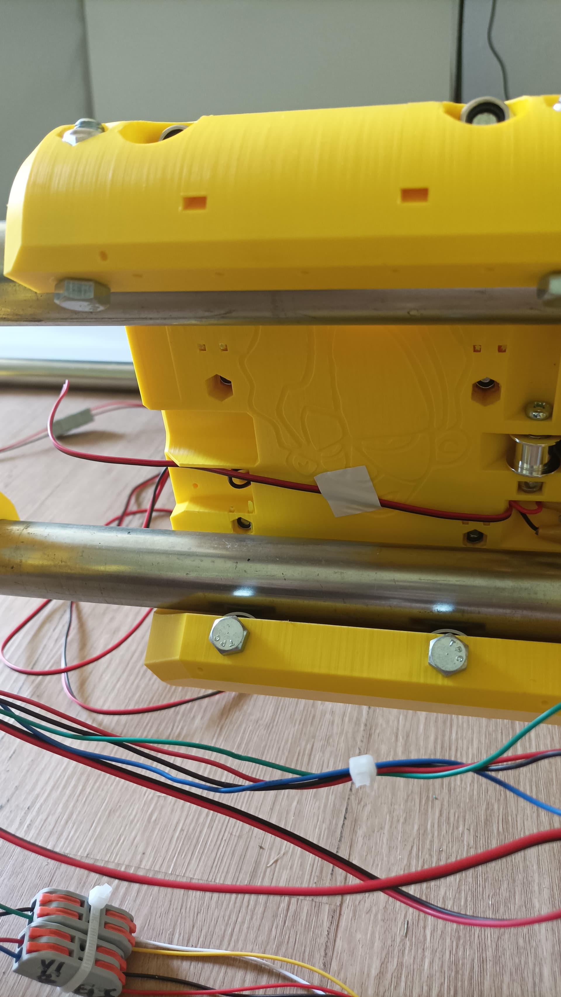
Do yourself a favour and take the core off again. You just have to jog the LR to the top and pull out the top rail a bit and then can slide off the core. Especially the endstops should be wired correctly.
Ah damn, if it’ll cause issues then I’ll have to grin and bear it. It’s on me for not matching photos and wording and asking here I suppose, lesson learned.
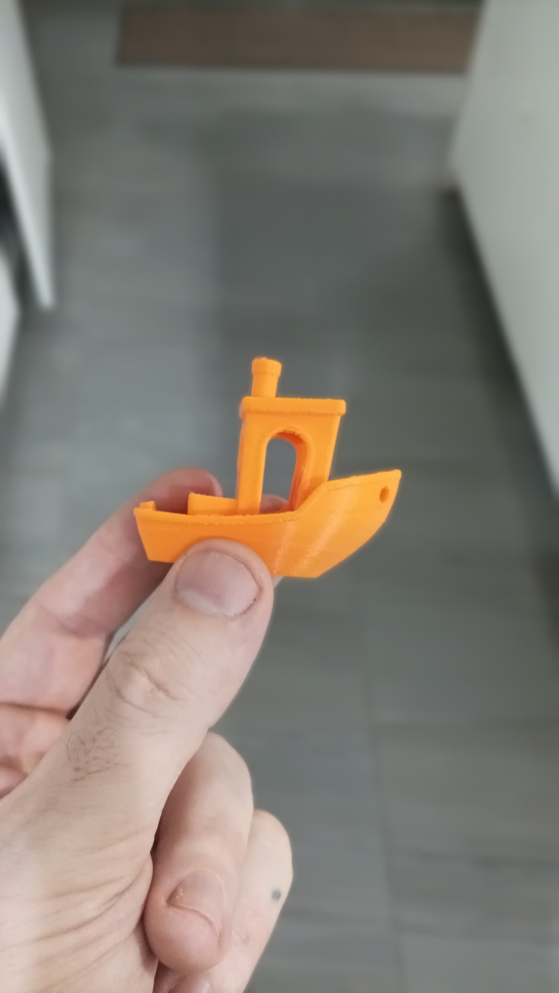
On a more positive note, first print today!
I’ve been geeking out for hours, the ease of printing random stuff from your phone is just so wild, before even touching on modelling your own stuff.
Is there some kind of trick to getting the belt through this part?
In the docs it goes through, wraps around an M3 screw and comes back out the same way but the slot on one side (where it’s coming through here) seems quite tight and I can’t quite get it to come back out. Nor will it stick in place wrapped around the screw snug into the hole, pulling the belt when it’s snug in there just makes it come loose after a bit of tension, I think it needs to come out the other side.
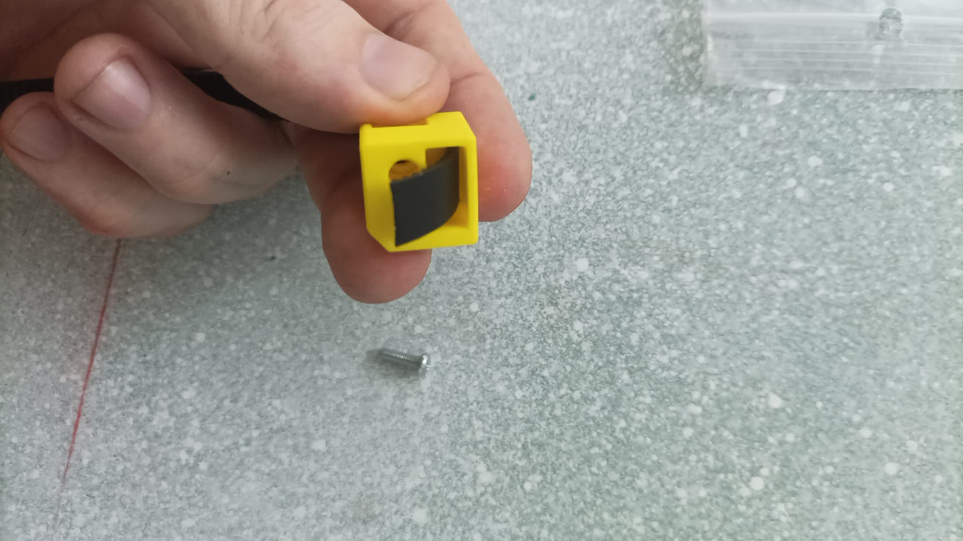
It is tight, but you can pull it through.
Is the M3 screw being pulled what helps it get through? Wrap it, line up the belt and the gap as best I can then pull?
I did it without the screw before. Cut the belt at an angle, as soon as you have the tip in the slot you should be able to pull it through by tugging on the belt.