Made it to RMRRF 2025 and was able to see the LR4 in person and that was the last straw to upgrading my LR3. It has been working fine for me but was only a 2’x4’ cutting space, well just under 4’ actually, will be an issue later unfortunately. It has been my goal to upgrade it to a full 4’x8’ sheet build so I can do cabinet cutouts. Seeing the LR4 and knowing that I was going to have to redo the main beam, rail and belt systems already I decided to just go all in and move up to the LR4, so the adventure begins.
As I don’t have a space to host a full sheet build just yet I am starting with the table to sit it on. I am going to do the ~$200 non-cnc table the Ryan put together here - LR4 easy Table
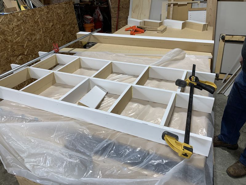
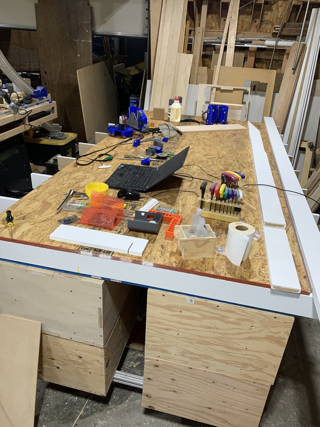
This table is a bit more than $200 with the current market where I am, but still not an issue. I had some OSB and MDF sheets in the stock, so that helped. At this point I have built the center of the table with the torsion grid.
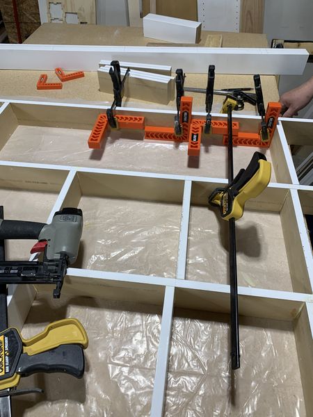
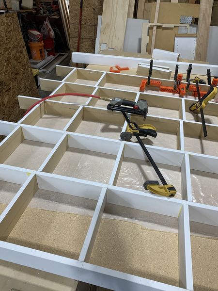
Maybe a bit of over kill, but we were using some corner clamping braces to make sure that the center braces between each to the main ribs was straight up and down. Just glue and brad nails at this point so far. We ended the day with the full torsion box built and the bottom layer of OSB glued and brad nailed in as well.
What it is sitting on in that last photo is going to be the base of the table. I have been using the LR3 to cut some cabinets and they are setup on a metal frame with wheels. I have 4 more cabinets to get done to fill the last spaces on either side of the table. With those done I will be able to have support on the main ‘bessel’ points of the table. I should be able to move it around my shop as well if needed, hopefully. Might have put too small of weight capacity wheels on it, but will see how it works out.
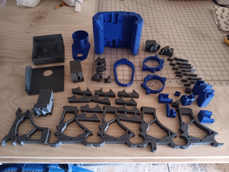
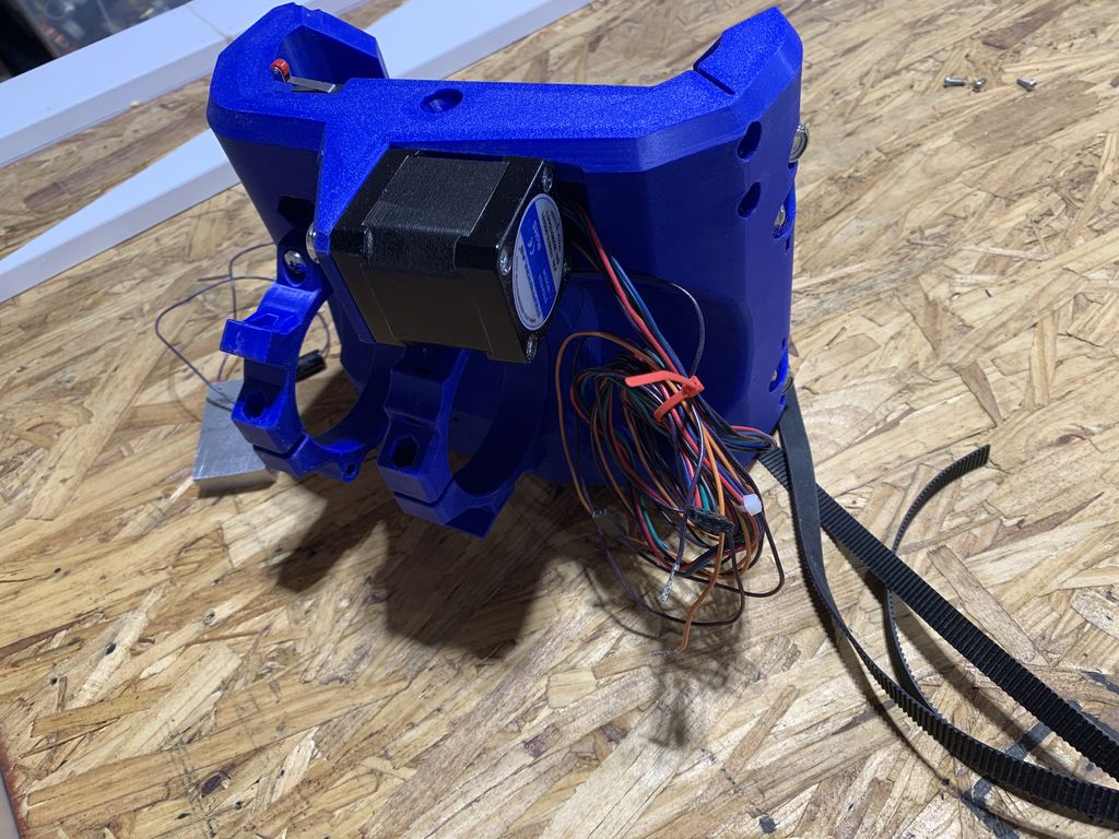
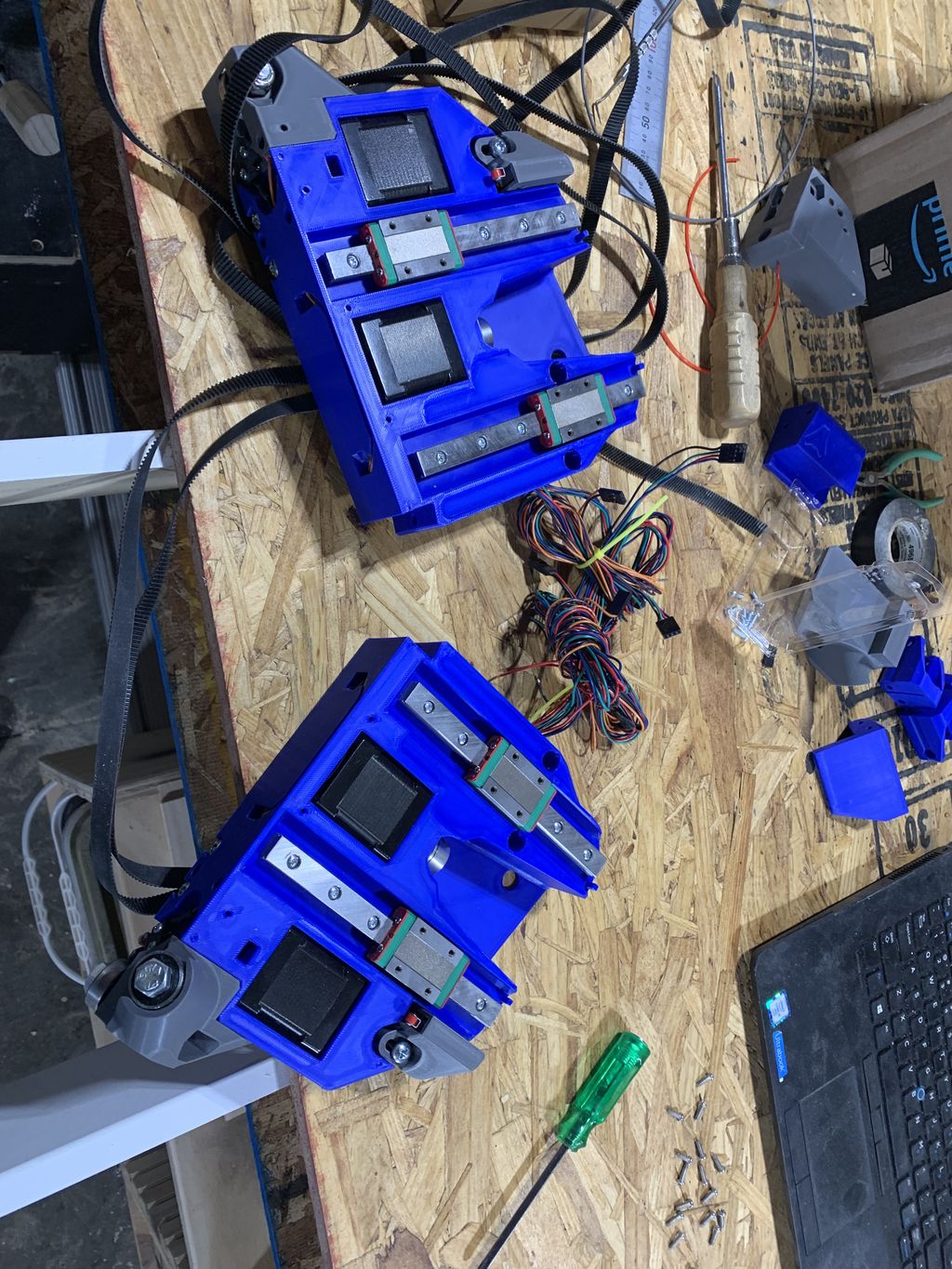
Was hoping to start the built at this point, parts are almost all printed.
The keen eye will notice some missing YZ min and max plates and beam braces. Had some issues with a filament order and wrong colors. So correcting that and will come back at that later. But this is a good start I think.
In parallel to the table setup and waiting for parts to print I have also been working on the XZ plates and the struts that are needed for the beam. I was hoping to use my LR3 for both of these items, sadly that wasn’t possible.
For the two strut plates on my beam they needed to be 1389mm in length. Sadly my current LR3 setup maxes out at just under 1300mm length on the Y axis. So I will be printing temp struts and having my LR4 cut its own parts. Same thing I did with the 3, so not worried about that.
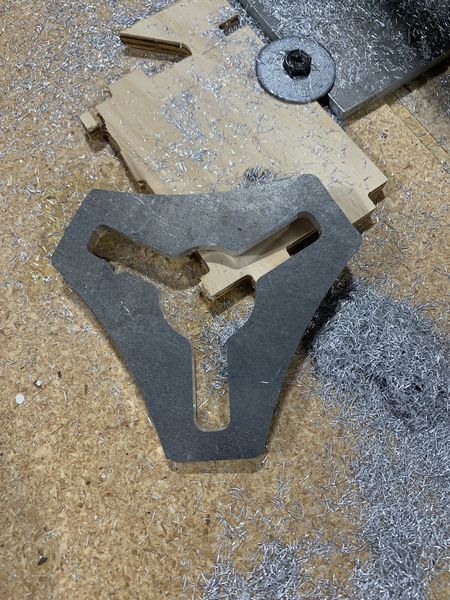
The XZ plates is where I have had a lot of fun lately. This is my first steps into cutting aluminum on my machine and I have learned a lot, as well as being totally impressed with what these machines can do. I used this great write up to help me get started -
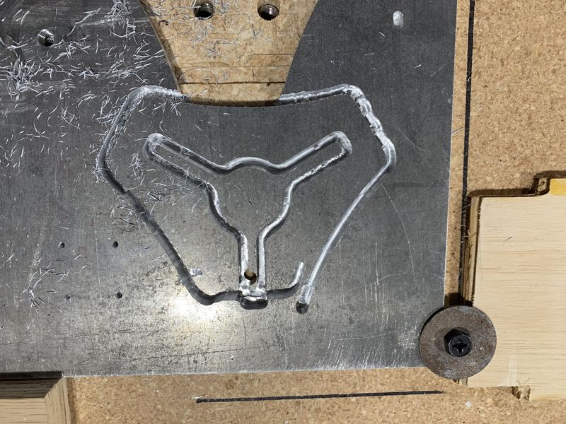
It got me a starting point, and I went from there. Did some sample cuts testing feeds and speeds. Lot of new items were learned around material hold down as well. I was able to get the V1 logo cut after a couple tries.
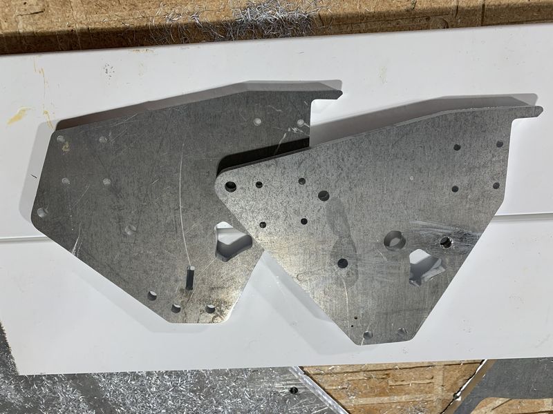
Got some settings I was happy with and started cutting the XZ plates. First one went well, but was a little short in regards to depth and didn’t fully cut it out. I was able to manually get the piece out and then a bit of sanding on the edges go me a final part I could use. Adjusted the depth of cut and tried to get the second one as well. Adding that extra 1mm of depth really messed up the cut and I ended up with some missed steps in the process, trashing the part. Had to slow the speed of cut down and was able to get the second one finished. I now have two XZ plates that are ready for a machine build I think.
I used Trochoidal milling with cut paths worked out in Estlcam. There were 2 tools used for this, a 1/16th bit and a 1/8th bit. Links are to the V1 shop, which is where I got these bits. It was a bit more expensive than I would have liked, as I bought two of the 1/8th" bits and due to errors on my side, ended up breaking them both. First one broke as I did a pause to try and get some screws in for hold down, wrongly it turned out. The second one broke right as the second XZ plate was finishing. Part moved due to bad hold down right at the end of the cut, bye bye bit.
The following speeds and feeds are for each bit but I did full depth cuts of 7mm on both of them. I had to slow them both down for that depth though. At a 6mm depth I was able to go a bit faster. I am using the Makita router and the speed dial is a bit under the 3 setting on the dial currently. It moved around between 2 and 3 during testing. As I list these I would say use them with a bit of ‘salt’, your mileage will vary based on your machine and bits and material and current barometric pressure, etc. etc. You get the idea.
For the 1/8 bit I am running at a feedrate of 6.7mm/s. Trochoidal stepover is 5% and width was 35%. I think I might bump the width a bit more on future cuts here as chips seemed to pack the cut curf a lot. This then packed in behind the bit I felt and sort of impacted the whole trochoidal side of things as the space for the bit to moved was now filled with packed chips. Think more space here might help.
For the 1/16th bit I am running at only 4mm/s feedrate. Trochoidal stepover is 3% and width is 50%. I didn’t have the same chip packing issue here and they cleared well. Granted I didn’t do as much cutting with this bit, more just drilling the smaller holes.
Both bits were plunged into the material at 90 degrees at 3mm/s. Still learning so I might have missed some items, but messing with these settings is what has allowed me to get the cuts I am getting. Hope it can help someone else, but the post linked above is probably a better place to start if your new over my minor notes here.
Another quick update and also asking for advice with an issue here.
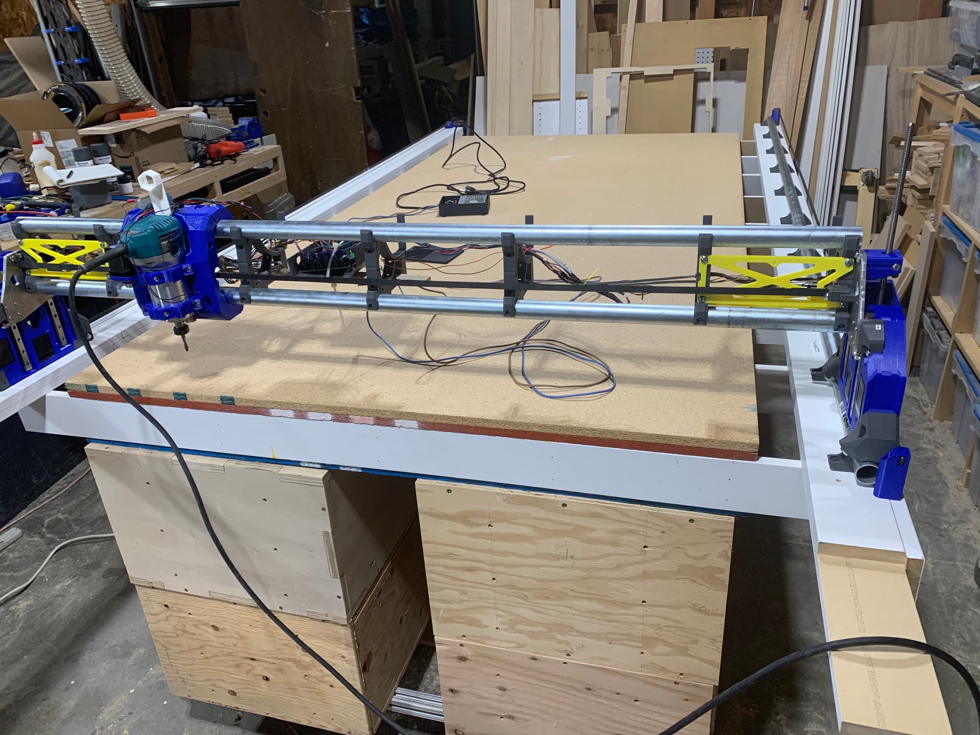
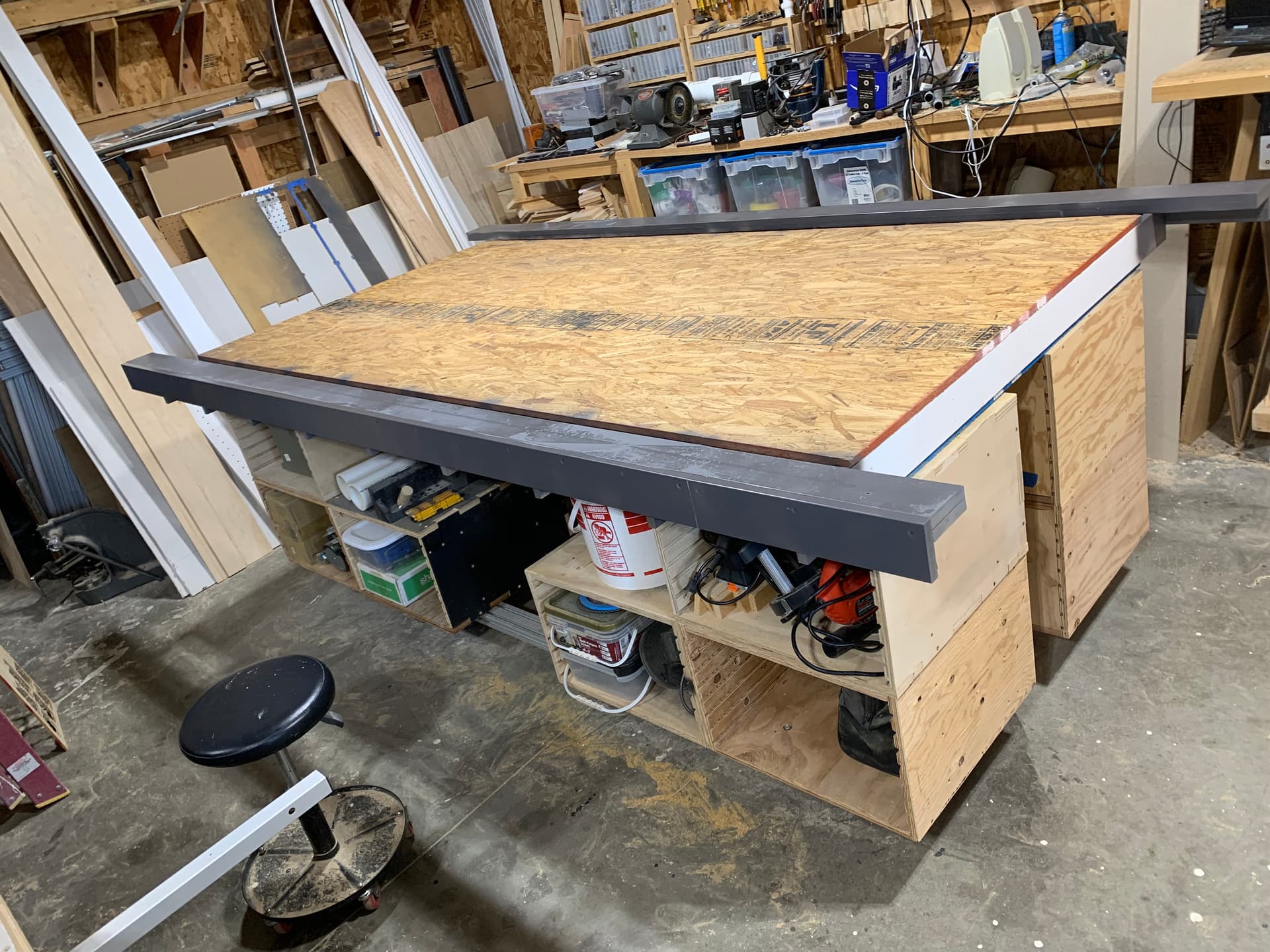
Was able to get the rest of the parts printed and started the process of tearing down the LR3 for the pieces to build the LR4. Was able to get the table for it flipped over and the top piece anchored down. Nice and rigid now at this point, and a great working surface for the build.
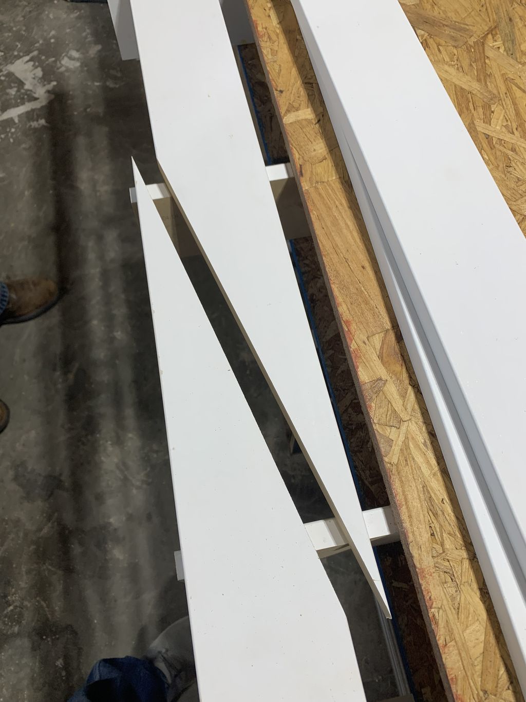
Have started the side rails for the machine to ride on, but they are just loose still so far. I couldn’t get 10’ MDF strips, so we are doing a scarf joint across two of the braces to extend two pieces the needed length.
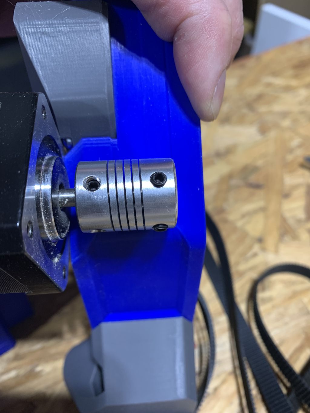
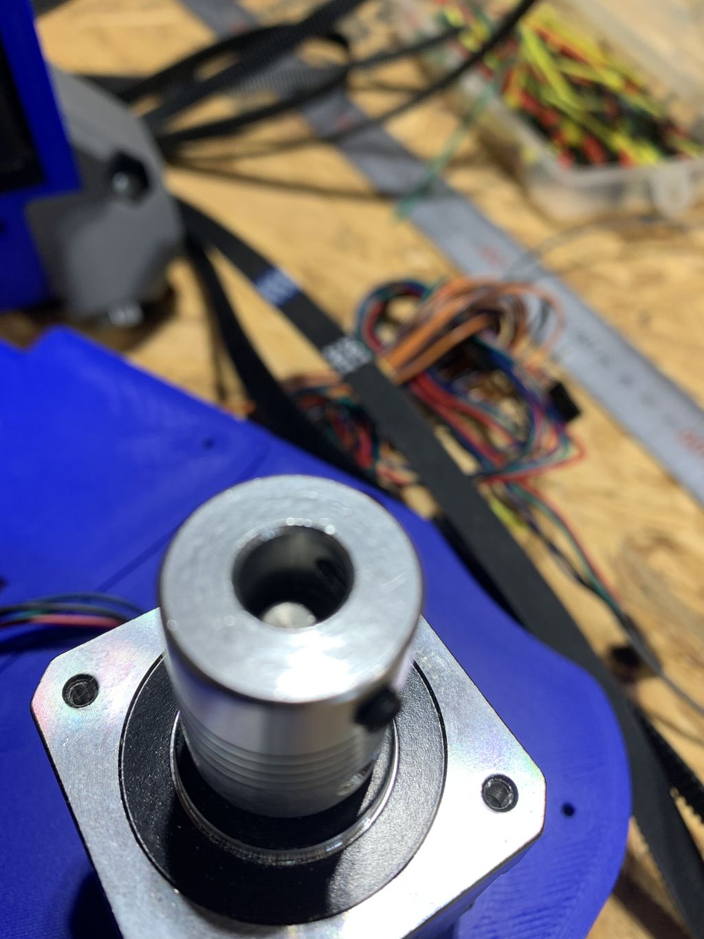
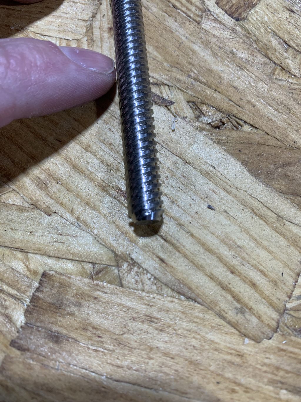
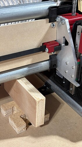
The area I am having issues with is the Z height motor, coupler and threaded rod. If I put on the coupler via the directions and the gauge on the YZ plate there is only ~6mm of space left for the threaded rod in the coupler. When I go to tighten the set screws on the rod it gets push up and out of the hole by a small bevel at the end of my rods.
My steppers were purchased via the V1 Amazon affiliate link but not sure where I go the coupler or threaded rod from. Not sure if this was from a friend or if from V1 affiliate link again, to long to remember directly. These worked fine on the LR3. Am I going to be ok to adjust the spacing of this coupler different than the directions? From what I can see the only issue is going to be that the bottom set screws can’t be accessed from the small access port on the back side of the YZ plates. Am I missing something else with this adjustment?
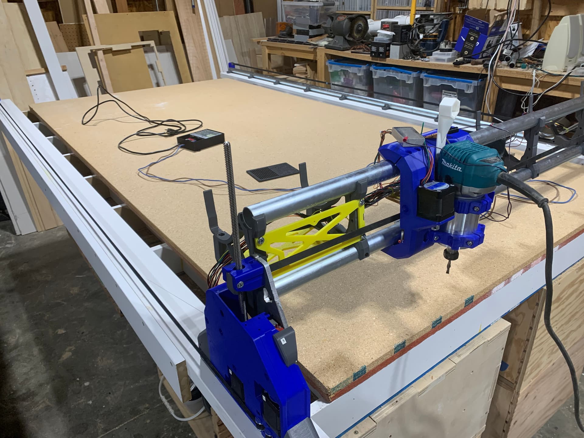
Hello all, just another update on my build process here. I have a machine up and sort of working.
Thanks Ryan for the pointers with the Z axis lead screws. I was able to grind off the rounded bit on one end and then it seated better in the coupler and I was able to anchor it down. I had some wiring issues as I had to extend my stepper and home switch wires, but have that sorted and it can be moved under control of the webgui. I was also able to home each of the axis’s and it was so cool to see it moving again.
Next task is to get it squared in and the Z leveled up. Also going to rework how the touch plate is setup. I have it hard wired in now and want to get it so that I can remove it when not needed. I have had it fall on to the job on my LR3 when in motion and don’t want that risk here.
Help…Something odd is happening here and I am at a loss. I am running the Jackpot controller and can access the web gui and jog the machine around just fine. I can home all three axis, no issues. I am working through the leveling and squaring and this is where the issue arrived. The issue is with the Z-Axis. When I home it the bar goes up and hits the Z0 and Z1 limit switches does the back off and retouch no issues. When I use the web gui and jog the Z either positive or negative the beam moves in the correct direction. My issue is with the z leveling process. I happen to have my touch plate hooked up and working so I figured I would use it, via the instructions here.
When I run the G38.2 Z0 command my beam goes UP looking for the touch plate??? It fails and the first time it happened it ran to the limit switches and the Z0 stepper seemed to release and that side of the machine dropped. I killed the power moments after that, so not 100% sure. I restarted the machine, releveled Z and ran the G38 again. The beam again went up but I killed the power this time before it hit the limits.
I have no idea what is happening here and this doesn’t make sense. How can I fix this? The Jackpot is from the V1 shop and came pre-loaded with the LR firmware and I haven’t touched it. Here is the ‘$$’ output on the card.
$$ Output
<Idle|MPos:0.000,0.000,0.000|FS:0,0|Pn:P|WCO:0.000,0.000,0.000>
[MSG:INFO: FluidNC v3.9.1 GitHub - bdring/FluidNC: The next generation of motion control firmware]
[MSG:INFO: Compiled with ESP32 SDK:v4.4.7-dirty]
[MSG:INFO: Local filesystem type is littlefs]
[MSG:INFO: Configuration file:config.yaml]
[MSG:INFO: Machine LowRider]
[MSG:INFO: Board Jackpot TMC2209]
[MSG:INFO: UART1 Tx:gpio.0 Rx:gpio.4 RTS:NO_PIN Baud:115200]
[MSG:INFO: I2SO BCK:gpio.22 WS:gpio.17 DATA:gpio.21]
[MSG:INFO: SPI SCK:gpio.18 MOSI:gpio.23 MISO:gpio.19]
[MSG:INFO: SD Card cs_pin:gpio.5 detect:NO_PIN freq:20000000]
[MSG:INFO: Stepping:I2S_STATIC Pulse:2us Dsbl Delay:0us Dir Delay:1us Idle Delay:255ms]
[MSG:INFO: User Digital Output: 0 on Pin:gpio.26]
[MSG:INFO: User Digital Output: 1 on Pin:gpio.27]
[MSG:INFO: Axis count 3]
[MSG:INFO: Axis X (3.000,1263.000)]
[MSG:INFO: Motor0]
[MSG:INFO: tmc_2209 UART1 Addr:0 CS:NO_PIN Step:I2SO.2 Dir:I2SO.1 Disable:I2SO.0 R:0.110]
[MSG:INFO: X Neg Limit gpio.25]
[MSG:INFO: Axis Y (3.000,2483.000)]
[MSG:INFO: Motor0]
[MSG:INFO: tmc_2209 UART1 Addr:1 CS:NO_PIN Step:I2SO.5 Dir:I2SO.4 Disable:I2SO.7 R:0.110]
[MSG:INFO: Y Neg Limit gpio.33]
[MSG:INFO: Motor1]
[MSG:INFO: tmc_2209 UART1 Addr:3 CS:I2SO.14 Step:I2SO.13 Dir:I2SO.12 Disable:I2SO.15 R:0.110]
[MSG:INFO: Y2 Neg Limit gpio.35]
[MSG:INFO: Axis Z (-297.000,3.000)]
[MSG:INFO: Motor0]
[MSG:INFO: tmc_2209 UART1 Addr:2 CS:NO_PIN Step:I2SO.10 Dir:I2SO.9 Disable:I2SO.8 R:0.110]
[MSG:INFO: Z Pos Limit gpio.32]
[MSG:INFO: Motor1]
[MSG:INFO: tmc_2209 UART1 Addr:3 CS:I2SO.19 Step:I2SO.18 Dir:I2SO.17 Disable:I2SO.16 R:0.110]
[MSG:INFO: Z2 Pos Limit gpio.34]
[MSG:INFO: X Axis driver test passed]
[MSG:INFO: Y Axis driver test passed]
[MSG:INFO: Y2 Axis driver test passed]
[MSG:INFO: Z Axis driver test passed]
[MSG:INFO: Z2 Axis driver test passed]
[MSG:INFO: Kinematic system: Cartesian]
[MSG:INFO: STA SSID is not set]
[MSG:INFO: AP SSID FluidNC IP 192.168.0.1 mask 255.255.255.0 channel 1]
[MSG:INFO: AP started]
[MSG:INFO: WiFi on]
[MSG:INFO: Captive Portal Started]
[MSG:INFO: HTTP started on port 80]
[MSG:INFO: Telnet started on port 23]
[MSG:INFO: Flood coolant gpio.2]
[MSG:INFO: Mist coolant gpio.16]
[MSG:INFO: Probe gpio.36:low]
ok
<Idle|MPos:0.000,0.000,0.000|FS:0,0|Pn:P|Ov:100,100,100>
$HZ
[MSG:Homed:Z]
ok
<Idle|MPos:0.000,0.000,3.000|FS:0,0>
Hello Jason, thanks for that info, that got it working.
Doing that command on one side of the Z beam gave the output of
[PRB:0.000,0.000,0.195:1]
and the other end gave me an output of
[PRB:0.000,0.000,0.450:1]
That means there is a difference of 255?? between the two ends? Not sure how to read that info. I also ran the commands more like the link I posted above, on the Z leveling, and did 3 Z probes on each end and then ‘?’ to get the MPos reading, think that is the one I need. One end got the following values for Z0 -0.055, -0.155 and -0.120. The other end of the beam, Z1, got the values of 1.05, -0.025 and -0.025.
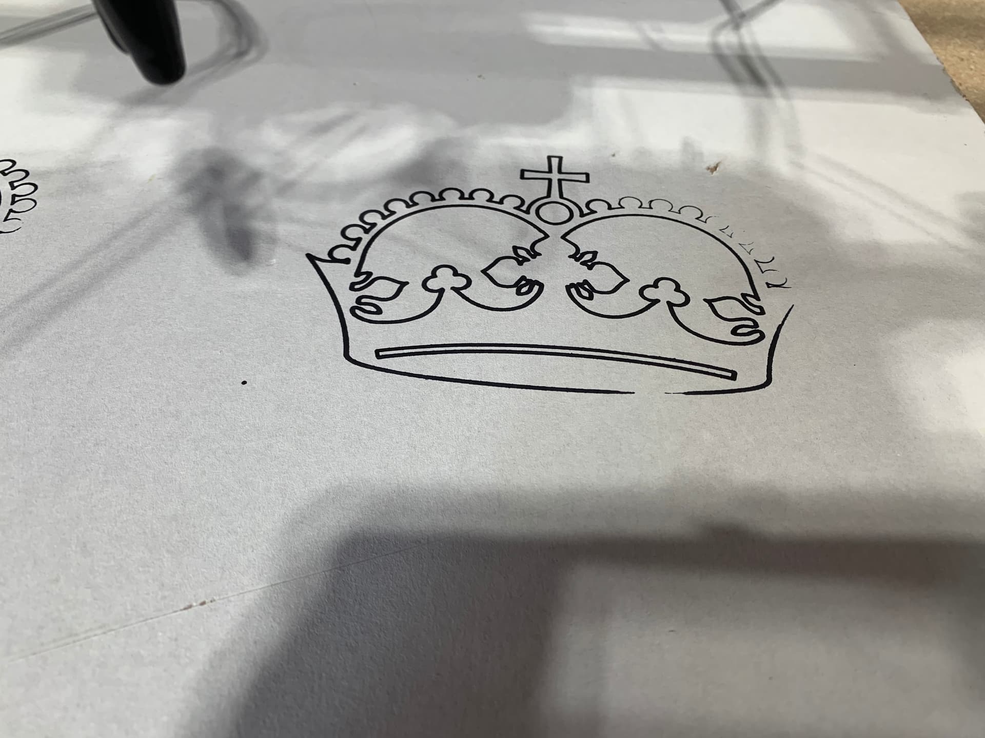
Not sure what the means. I think maybe the Z1 end is a little higher? But not enough to worry about, I think? That is less than 1mm difference? I did my first crown and the way it looks sort of supports that. You can see it get light on the left side. That is a piece of scrap drywall it is drawing on, if that impacts anything.
You should home Z $HZ between each probe. Otherwise, I’m not certain, but you might be stacking measurements. You should see much larger negative values this way.
I was confused that the probe offset was a bit different than the Z position but saw the same behavior. So, I learned something. The probe offset is the actual probe value. However, once the probe triggers, it has to decelerate so the machine position is a bit different. For me, that’s about 0.4mm. That has some implications for probe panel configuration but I’ll discuss that in another thread.
If the probe is successful it will issue a message like this [PRB:151.000,149.000,-137.505:1] with the machine position at the time of the touch specified. The 1 at the end specifies a successful probe. After touching, the machine will decelerate to a stop. This means the machine location will differ from the location in the message after the probe. It is usually only a tiny amount, but you should account for it. The over travel is proportional to the speed. It could break your bit if the over travel is high or the bit is very fragile.
Anyways, for purposes of Z leveling, it doesn’t really matter as long as you use the same numbers.
Once you get new numbers, we can sort out the adjustment. The first thing to know is which size is Z0 and which is Z1. For me, Z0 is on the left (looking at the front router side). But, it can be the other way. It just depends where you plugged in the Z steppers.
@ZzingG I was having a hard time leveling the z axis also. I decided to use a piece of plywood to level my Z0 and Z1. I lowered the Z0 down until the beam just barely touched the plywood and set my zero. Then I jogged over to the Z1 side and lowered it to zero. It was a little over a 2 mm gap. I lowered Z1 down until it just barely touched the plywood and added that 2.3mm to the Z1 pulloff. I restarted the Jackpot and used the probe on both sides. There was only a 0.3mm difference now. I added another 0.3mm to the Z1 pulloff and now it is level.
Hope this helps.
Thanks @jeyeager and @Britt for the tips. I think I have z leveled in now. I wasn’t running the Z back to home on my first try at this. I ran the home and touch plate probe 3 times on each side of the z beam and got the following.
Z1 - -62.115, -62.540 and -62.540
Z0 - -62.105, -62.275 and -62.440
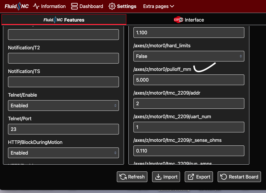
I also did it with a thicker block so it didn’t move as much and Z0 was -42.005 and Z1 was -42.235. I adjusted the Z Pullback in the config and change it down to -3.6 and both sides are now almost the same. I ran the crown again and it was much more consistent in what was drawn with the pen, down the point that I think it was the material I was drawing on this time.
The way I am understanding the Z pull back is that is seems to adjust only the Z0 pullback? There didn’t seem to be a way to adjust the Z1, or Y1 for that matter. There wasn’t any settings for the A or B in there that I saw, and I believe those are the channels on the card.
Been a little slow on my side with other life items needing a higher priority, but figured I would put out a quick update. I have torn the machine down and am working on rebuilding it with my newly cut and painted final strut plates.
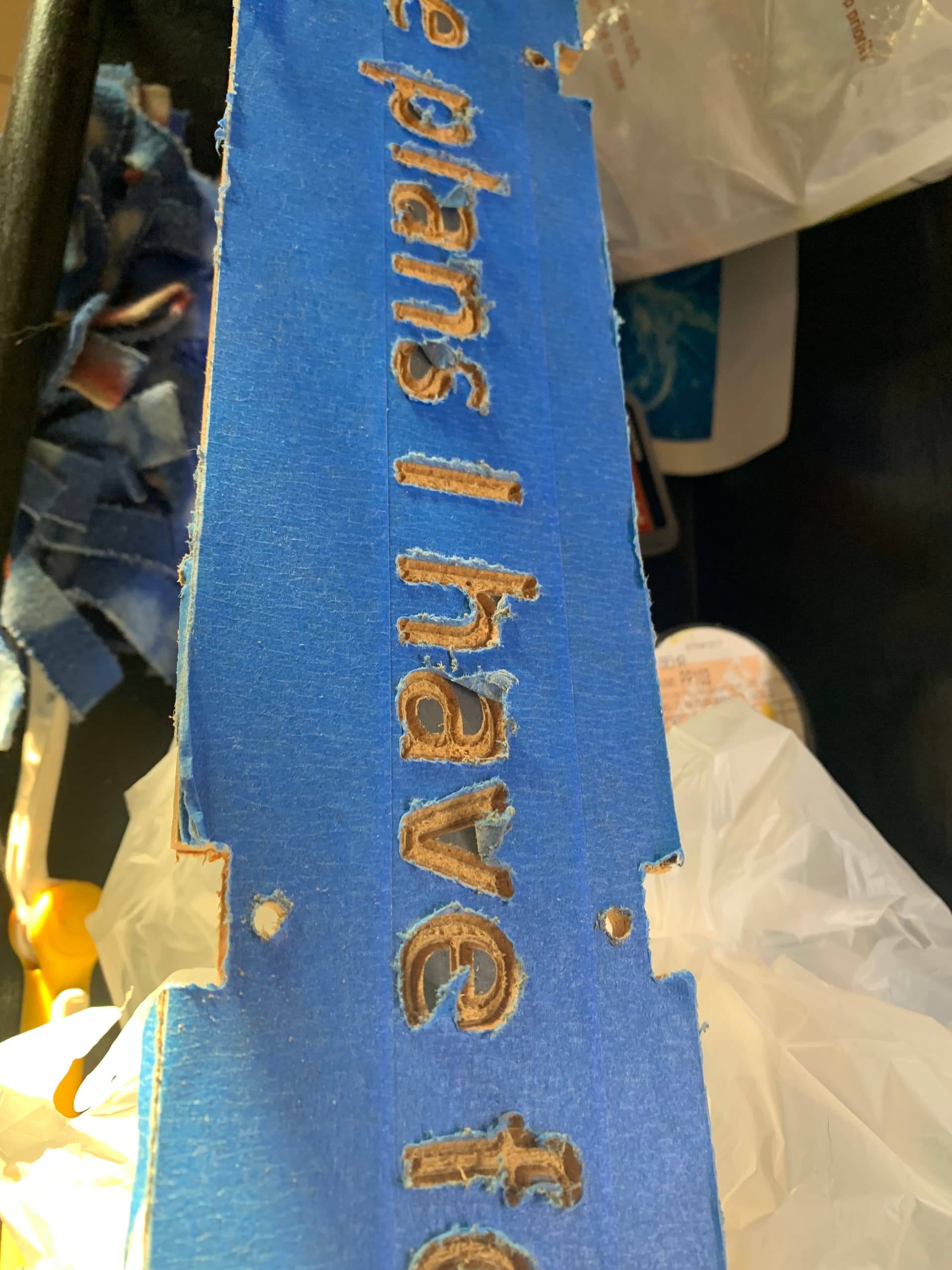
I was hoping to get fancy here and painted the base color before I did the cuts for the lettering. I then covered it in tape thinking that it would just cut the tape away and I could then spray paint the lettering. That didn’t work as well as I was hoping it would. The tape tore and got pulled up all over the place.
Ended up doing all the lettering by hand with a small paint brush. Not what I wanted but I like the final look. Also working on the table and painting the runners and sides of the table.
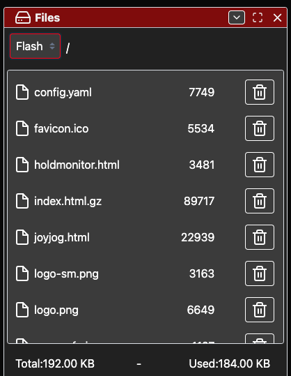
@Britt I haven’t done any config past the web interface. Where are these config files at? Is this from the jackpot website? Would this count as a ‘firmware’ update, in that I change the file and upload it to the controller to change its operating characteristics. I have been working on the physical machine mostly and haven’t done anything with the controller really. It came flashed from V1 and just using it like that so far.
I have done something like this before. And found that using blue tape like that doesn’t work well. But you can get “contact tape” or vinyl that will work much better. Just make sure your first paint layer has completely dried before you apply it. This will stick much better and leave a cleaner edge. Also make sure you are using a real sharp bit. I always used a brand new bit for this. Cuts much cleaner.
You can download the config on your Jackpot and edit that. Just be careful not to add any extra spaces or your config won’t load. Use a basic text editor like Notepad. Once you have saved your changes then you need to upload it.