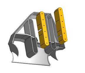
I agree, we need a “Fallout”/Cyber punk style lowrider ![]()
I also love the idea… I’m also keenly aware that the external control box is photogenic, and provides an iconic point of interest for my LowRider. For mine it serves in a way similar to how the iconic “double kidney bean” grill serves on a BMW. From an engineering prospective, inside the beam makes sense. From a PR perspective, the loss of visibility means a LowRider could stand to have “something else” to serve visually as a point of interest. I know the core is another possible focal point.
I’d suggest you instead do heat-inserted knurled threaded inserts. In my experience, nuts in capture slots don’t have enough grip to have them all serve effectively for more than about one or two uses.
Wow! Love love love
Good thinking, but since I’ve got all the braces printed, it might not be possible any more as the holes are too small - I’ve never had a problem with captive nuts, nor with epoxy, but I do like the thought of heat inserts.
Thanks for that - I need a bit of time to set up some tidy photos and I’ll upload the STL and DXF to printables so anyone can chop, paste, laser or engrave their own version if they wish.
From a PR perspective, the loss of visibility means a LowRider could stand to have “something else” to serve visually as a point of interest.
I can’t agree on that one - the plastic box sitting on a few angle brackets doesn’t do anything for me - and I think it will clash terribly with my fenders which will be two-tone - I understand that’s all the range back to the future! ![]()
From a PR perspective, the loss of visibility means a LowRider could stand to have “something else” to serve visually as a point of interest.
Your neat logo and space-age looking end covers (fenders) could serve for focal points.
As indeed will the stunning work at the end of the whizzing spindle! ![]()
I’m not sure how much longer this little work window will be open for me and I’m spending way too much time staring at a blank computer screen and I really should do some other things but here’s this morning’s update anyway-
Not a lot of progress on that package, just want to share my pain, remembering that time for me starts a day earlier than for most of you ![]() . I have to stress this is no-one’s fault. After clearing Australian customs, parcels can arrive within minutes, or sometimes they take the scenic route.
. I have to stress this is no-one’s fault. After clearing Australian customs, parcels can arrive within minutes, or sometimes they take the scenic route.
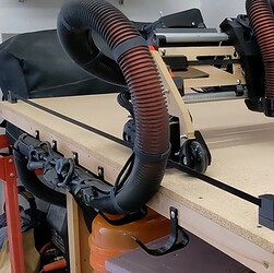
Now a question for @vicious1 Ryan - I have always liked your vac/cabling solution, but haven’t noticed it implemented anywhere else - it looks great in the vid, but how is it in real life? I am considering a version with a “gutter” in the table rather than the printed hooks. The only improvement I think would be to put a largish radius on the corner where the vac hose rubs just to stop it catching?
I don’t want to grumble but even though USPS tracking shows my box in Sydney, I’m pretty sure but the way the colour is starting to creep back into my life, that it’s not!
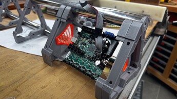
Also the board mounts are going to work - they’ll be a bit fiddly to assemble, just in terms of sliding bits of plastic on and off the tubes to set them up, but nothing too serious. Thanks again for the idea @Fabien !
I’ll upload all this stuff to Printables in a day or week or two, in case anyone wants to adapt or make something similar. I think the in-beam mount for the new smaller board will be a doddle. it’s so tidy in practice that I’m also thinking of going back to my original plan and mounting the power board and a plug for the router in the beam as well. Sorry @vicious1 , the logo vent is facing the wrong way at the “other end” because: laziness, but it’s going to be pretty much nothing more than a splash of colour in the beam.
If I were to do this again, I wouldn’t bother with the mounting holes, I’d just make blank tabs (maybe a little wider) and drill them in place.
I thought it might be cool to use those little rubber fan mounting things but I only have three in stock and our local electronics shop wants $4.95 EACH for them - so screws it is!
That looks so fancy!
I am super happy thus far, and really looking forward to having it running, I might just squeak in the “fender” prototypes this week, probably no hope of getting it all finished but it will look terrific sitting on the bench in my absence!
Of course I am printing a catapult at the moment, distracted by a flock of pesky ducks! ![]()
![]()
![]()
(Thanks for that!)
Oh, and I know I’ve tagged you to the point of distraction - but two posts up - how did the vacuum hooks work out on the table edge?
It worked pretty well keeps all the load off the machine. I want to now try it in the table itself. To keep the footprint down. I think it will work great on the rail side, I have it ready to try in my parametric table. If that isn’t great I would try an angled pocket next, instead of the hooks.
Thanks. Yes that’s what I have planned.
You have a week to test it for me! The reason for the question is that I am also entertaining the possibility of running it on the rail side, in the table, between the rail and the belt.
I know what you are thinking : “Dude, you’ve only got 57mm clearance to fit a 50mm hose, what are you on? !!”
Hmmm… just watching your vid, the hose wants to topple over and constantly catches on the sharp corner of the table. I think that can be fixed by rounding the corners, making a taller rub rail (with rounded corners), making the pocket deeper to hold the vertical part of the hose more vertical, or a combination of all three in conjunction with a permanent bend to accurately guide the hose.
The bend can either be a PVC plumbing part or a printed one, or a “splint” on the hose, but “maybe” if the pocket is deep enough the hose will be self supporting over that height.
I am pretty sure it won’t work well enough to keep the hose off the belt, because it’s just too squeezy but it will save an easy 100mm of footprint.
What are you thinking by “angled pocket”?
Basically what I have now on an angle. But I think the table pocket/channel is going to be best.
Looks awesome!
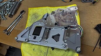
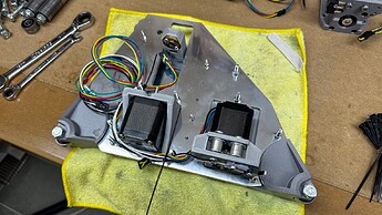
I started a complete dry build today. I know that most LR3 builders just assemble the thing and start making stuff with it, but it’s probably time to defend myself once again, and for the benefit of those just jumping on to this thread I’ll reiterate that building this is my hobby (for now) as opposed to using it. It is my classic car if you like. It’s a “pastime” as things like this were once called, and it is passing a fair bit of time I have to say!
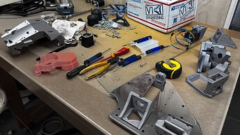
There are already a few obvious changes to be made - I have to nut out which steppers go where for instance because I went a bit overboard on the LR2 and some of the wiring tails are a little short one end, and I’ll give the bits of the metal that we can see a final detail when it’s apart - it’s just too difficult to protect it and build it when there’s so much going on first time round.
On a somewhat bright note, I was a bit dubious about the accuracy of some of the laser cut holes, but they’ve all been fine. I ran a tap through the M3 holes on the rails and while some of them aren’t quite vertical they’re close enough for now and will only need a small drill to ream them out if things need adjusting.
I haven’t cut off any of the bolts as I am waiting to see if I can get the “fenders” to work. I had wondered if I should cover up all that stuff, but with the polished plate it looks even more “back of house”! ![]()
![]()
What could possibly go wrong?
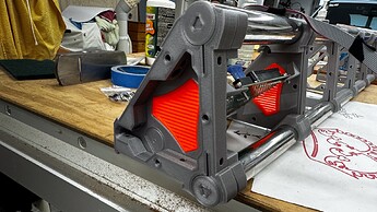
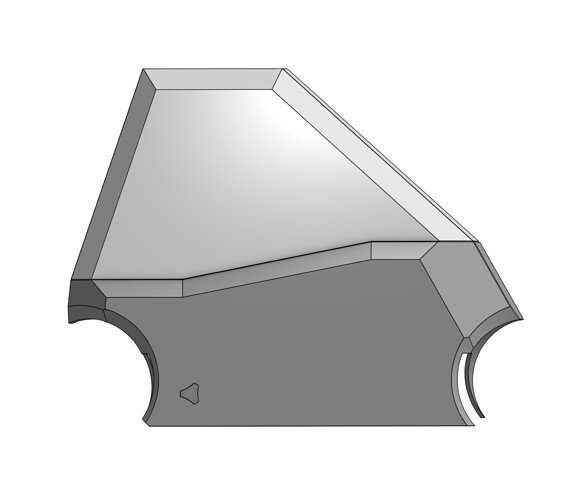
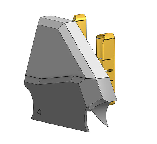
After a day pretty much running errands, I have got the first cut of the fenders pretty much ready to print.
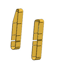
I’ll print the clips out of PETG to give them a bit more flexibility and the covers out of PLA. I had always intended the top half to be painted a light cream/off white but may yet do them in the same silver as the temporary braces. They just bolt to the rail bolts with captive nuts. I think I’m more concerned with taking them off than keeping them on, but I can always snip off a few clips if that’s a problem.
I’ll print a couple of test slices tomorrow, so if any of your fresh eyes spot some anomaly, or change that needs changing please let me know.
PS - I know about the cable entry - will wait till I have the prototype working to decide the appropriate routing, but I’m pretty sure it will be exactly on the join to the two halves (which I plan to keep separate parts).
Lovely!
Wow! Nice design!
Purdy!! I couldn’t do it though. All that work you have put into those aluminum plates I would have to keep that visible! And for me i just love the look of the 1/2" acrylic. So much so that I ordered more to cut some for my big LR3 lol.
