He’s using ribbon cable, @jono035, do something! ![]()
5 Likes
I love the thought of that. The new board I am working on fits nicely as well. If you add some sort of access point, or be sure it is easy to get to and the wires are long enough to do so that is the best place to put it. I don’t mind it being a little extra fiddly to not have the board on the back forever. I have been thinking about a parametric case to screw in and act as the last strut with a lid. Then you can either, custom cut one brace, or just cut off the last section.
3 Likes
If a 3 sided ‘Strut’ case width is 180mm (give or take brace width), then the Struts could always be cut width wise for any LR3 build?
2 Likes
that could work, take the calculated width minus case width and get a new strut
2 Likes
With case width intentionally being same width of the Core for that LR (give or take brace width depending on how the case and Strut are mounted/married)?
Some/all case panels cut with the CNC (by the builder) instead of more time consuming 3D prints, that’d also need to be packed/sent?
1 Like
No you kinda need a box for the board on the first build so chances of that being user cut are slim. I will be shipping an external mounted box for the Jackpot…maybe it can have the option of being tucked in the beam as well if the user chooses, if there is a way to still access the MicroSD.
1 Like
I love the idea of having it in the beam.
Idea: meld the box with the second from the end brace, so that brace prints extra tall. Leave it open ended towards the cap (probably no parametric adjustments needed) and position the board so that just removing the one cross brace from the end gives access to the board. Channels for the wire can go ro the rear bottom of the beam to feed to the hose hooks. One custom cut brace for the back, or just be careful when wiring it. Less user interaction with the CAD for the same clean look.
3 Likes
That could be easy. Brace and an endcap.
1 Like
Thanks @azab2c and @SupraGuy and @vicious1, it’s nice to know there’s a bit of support for the idea. (Not that I wouldn’t proceed if there wasn’t! ![]() )
)
I intend to epoxy-fix all of the beam nuts into the braces. Hopefully this will make removal and replacement of the strut plates relatively simple (vac hose and mounts notwithstanding) - my original intention was to use the bottom plate for access, but that had the potential to get really messy and inconvenient.
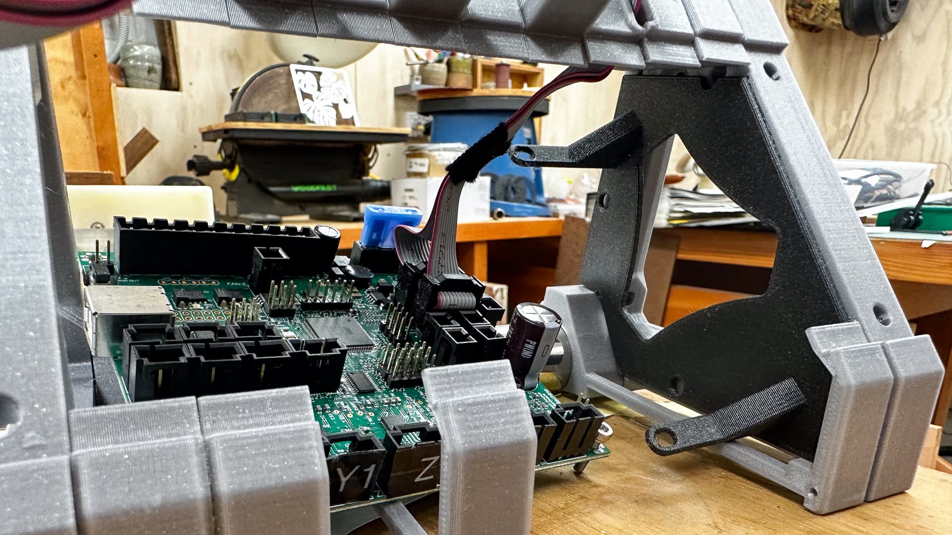
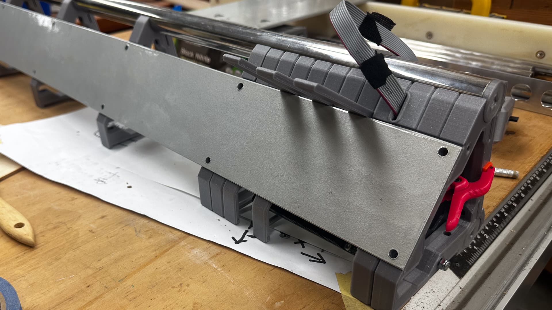
This thought is where I started. I came up with the “lego” system, because it’s vaguely parametric and adaptable by a combination of and , and it’s easy to make custom penetrations (like the one for the ribbon cables). FYI - the parts are connected with a piece of filament threaded through the little holes.
The Endcaps are not drawn yet, just waiting to finalise the wiring penetrations in an elegant way but will hopefully just clip into the braces.
I am hovering between making a slide-in mini patch-panel in the strut for the cables (power, YZ and USB) or simply running them through penetrations in the bottom parts as I have done for the ribbon cable in the top. That would clash with the vac stuff, but could also be a very tidy solution.
This is all just the first iteration. I’d normally work these issues through a bit further before publication, but I appreciate the feedback.
2 Likes
Yeah, sadly. I have the ribbon cable on my SKR Pro screen, too, despite being the cause of immense emotional distress.
Jokes aside, there are better products than I’ll ever design out there that are crammed full of ribbon cables so who knows ![]()
2 Likes
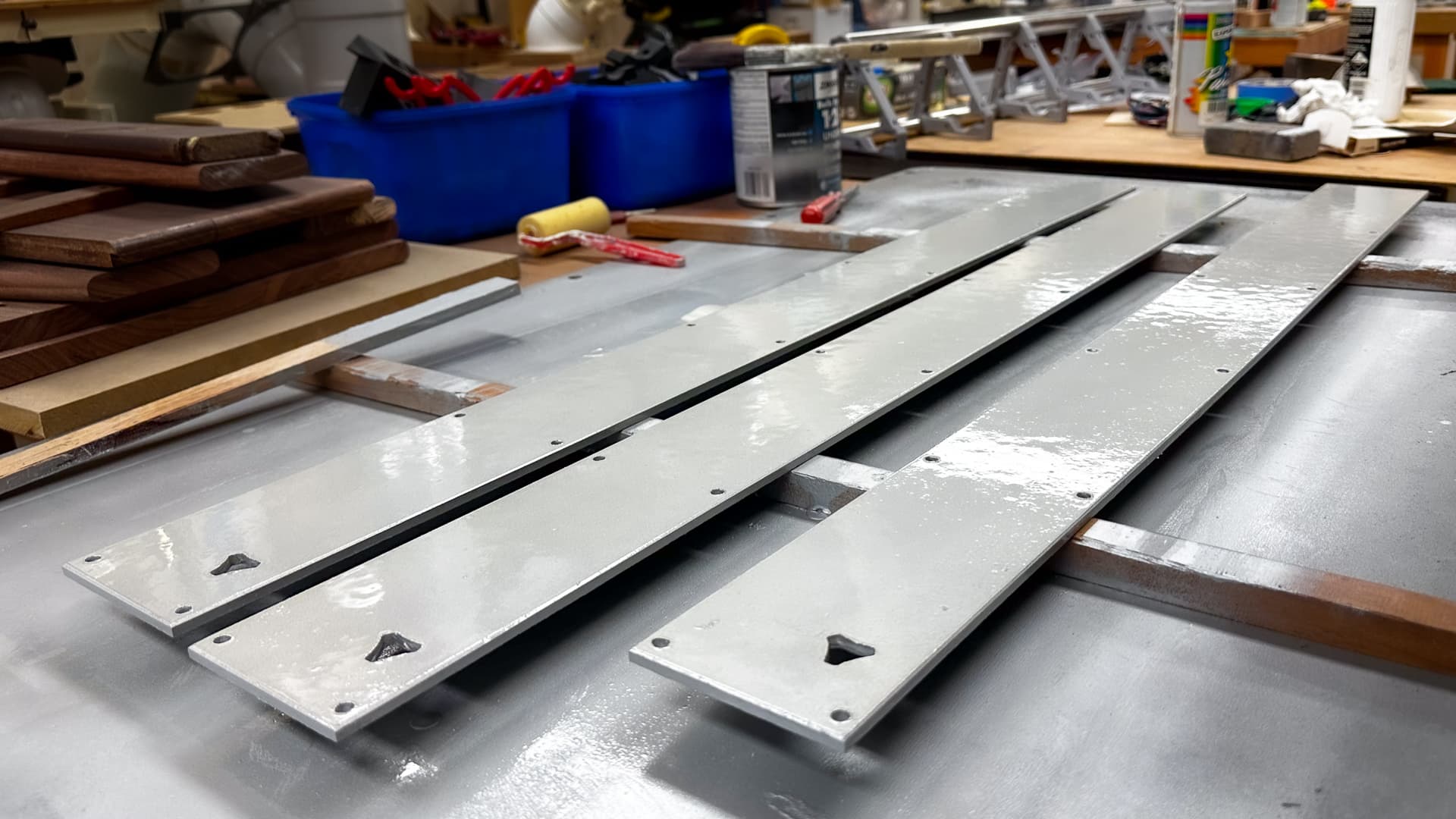
I didn’t do too much today.
I brushed two coats of sealer undercoat over the silver on the beams last night, and a light touch with 400 grit paper before four or five coats of silver and four of clear from a rattlecan.
Most of the furriness has gone, and now I just have to wait a few days for it all to cure before I give it a rub with 800 to see if the paint is thicker than the hardwood fur. If it is, happy days, I’ll squirt on a top coat and give it a buff. No need to go to too much trouble because these are the temporary and the one on the right, with the most damage, will go on the bottom.
I will continue with my dummy assembly once the bolts arrive, and once I can get some final measurements will try to get the “fenders” done while I’m still in a painting mood.
See @pony1023 , I really do share your pain! ![]()
3 Likes
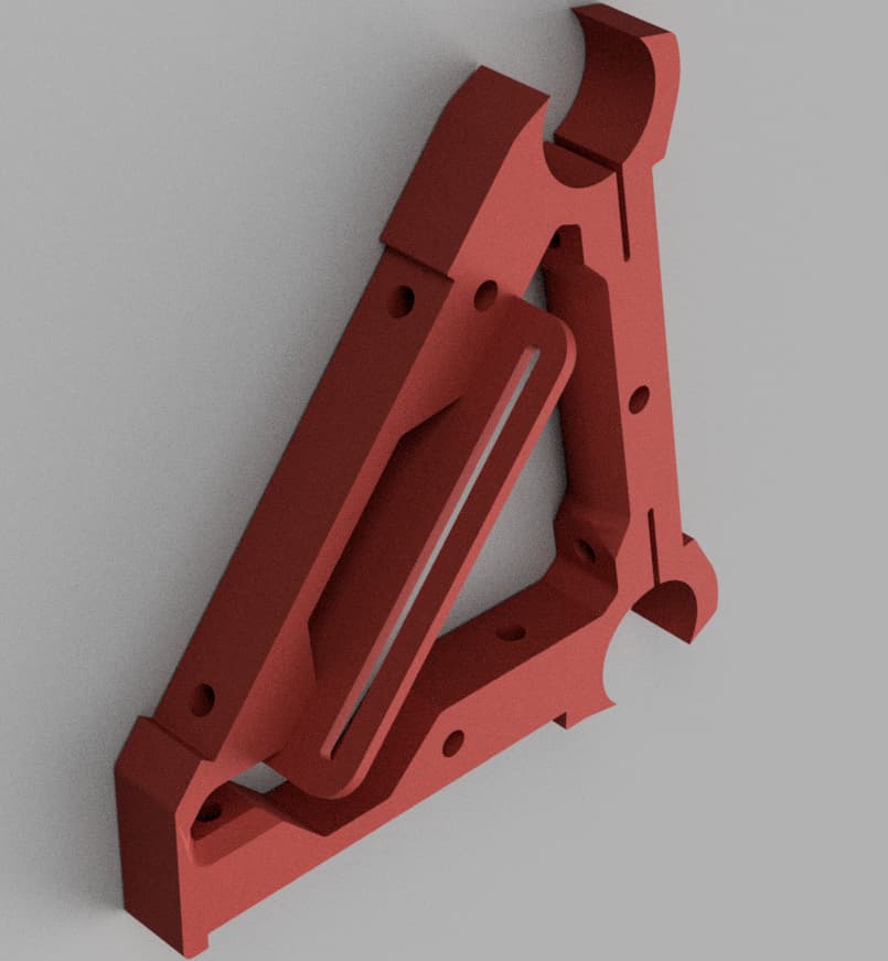
Maybe an idea for mounting the board(s) inside the frame
This is just a modified brace that includes a track/slot on the side
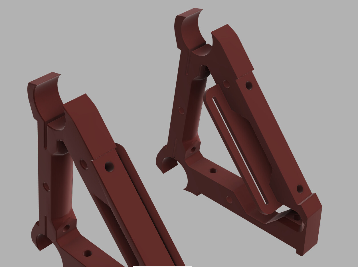
Print two of these in mirror, and adjust the distance between them to fit your board
The second one would be an additional brace, not bolted to the struts (unless you customize them) serving no other purpose than supporting the board
The supplementary brace accounts for X disance between mounting holes of the board
The slots account for Y disance between mounting holes of the board
It’s simple, and using both of thses features, you can mount virtually any board inside the frame without customizing anything…
This is just a quick mockup, you’d probably need to make the slot sit more in the middle of the brace, and maybe add a bit of clearance between the side of the brace and the slot
But I think you get the idea…
2 Likes
Thanks, that’s a great alternative mount!
A version of that would work quite well, particularly if the board was small enough. I think you could easily cantilever those brackets far enough to cover a standard span and make room for cable entry - I think I’ll have a play with some brackets that bolt onto the ziptie holes.
Actually - we might be able to combine bracket with end grilles here…
Hold my Beer!
The Rambo Board is a struggle to fit through the beam space in my current config, but my original intention was to fold down the beam over the front face (I need to draw it to explain) which would make access much easier.
The box sketch in the above post show the barest minimum clearances for the Rambo Board but the new brackets are on their way…
1 Like
When I was in year three at school and every year thereafter, I received a report card that read “nice kid, but easily distracted”.
Times don’t change, and having read the entire thread on the new control board, and realising I probably want one because it’s new and shiny and has a picture of a crown or three on it, but I have no idea how it will change my life, I have come up with a new plan.
Sadly this looks very much like the old plan. Continue the build as is, and in the unlikely event that it’s ever finished, look into it then. That decision means I don’t have to worry too much about ease of removal of the board - some disassembly will be required, and a version of @Fabien 's bracket is underway.
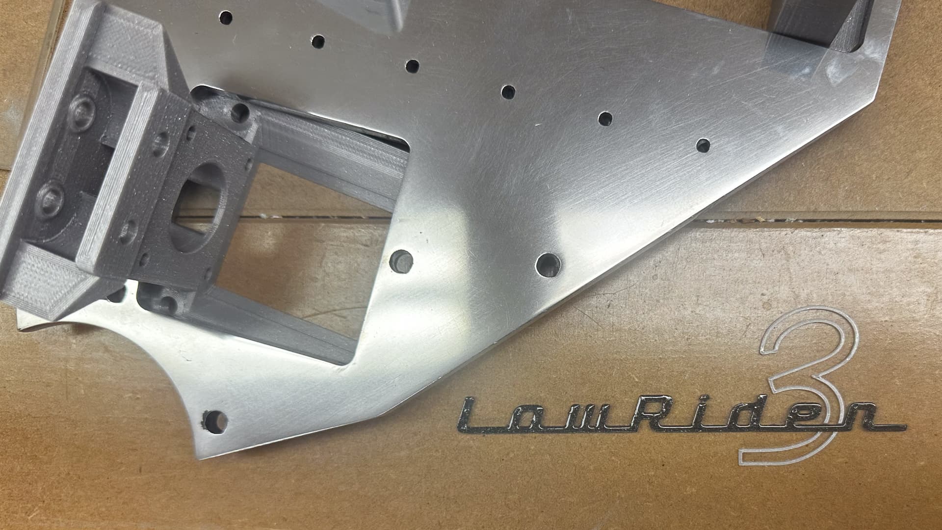
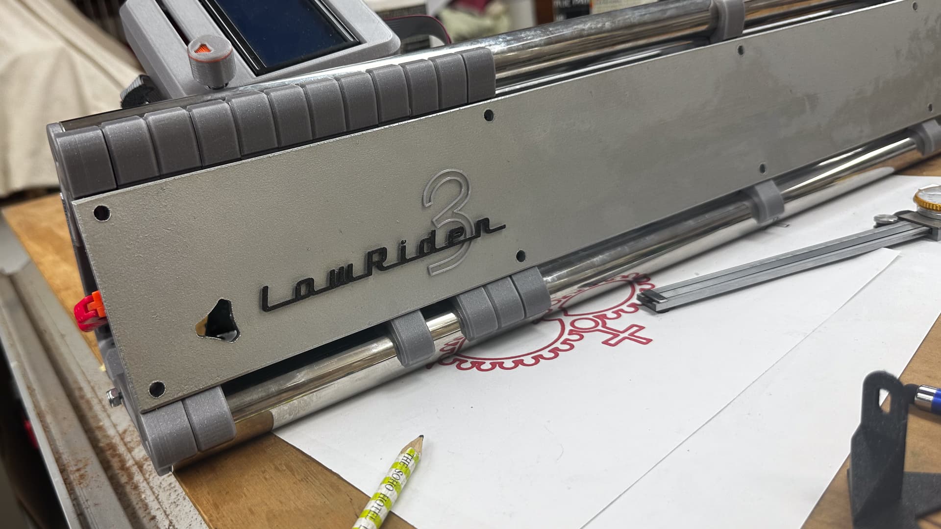
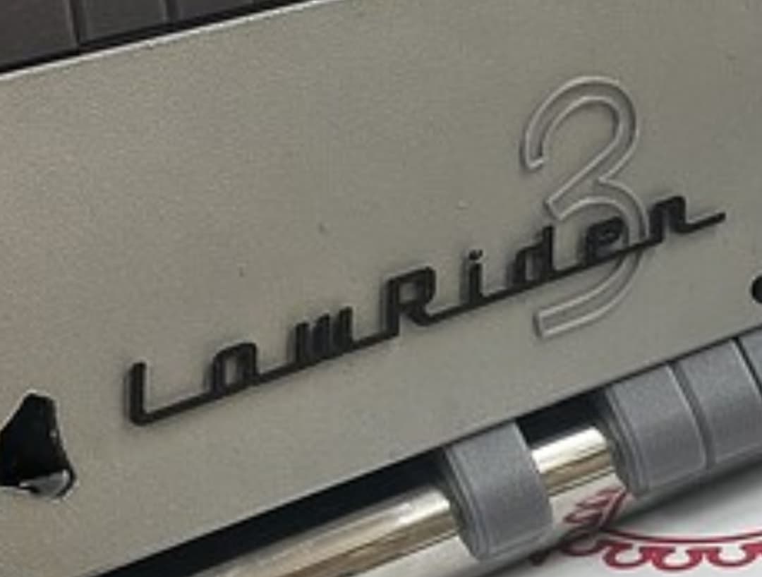
Naturally it wouldn’t be progress if I hadn’t made something pretty, and wasn’t fretting about final polish on the aluminium bits. The badge is 2mm thick, was intended for a 3mm composite strut - I wonder if it will clear the core on with my temporary hardwood ones?
3d printed with six or seven coats of clear acrylic.
6 Likes
I think it is a good plan
2 Likes
Much as I’d love to be able to understand what you blokes are talking about (and USPS’s tracking come to think of it) at my core I’m an Apple and Prusa kind of guy. ![]() As you know, my part of the game is in the pretty details not the tech stuff.
As you know, my part of the game is in the pretty details not the tech stuff.
I have no need that I know of for a change, but when it’s ready to be spoon fed, you can spoon feed me the update! ![]()
1 Like
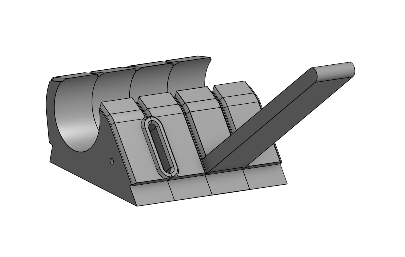
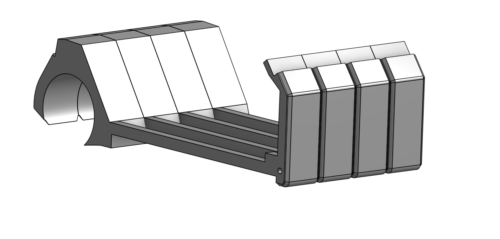
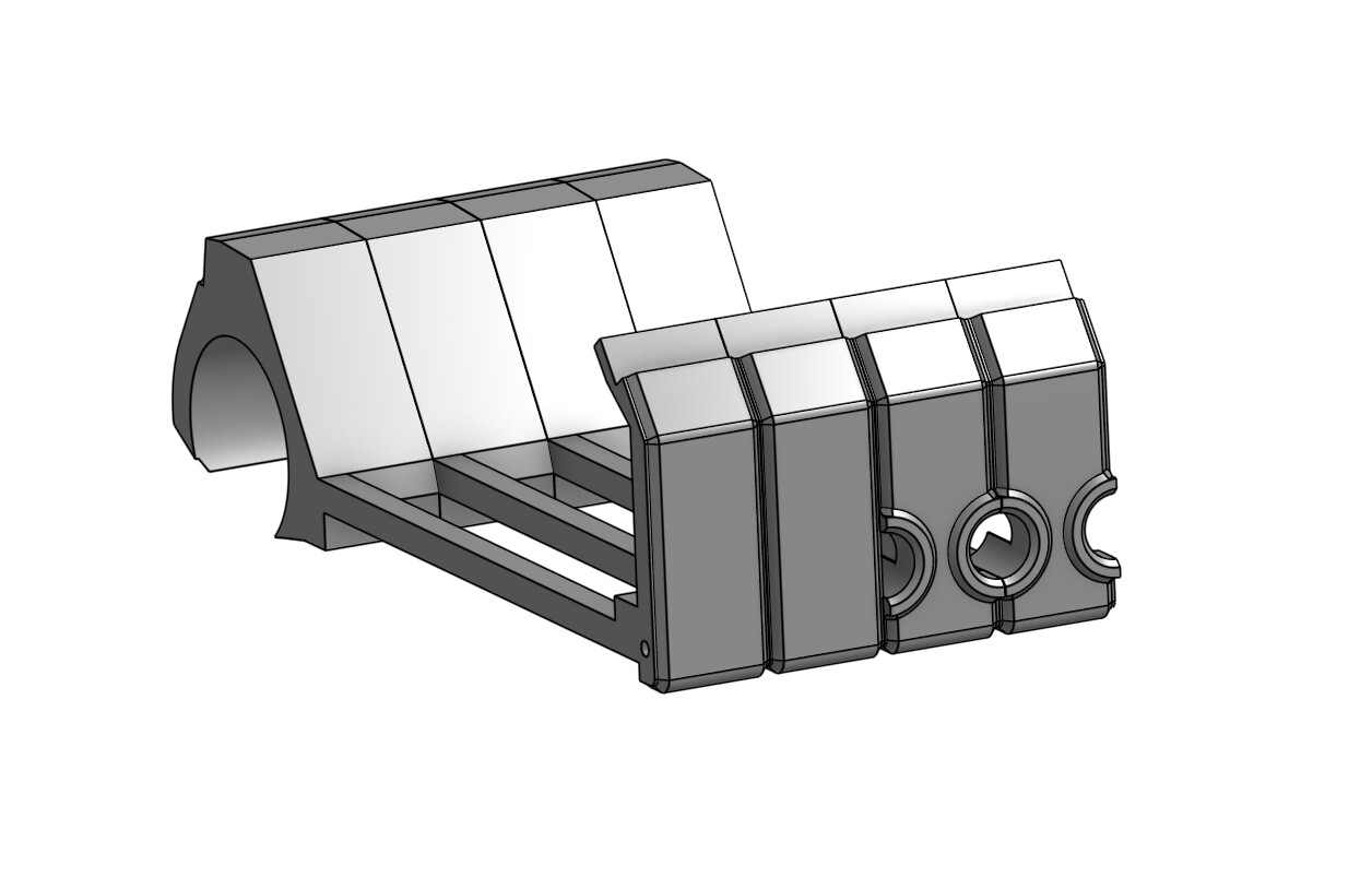
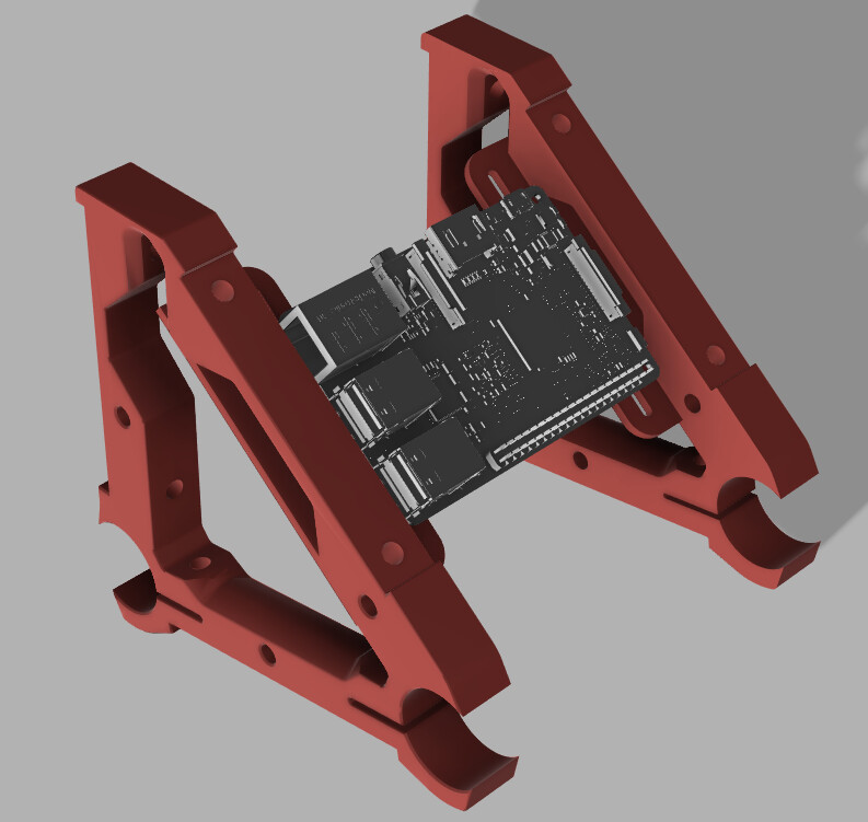
Thanks very much to @Fabien who sent me off in different direction as far as mounting the board goes, which also got me slightly distracted looking at different boards and board sizes.
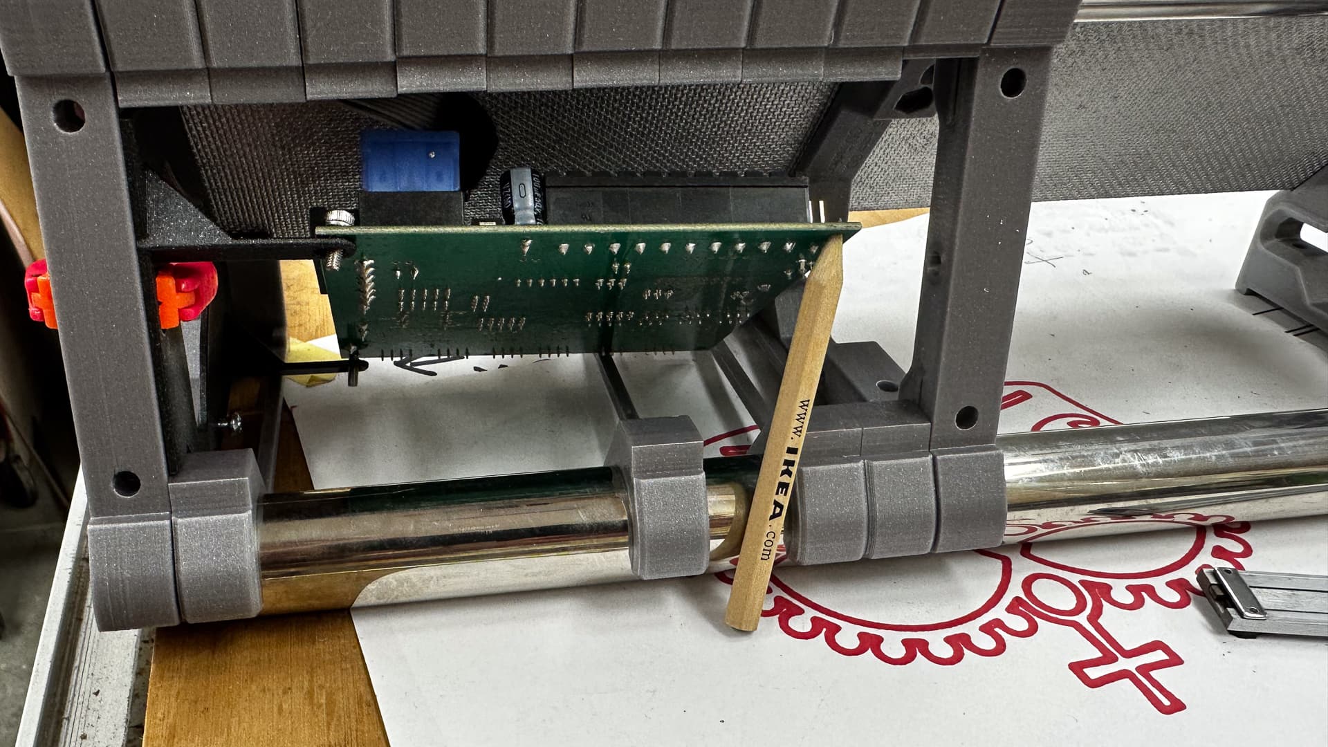
By creating a separate “gable” end panel, for any different board it’s just a case of making the stand-off distance parametric and there’s plenty of room for cabling, ventilation and a pony even, but it’s a tight fit for the Rambo! I probably won’t go for the IKEA pencil mount, but I am tempted.
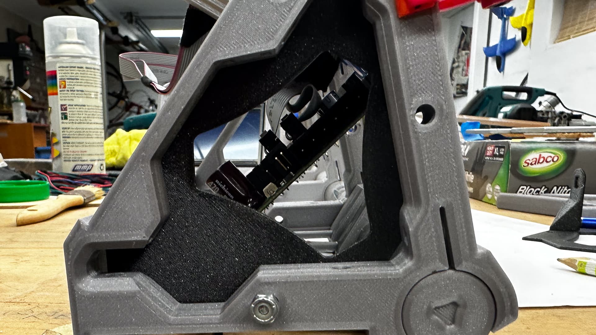
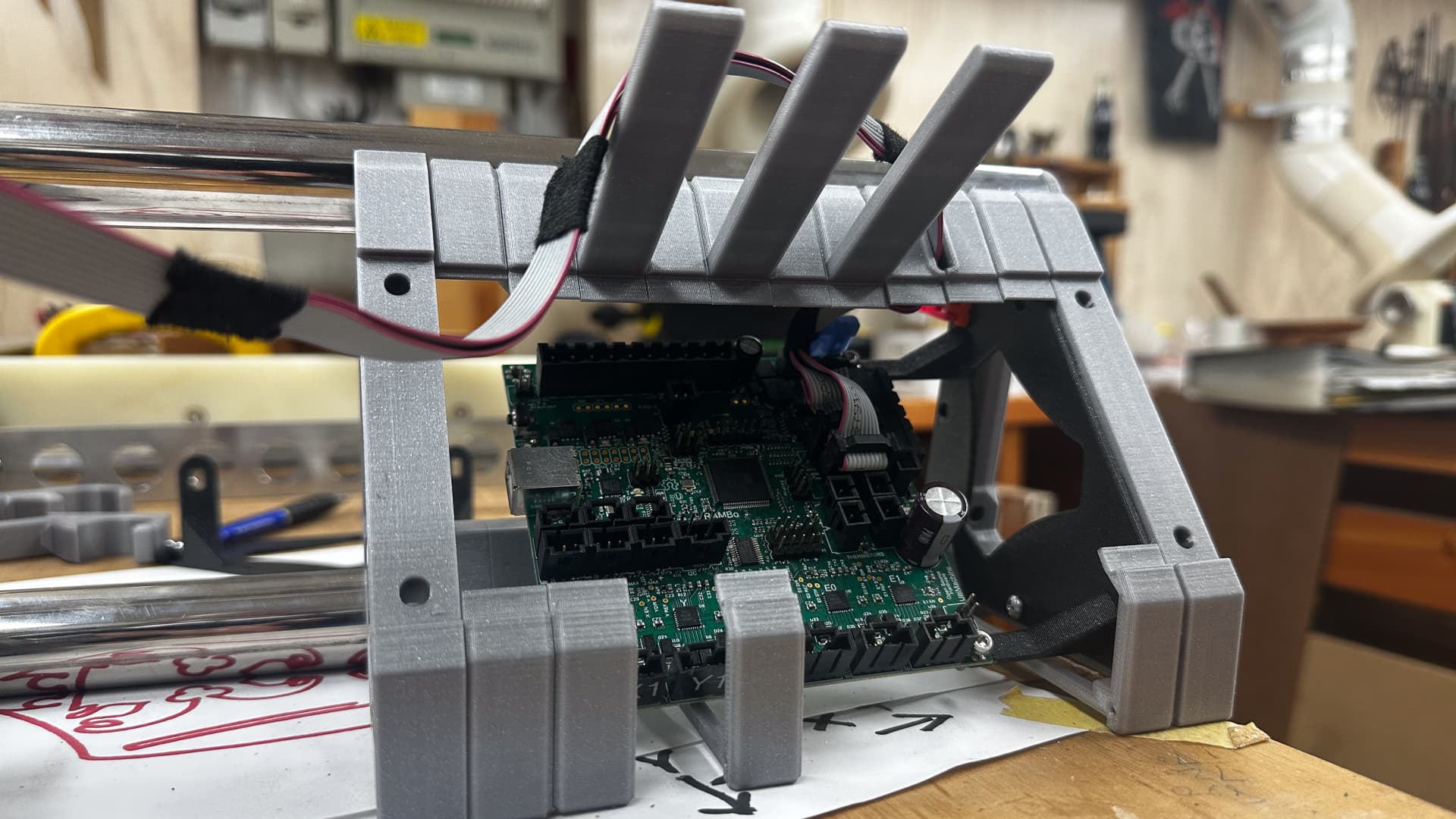
If you stand back and squint and ignore all the missing bits on the bottom you’ll get an idea of where I’m going with all these odd bits.
6 Likes

The problem I’m seeing here is that you need the spacing between the first and second braces to be a multiple of the brace’s width, otherwise you’ll get a hole somewhere… or need to print a customized one which kinda defeats the purpose…
I do like the “baffle”/“gabble” idea though, looks like an easier way to add the support than re-printing the braces
Cool logo BTW ![]()
3 Likes
Actually infill pieces are easily variable and just string onto the tubes. Just divide the clear dimension by the number of parts you want to make and there’s the height of the print. In a day or two I’ll make that a bit clearer - but they don’t even have to be parametric these days with most Slicer’s “dimension” capability -or just change the Z in the slicer and it all works.
I looked at a few ways of encasing the board, just liked the appearance of this one as it matches the fifties futuristic look I’m trying to capture.
3 Likes