I was expecting both, to delineate the VMOT outputs.
Hmm, interesting idea. I am not sure if I can actually get the black ones without buying a full quantity of them. So it is a giant, maybe. I used them here because the footprint is just a hair bigger, so both will work If I want to swap them.
Yeah, just barely. That blocks a lot of the antenna and the mount screws would need to be small enough not to get in the way.
2 Likes
Just wanted to poke in and let @vicious1 and the brain trust know that I love these threads.
Great work its appreciated!
5 Likes
Thanks, it is fun, but I have no idea what I am doing so I need babysitters to make sure I don’t get into too much trouble.
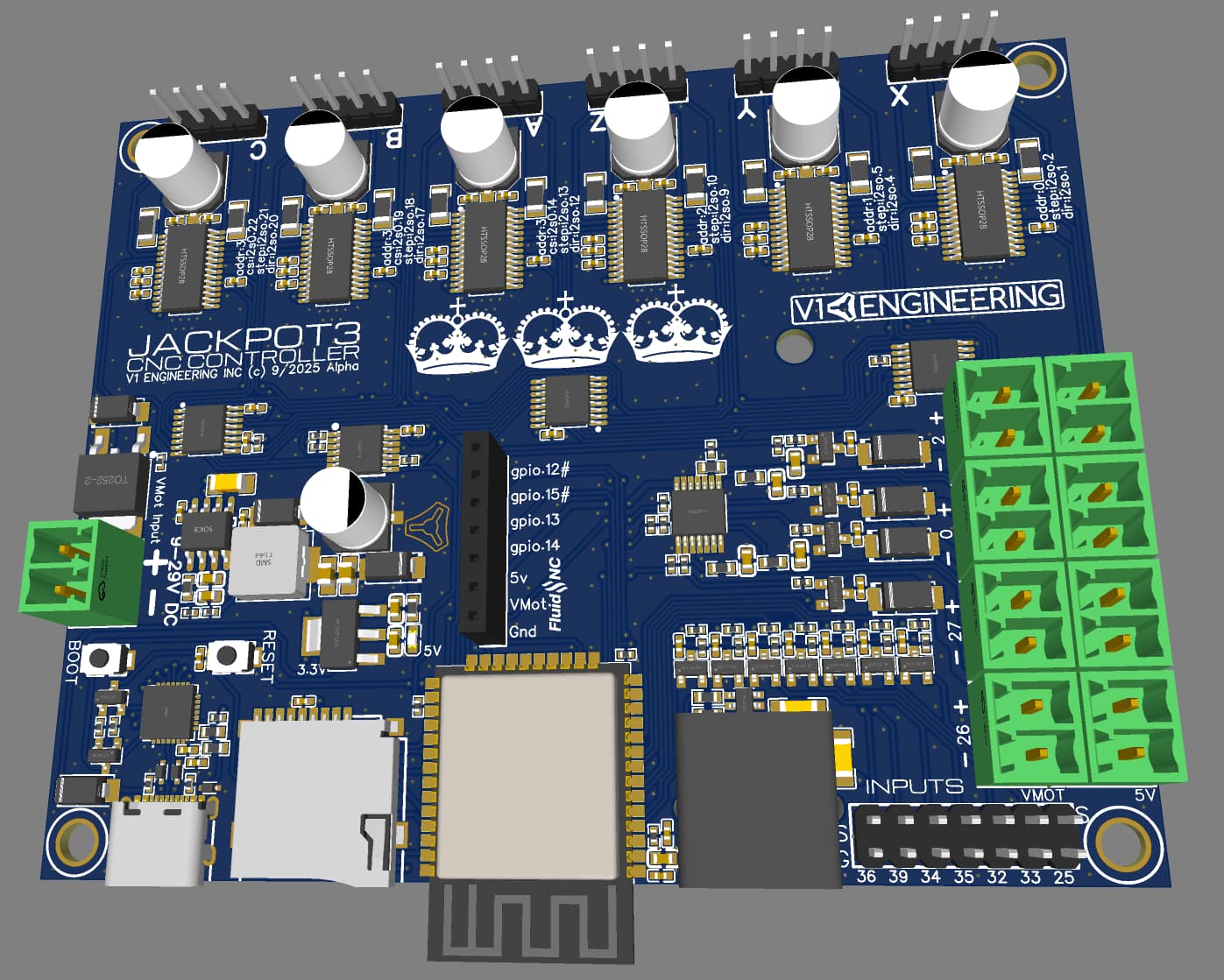
I also went back to the large diodes, they are more efficient and not nearly as close to the edge of the capabilities. When those others got hot, I took a closer look at the spec sheet, these are better.
6 Likes
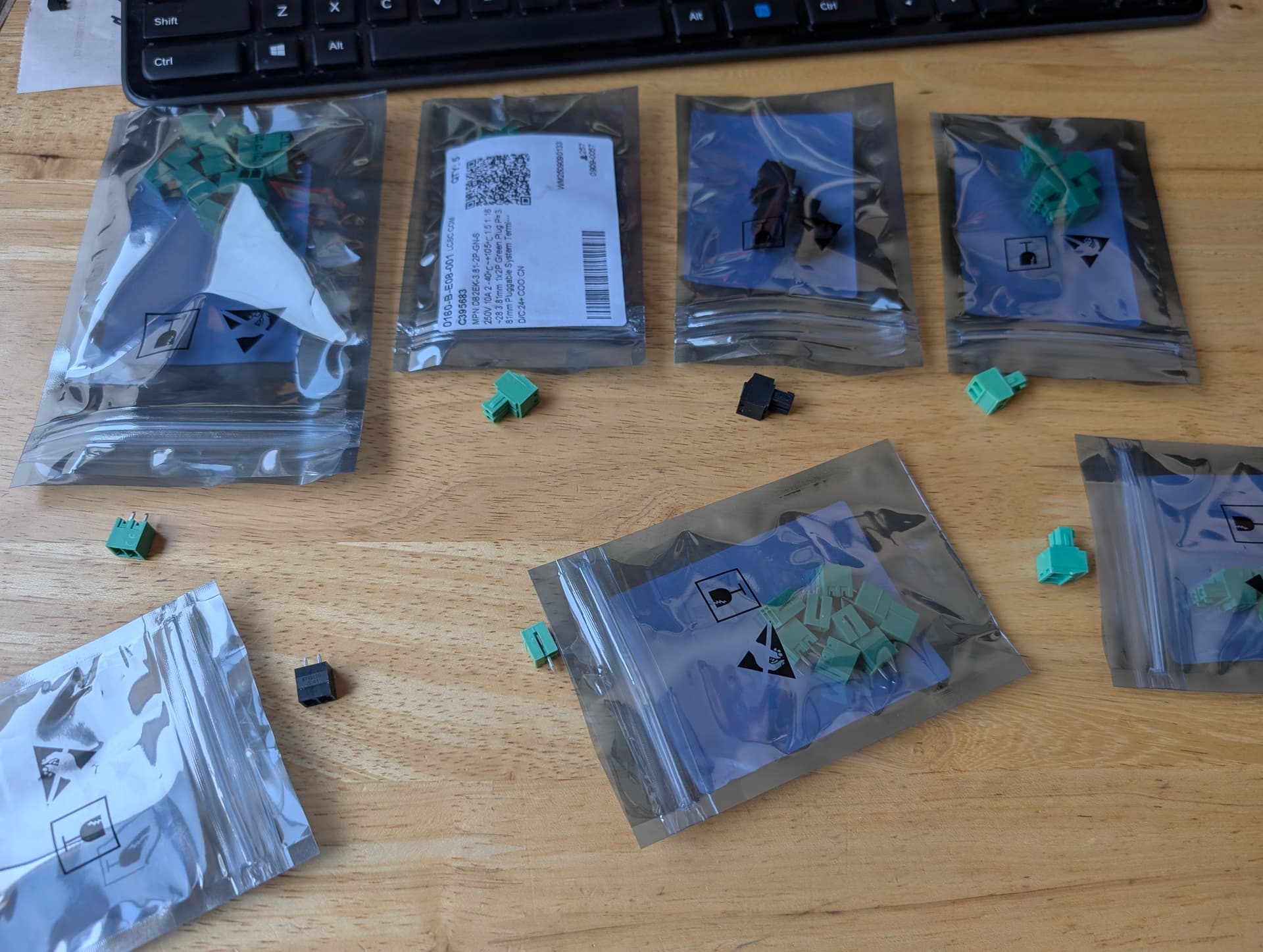
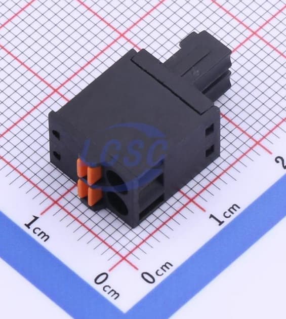
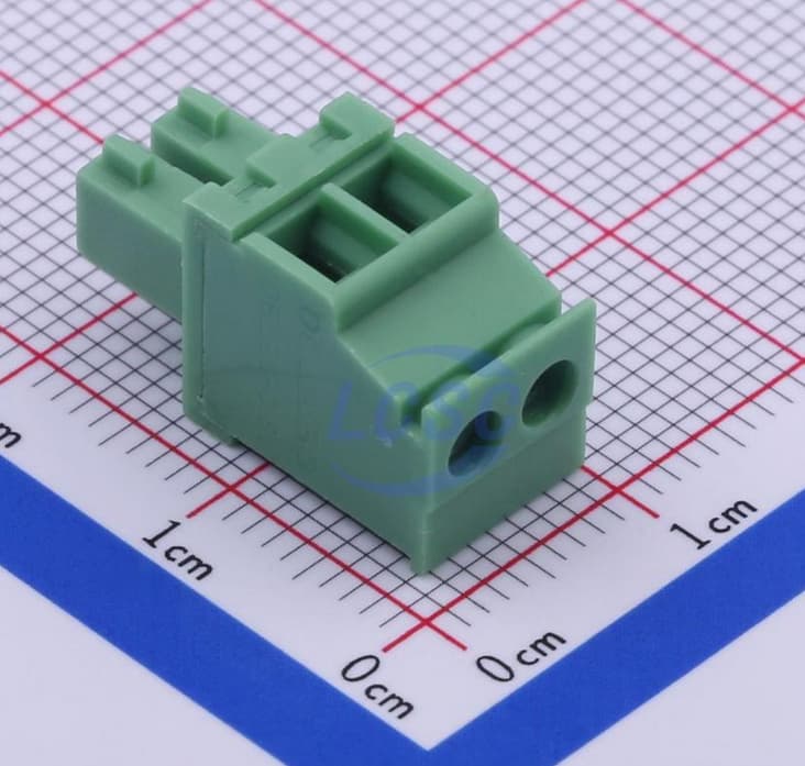
If we have to use plugs, I really like these plugs. Smaller than the old molex style, wire clamps are great, and the plugs are tight but not too tight.
1 Like
I would prefer the wires to exit at the 90 degree angle but they seem to be a lot bigger, they do have some in push button though. DB2EKD-3.81-2P-BK | DORABO | Price | In Stock | LCSC Electronics
Dorabo, 3.81pitch.
1 Like
what size wires do they accommodate?
Happy with the cost and clearances within the printed enclosure when everything’s wired and connected?
Sorry if people explained already, if the wires need to be manually fed into the connectors, then, am curious how this overall solution ends up better than regular 3.5mm or 5mm pitch screw terminal blocks?
@vicious1 thank you for sharing your process, thinking and journey as you evolve and expand your CNC/Multipurpose Controller board options.
16~28 I think it is wider than that.
320V 8A
They are shorter than the JP1 and heatsinks, including wires.
The socket and plug are 1.5mm taller that the jp1 uart headers on the drivers. So smaller than they look.
When you use the screw to clamp the wires you are not torquing the solder joint, and plugs mean you are not fishing wires around the side of the board.
I have created a business that relies on me continually outdoing myself. I learned very quickly the only way to do that is get help. You all provide so many different perspectives, and make it more fun.
3 Likes
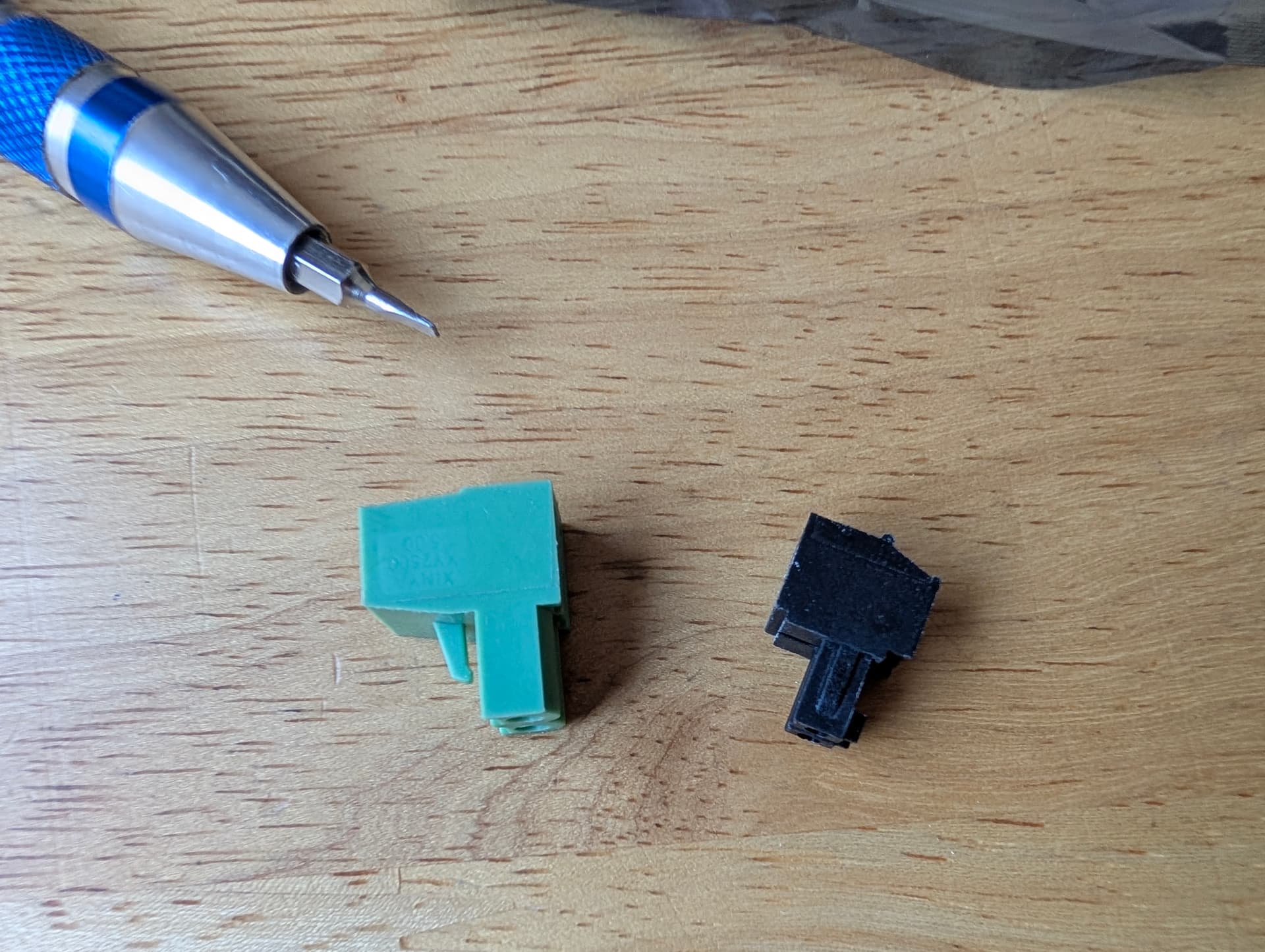
I always thought the black ones were bigger… ![]()
Serious comment: I like the ones you can screw in. Those push thingies are finicky.
1 Like
Yeah, the push ones are way too stiff and very expensive in comparison.
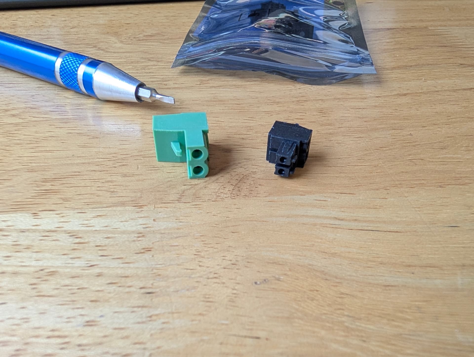
As for the screw terminals, these have like the elevator box that moves, I really prefer these, super easy firm grip wide opening. The ones on the JP1 are the screw that pushes the metal sheet wedge, those were easy to miss a wire and people would really crank them down, then they would not open back up right.
I am pretty confident you guys will like these.
4 Likes
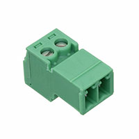
It looks like these will only fit one at a time on any given output (e.g. VMOT or 5V) dure to interference. That’s certainly fine as you’d only want a single output voltage for any given output.
Do they fit side-by-side without interference?
(Can you put a full set of VMOT all along the edge without interference across them?).
Do the lock tabs interfere with the VMOT connectors when installing to the edge (5V position?)
Yeah, that’s the one. The corner frequency of that as a filter is 1.1MHz, rise time of 330ns. That means that 1.1Mhz signals will be reduced by half, roughly speaking, anything below that will be left, anything about that will be successively reduced in output. A fast low to high transition will take 330ns to get 90% of the way there.
! The pluggable screw terminals! Be still, my beating heart ![]()
So the idea here is that you’re only ever using the ‘top’ or ‘bottom’ row of those headers, right? The plug overhangs the housing in both directions. With most of the series I’ve used before having them side by side like that should be fine, though.
There are a couple of companies that do their own version of those headers, I think Phoenix was one of them, but the style shown there is by far the most common in my experience. The LPC series mentioned above should cross-mate perfectly fine.
Which pitch are you using? The one pictured is the 5.08mm where you have 3.81mm pitch on the PCB. The 3.81mm pitch version of the LPC should fit fine.
Rising cage terminals. That’s why I use them and recommend them. They work well with stranded wire, solid wire, ferrules, multiple wires in one terminal etc. The falling foot or bare screw terminals are infinitely worse. I’m still kinda unconvinced by the wago style terminals. The good ones are great, the cheap ones are kinda finnicky.
They should do, in my experience. They might take pliers to get in and out, but usually the plug doesn’t overhang the header. We had them side by side like that within 0.5mm of touching on our control boards at the last job.
That’s a fair question, for sure. The main draw in the applications I’ve used them in before is that you can unplug them to replace the board, take it away to modify it, flash it etc. or even just unplug something to disable it temporarily. Aside from that, it’s a lot easier to wire things up when you can have the wire and plug separate and then just plug it into place, especially if you’re working in a tight enclosure. Where possible you’re always better off making wire harnesses separately and then assembly is just plugging things together, it’s much easier to be neat, tidy and ensure things like all strands are in the housings etc. As Ryan says, you’re also putting all the force into the housing itself as well, not into the solder joints. And, worst case, you just leave the plug in and treat it as a screw terminal anyway, which is what we do sometimes, although I generally try to avoid having headers vertical on the PCB like that, I much prefer the right-angle headers aligned along the edge of the board, that does tend to set/grow your board size quite often, though. Lastly, often PCB mounted screw terminals are a lot crapper than the terminals in these plugs, the plugs are almost always rising cage type where cheap PCB screw terminals can be a really mixed bag and are often the ‘falling foot’ type just due to how they need to be made to stay compact and have a pin coming out the bottom.
3 Likes
That’s the reason why I opted for the Open CNC Shield 2 Mini again instead of the “official” Klemmenadapter XL for Estlcam. The Mini does not offer me any advantages for my next CNC, but it has the plugs and not the fixed screw-in terminals. I just love the ease of switching everything around. ![]()
1 Like
Yes, no problem.
These do not have lock tabs.
![]()
Yes. No way to use both at the same time. Just in case someone wanted to try.
Yeah as I dug further down the list I eventually saw the right ones. Fany phoenix are an option!
I figured they had a name. These seem to be the best screw terminals I have used.
3 Likes
Yeah, they’re by far the best in my experience. We usually don’t even use the expensive phoenix ones or whatever. We had a stock of Wurth ones from way back but I think any stuff I order personally is On Shore Technology from Digikey. Presumably any of the Chinese suppliers will be similar.
There are a couple of neat things that you can get with them as well. I’ve used PCB mounted plugs before for a product line, although the specific ones I needed were to match with a specific Weidmuller shape of connector, on a 3 month lead and couple $k MOQ.
That’s the general idea, it’s a bit tough figuring out what to call them and they’ll always be a little more expensive due to being more specialist, but that could give you some ideas for addons or adapters etc.
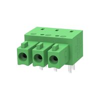
Another thing that I find super useful are the terminal block headers.
I don’t know if you’ve spotted those yet, they’re basically what you’re using on the PCB there but with a screw terminal on the other side. I use them in place of screw terminal strips because you can unmate them etc. They’re great for making extension cables for wiring harnesses or for making adapters to ‘break into’ a cable for debug/testing. I try to avoid screwing/unscrewing cables as much as possible because it’s an easy way to introduce errors or break an existing working piece of hardware. If I want to route a signal out to something like a multimeter etc where there’s no good way to get a probe into it or no test point to hook onto I’ll make a 1:1 ‘extension’ cable. If you wanted to monitor Vin on your scope, for instance, you could add a wire into the back of your existing power cable that goes out to something the scope probe can connect to or you could make a ~100mm extension cable that has the extra wire coming out. I’ll usually just do something like strip 20mm off the wire, make a loop and wrap it back on itself to make a large test point loop or something. You don’t want that there all the time because it’s easy to short out the +24V supply, so having it on an extension cable makes it easy to add in or remove.
Expensive compared to the plugs, which is annoying, but definitely worth having around in the sizes you use commonly. I have a rack of storage trays with all the common sizes in. Vertical headers, right-angle headers, straight plugs, right-angle plugs, screw terminal headers. All 3.81mm pitch in 2, 3, 4, 5, 6, 8 and 10 way. A few extras thrown in like the PCB plugs etc. although I think I’m out of those currently.
There are also the plugs/headers with the outboard retention screws, so you can screw the 2 halves together. These mate so securely that I’ve never felt the need for them and they make the mated pair much larger. We’ve used these in on-vehicle automotive applications where they’ve passed accelerated lifecycle testing on a shaker table etc. so I’m ok with it. Worst case, adding some strain relief for the cables would be usually the only extra consideration if there’s the possibility of significant cable movement/damage, etc.
2 Likes
I guess I need to dig through that catalog a little more. Sounds like this is a good new standard.
1 Like
Some schematic feedback. If you’ve got a link to it I can make a copy, shuffle things around and show how I’d lay it out.
The main this is to try make things look like what they are. For example:
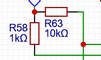
That doesn’t look like a pull-down. At first glance, it looks like GPIO_26 is controlling nOE for channels 1 and 2. I put a LOT of effort into making things ‘look’ right, because then it’s much easier to look at something and see an issue where something hasn’t been connected correctly etc.
I try to never use ‘rails’ for power ports/GND/0V reference ports like that, as well. The point of using the power ports is that they make the schematic easier to read by having less lines crossing places, they have less chance of things getting cross-connected and give you a mental ‘stopping’ point where you don’t have to think beyond that.
I would also always try to avoid current flowing ‘up’, such as where you have the filter caps connected to GND at the top. It makes no difference, technically, but because it looks wrong that’s where my eye is drawn, meaning I’m spending more time figuring out what that piece is using logic and not the ‘pattern recognition’ part of my brain.
I also like to avoid 4-way intersections in wires where possible because it’s hard to tell if that’s deliberate or not. It’s usually easy to avoid them by just moving connections slightly.
1 Like
I agree for sure. There are a few things I would like to shuffle around. I noticed I had a harder time laying things out because the schematic was so different from the real board.
That whole 5V section was irritating because of how I did that. Inputs come in from one side and outputs out the other, That would have helped with my layouts.