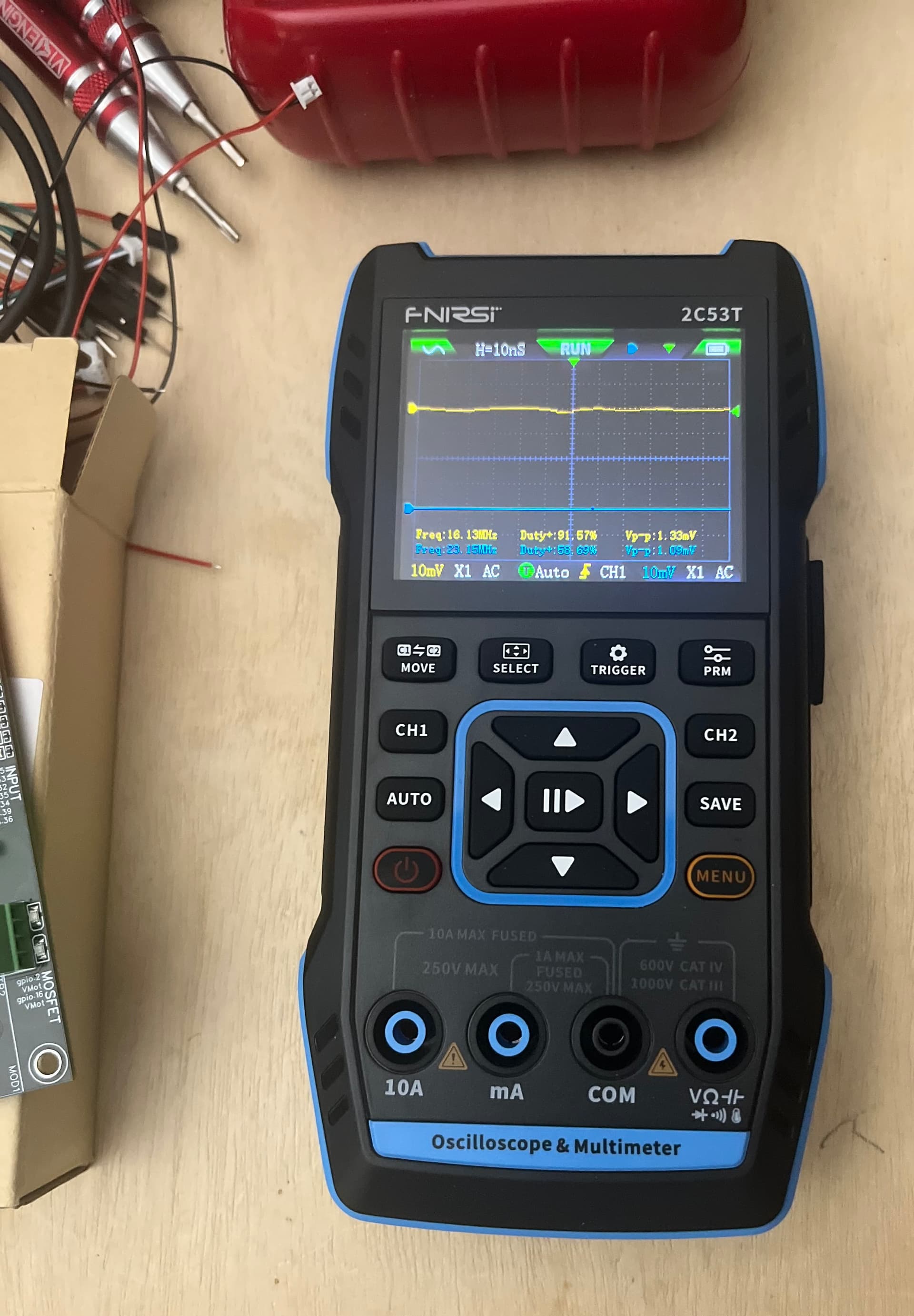
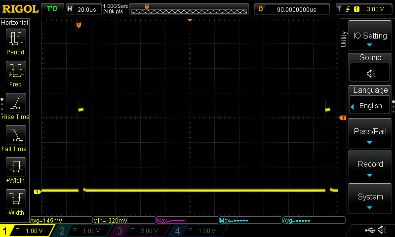
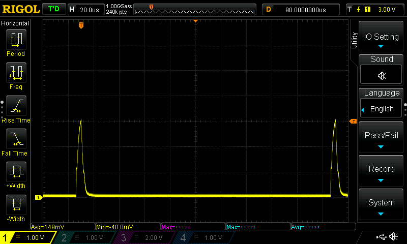
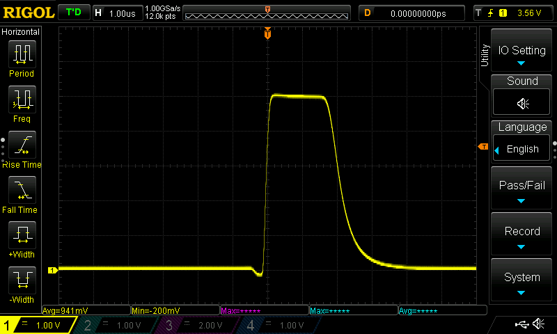
As much as this sucks to have happening on an actual batch of boards. I have never had to really deal with a circuit’s speed much. The learning side of this all is really awesome. I can’t say it enough, thank you guys for learnin’ me.
I will start messing with the values and probes as soon as I find a memory stick to record the screen shots so others can follow along.
i looked at Youtube for how an oscilloscope works and then I looked up the pwm and I followed that alil bit, so I am learnin too!
But i am not going to be making any boards, anytime soon
Easiest way for me to think about it is a multimeter with time as well. Now that I am learning it more, there are plenty of times I could have check some engine sensors if I had a handheld one. It is absolutely fascinating, even more to think my scope is a “slow” one. I have never needed to even come close to maxing it out.
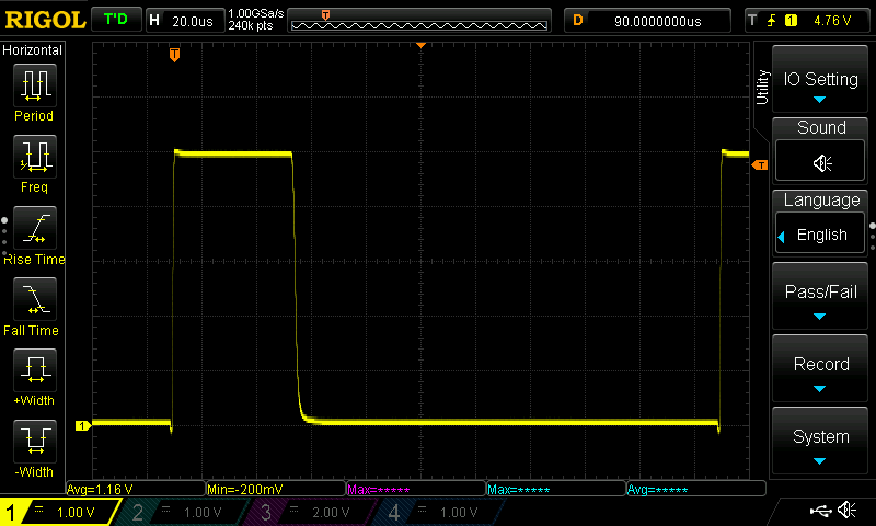
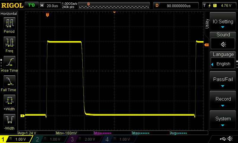
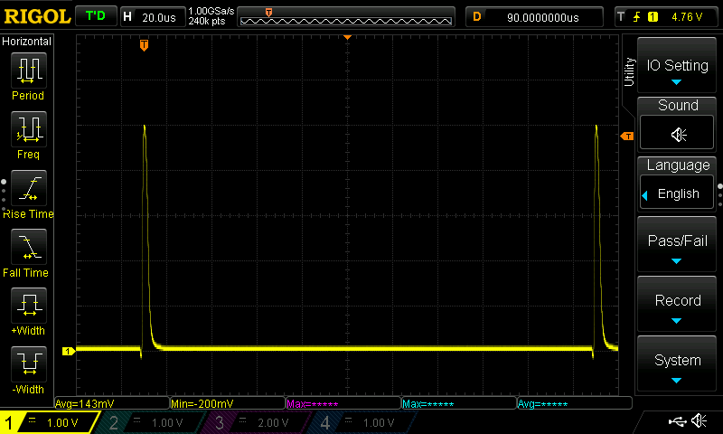
okay half of the previous values did not work. Sorry swapped up the time scale to catch one cycle.
1k and 2.2k, doesn’t come down fast enough.
edit- might have popped that board, bad data
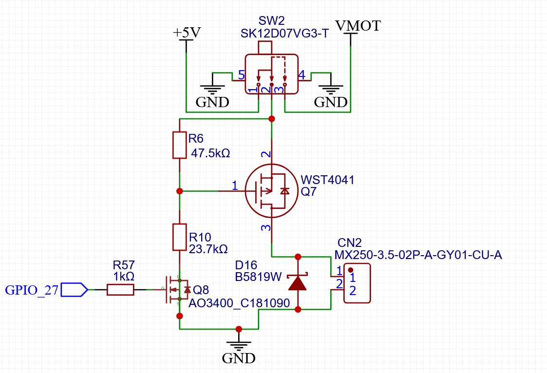
So somehow the answer is with Jono and Jim. They both indicate you need tWo resistors, but I am not fully understanding. Guys Where dies the 2nd resistor go?
well smaller value resistors are helping. Not sure how low I can go.
1.1 and 2.2 get me down to s4
2.2 and 4.4 go to s8
Seems linear but to get down to s1(out of1000) we would need 255 and 510ohm. I am just brute force guessing here. Not sure what the side effects might be. I will give it a shot and let the smart guys look at the data before I do anything else.
Your need is more on the design engineering side than the test engineering side.
It might be a FET part type issue.
This is a signal output, but it’s PWM, so for example documentation about designing fast switching FET circuits is useful. For the laser, you need 5Khz PWM signals, not many hundred Khz swiching like in the buck coverter.
But you’ll find details in the data sheets and application notes. Below is one from Infineon, I bet Jono has better specific guidance and design reference documentation to follow.
Edit- it might also be an argument for having one output that is the Jackpot V1 design and isn’t VMOT/5V switchable. One laser capable output, two generic voltage selectable outputs.
I was seeing Jono’s numbers earlier and wondering if I could swap things out, but I do remember the one component was very hard to find 5v-24v, the other seemed to be specced well. I do need to look again. A lot to learn here. Got a fresh batch of caffeine in me, let’s see if I can figure anything out.