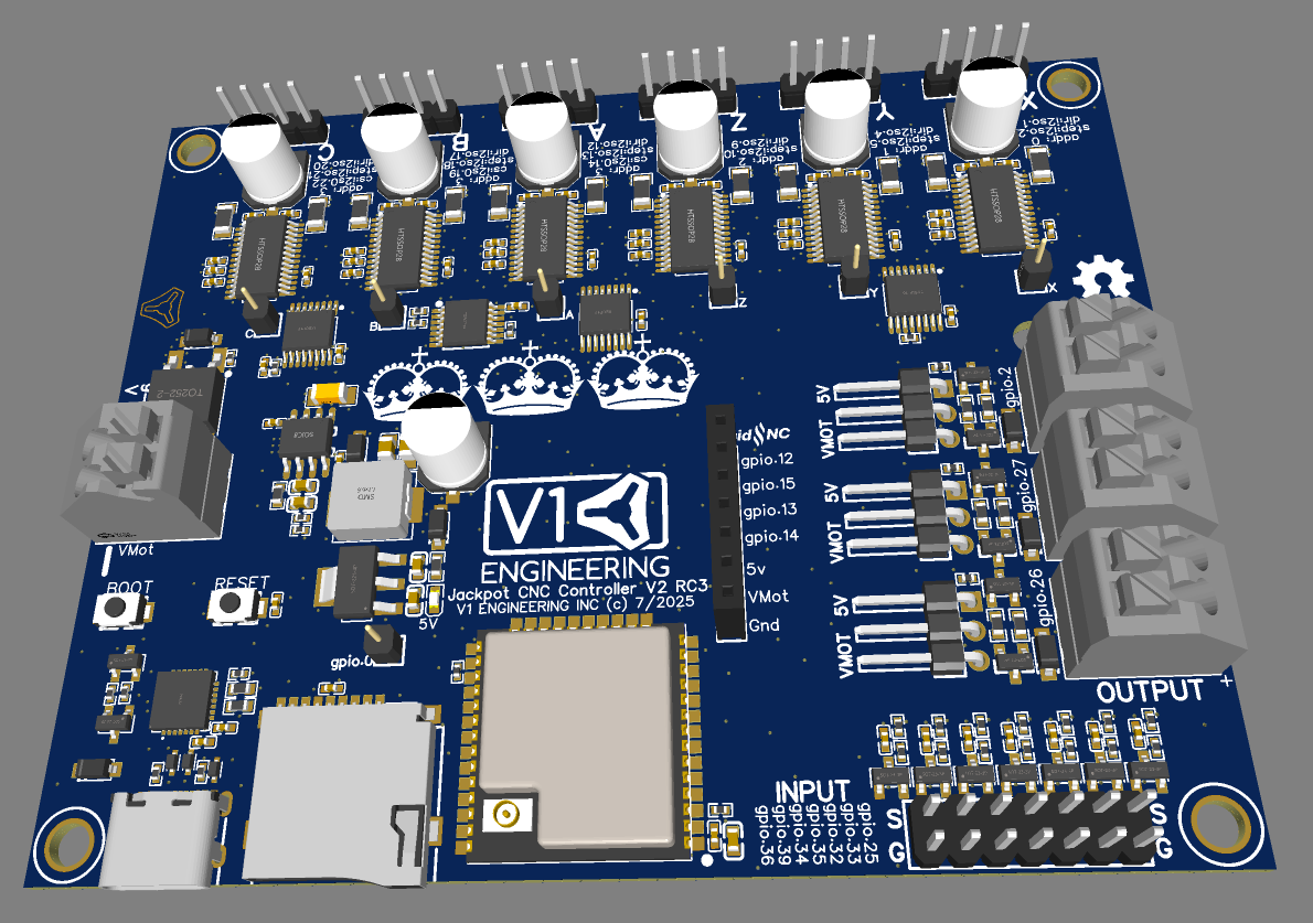
Neat! Looks great to me.
Some minor nit-picks/questions…
-
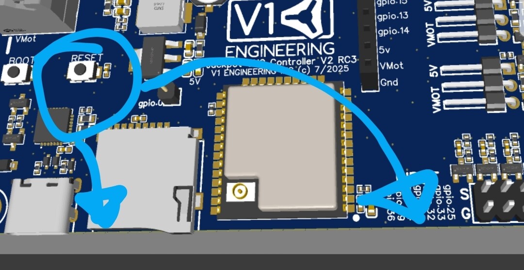
Personally like accessible edge mounted side reset buttons
-
Happy with reliability of these connectors compared to JST based ones on JackPot V1 and SKR?
-
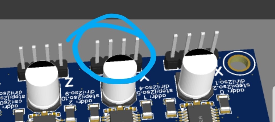
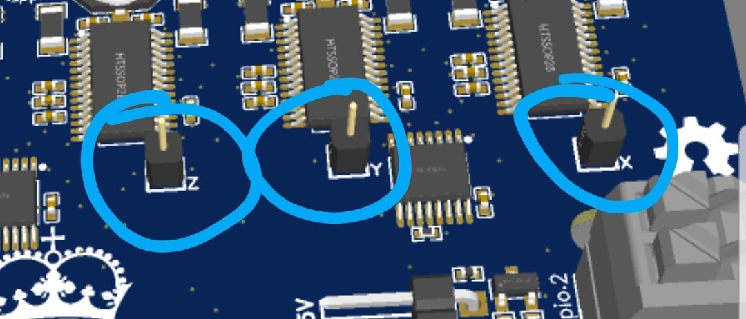
What are these pins for? Would a single block be sturdier, and cheaper (less parts and assembly) ? Maybe leave them off and empty through hole if not required by 95% of Customers?
- Where do I mount fiber optic light tubes to direct light for the UAP beckoningly bright endstop LEDs?
These should only be needed if flashing over USB.
Yeah, that and proper wire management is fine. Otherwise they are easy to swap out for the advanced home gamer. JST requires the entire ecosystem to change including the LRv4 wire channels. I am not changing these.
Not actually there, those are just pinouts for diag pins.
only one power indicator LED, no others.
1 Like
If they’re just test points, perhaps use a Keystone 5000 miniature through-hole test point instead. That’s what we use as our ‘standard’ scope hook test point.
There are also SMT test point options that we use quite frequently although they’re often a bigger footprint than the through-hole ones, they just don’t end up punching holes through your entire stackup.
Alternatively, you should be able to set it so that the part is DNI’d in such a way that the 3D model doesn’t show up.
Assuming any of that’s a problem. I agree with Aza that the single pin looks a little ‘odd’.
Some might actually want to connect them, easy to solder in a jumper wire.
they are not in the build bom but I can not stop them in the 3D model. Also jlcpcb does not allow for bundled items like antenna and jumpers.
been doing some learnin.
Based off what I’ve seen with trying to use the diag pins with Stallguard, I don’t think they’re useful unless there’s a odd use case for sensorless homing.
Sure, I’m suggesting to shift them to something that looks a bit more professional and would actually be used in the context of a test point. Single pins are horrific ![]()
That’s super odd that JLC won’t do that… The offer is still open for me to run it by my CM, if you’d like?
I would love to remove them. I only added them because you were playing with them. If there is no use case just give me a confirmation and I will remove them!
Those were litterally just for Jason. I thought he had a use for them. The idea was he would solder in a wire.
I don;t think I have the funds for a large run. I need a couple small 100 runs first to verify things then after that maybe 200 at a time. Import taxes are really putting a hurting on things.
Understood. My perspective is that seeing a single pin looks odd, it reminds me of 4th year university project type designs or stuff designed to a wicked price point, not a ‘professional’ board, although it’s not a big deal. My thought was that you’ll get the same effect by replacing it with a test point, assuming it’ll never actually be fitted. There may also be parts in the library that are simple mounting holes or through-holes, or you can place a pad directly or manipulate a via to serve that purpose. Anyway, just a thought.
My last run with them was 10 pieces each of a mirrored pair of boards. I don’t think I’ve ever done an order with them bigger than 1K units… Obviously you get it in the neck a bit with the setup costs, but that’s no different to what JLC will be doing behind the scenes, anyway…
Oh, I see now. Just a single surface solder pad. Hopefully removing them is the better move.
Heck yeah, I would love to get more prices.
The hope was that you could use them to tune Stallguard so that you could detect skipped steps and save a job. Basically as a poor man’s closed loop stepper. It works in theory but not practically. It’s highly dependent on feedrate and force so I don’t see it being reliable for that purpose. I’d get rid of them.
Sweet done!
1 Like
Or still a through-hole…
Something like this is what we’d typically use instead of a through-hole pin.
https://www.keyelco.com/product.cfm/Miniature-Style/5000/p/518/id/521/c_id/747/product_id/1309
But SMT test points are a much better approach, anyway, as long as you’re a little careful with them or ‘pin’ them to the board with a via which is still better than a big through-hole but not as good.
Or that, that works too…
1 Like
I just got some of the spring clips for those little boogers. I will keep them in mind. There is another point on the board that will stay for the gpio.0 in case someone wants to use it, I moved away from it to not mess with the boot.
If you want me to check with them on your behalf, do you have a package with the board files, assembly files and BOM? Alternatively I can just forward you their e-mail if you’d rather?
We usually just use regular scope probes with them, although it’s definitely nice having a variety of hooks and clips etc. on hand that work with scopes, multimeters, bench power supplies, signal generators etc. Everything I deal with is low enough frequency, usually, that I just use banana terminals for everything and then if I have to I’ll adapt to the scope/sig gen using a BNC to banana adapter.
Depending on where you got the clips from, be aware that a lot of the cheap ones are fucking terrible. If something isn’t working, double and triple check it’s not the clip. It’s remarkable how garbage they can be.
1 Like
I will send you some files after I make the changes from those pins. That gives me more room for more copper from the drivers so I am moving some traces.
2 Likes
Personally found a use for TMC2209/TMC2226 Diag pins, but that’s for non CNC project. Hoping you end up with a no/low cost through hole, that can soldered/tested.
I will miss the end stop LEDs. Sounds like V1 and V2 will both be stocked by V1E shop for a while anyway?
1 Like
Hmm, I always found endstop LEDs really helpful when troubleshooting, especially when having switched the axis’ by accident. Has happened to me more than once.
1 Like
I just spent the last hour removing them. The pins are pretty easy to get to.
as long as they both sell.
I promise $limits is the better option.
1 Like
I can do it better visually by pressing the endstops and seeing the light. It’s just intuitive. Never ran a single command on my Jackpot. But as long as people are being helped, it’s fine I guess. ![]()
1 Like