Ahhh, and those curves are no good either, got it.
There is always going to be a bit of a curve…but yeah, that is a little too much I think. I need the jp1 as a reference though.
1 Like
jp1 same settings
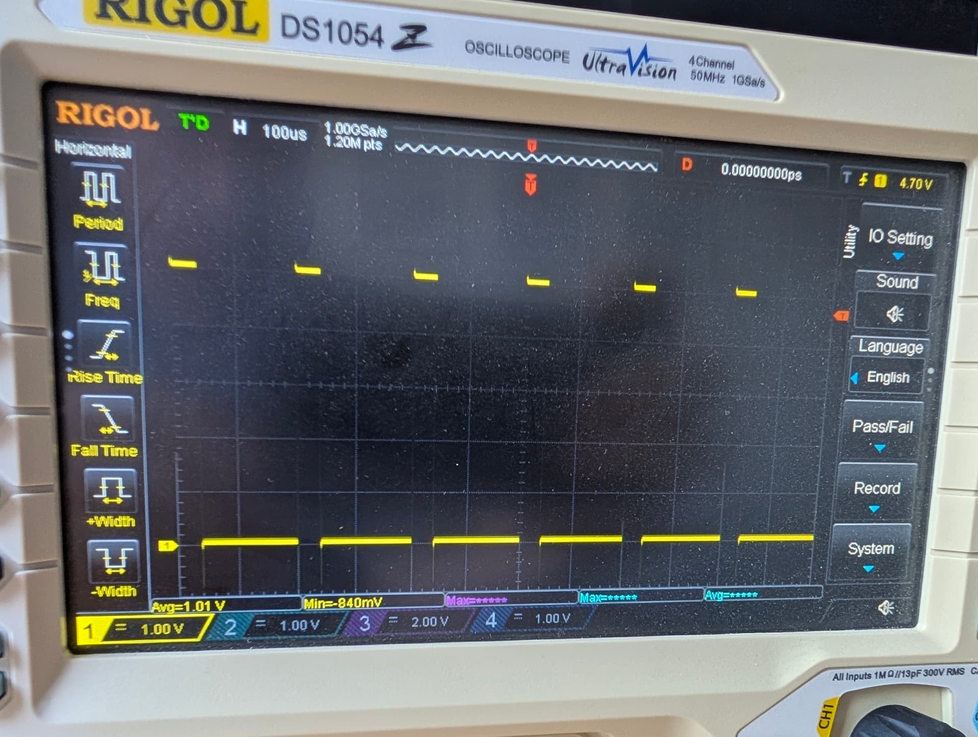
I had to zoom in but s1 even works just fine.
The jp2 is not close. I can try another resistor value, I will try a 1k to see if it improves significantly or at all.
1k is only slightly faster. ![]()
![]()
![]()
So jono said one to ten k on 2 output pins
Ah, yes, when I configured mine on Saturday using the integrated 6 pack board, I used gpio.12:pd.
Yeah I tried a 5k, and a 1k. 1k pulls down faster, but not fast enough.
Do you really need 5kHz for the laser. Many products ship using 2kHz.
I can’t find specs for any diode lasers, or anything else we might use pwm for.
I really hate the new forum editor on mobile.
Half the time I have to reload the pages two or three times before I can select text to quote.
Then , most of the time I cant scroll properly in the exit window. Then I have to rotate my phone for the reply button to appear
Ryan- are you placing a pulldown on gpio 27, and also putting a 1K across the high and low side of the output?
you should be able to turn it off, left top corner of text box
just the output, do I need both? what about the :pd?
crud, I need to head home before I get a cold dinner. I will check back in shortly.
3 Likes
I hear ya, about to drive home myself. I see the email that my Jackpot V2 shipment was delivered a bit ago so I can jump in for a bit in a while.
May be better, we should add to our checks that the outputs arent glitching on boot. That could be bad with many peripherals.
Maybe. It is the tiny icon on the far left that I cant seem to scroll to.
This is why Jonno suggested a parallel 1K resistor across the output leads. You aren’t pulling the output signal low fast enough with the high input impedance of the laser.
For me, as soon as I tried to reply on mobile and start typing, the layout would get messed up and the “Reply” button was no longer visible.
I’m on iOS and had the site saved as a bookmark pinned to my Home screen.
If I open it directly in Chrome it’s fine, but that integrated window the bookmarks open up in, it gets all messed up as soon as I try to type
1 Like
You may need to change the resistors driving that P-channel FET. Stick the scope probes on a bunch of points and see how the signal changes at each point.
I would probe the GPIO pin, the gate of Q7 and the output pin to see. The effective gate drive resistance on Q7 is only 47.5k while it’s turning off (Q8 open circuit, so only R6 is in circuit to change the gate voltage). Q7 looks like it has around 1.1nF of gate capacitance so that 47.5k/1.1nF combo is a 3kHz filter with a 12us step response. On top of that, if you don’t have much current going through it, it’ll need a much lower gate drive (which means a higher gate voltage, in the case of the P-channel FET) to have the drain-source channel resistance increase enough to look like it’s ‘off’.
So yeah, I’d guess if you dropped R6 and R10 by an order of magnitude, you’d see the turn-off edge rate change by a similar order of magnitude.
3 Likes
Okay! That might be getting somewhere, order of magnitude is much better that, a little bit!
1 Like
Isn’t it a similar problem on both sides? Yes, it looks like the Q7 / Q8 combo doesn’t turn off quickly.
But over on the output side, you’ve also got a high input impedance on the laser module, so when you finally switch off Q7, isn’t that then going to have a similar issue with not bleeding fast enough (from the laser input module’s perspective)? Wouldn’t that compound the issue?
Yes, this! Nothing better to see and learn than to put probes around the circuit and see what every component sees as they’re operating.
1 Like
I’m not sure what you mean by ‘on both sides’? The Q8 FET is a bit smaller so has half the gate capacitance and is being driven by a 1k resistor. It will be contributing to some group delay but probably not a whole lot of the actual output speed, given that it’s probably done switching long before Q7 is at Vgs(th).
The Q7 FET is being driven by different impedances between turn-on and turn-off. When Q8 is off, the only thing acting on the gate of Q7 is the 47k resistor. When Q8 is on the equivalent impedance driving the gate is ~16K, so there’s a factor of 3 there, already.
There can also be pretty big differences in how fast a FET turns on and off due to miller current handling, which I suspect might be exacerbating this problem due to the extremely high gate drive impedances.
As for what’s going on over at the laser module, that may be its own entirely different kettle of fish, for sure. I would presume that it’s probably a much higher impedance than we’re talking about here with an added pull-down, even if it has it’s own pull-up or pull-down. But without adding that pull-down then absolutely, it’s likely expecting a logic signal that is low-Z in both states, not a low-Z high state and a high-Z low state. With any amount of filtering on that, you’re immediately reliant on whatever pulling they’re doing to have an unconnected input float to a defined idle state, assuming they’re doing something.
It’s also pretty common for some logic inputs to not like slow edge rates so for all we know it might be unhappy about that, as well, potentially causing multiple edge triggers, etc.