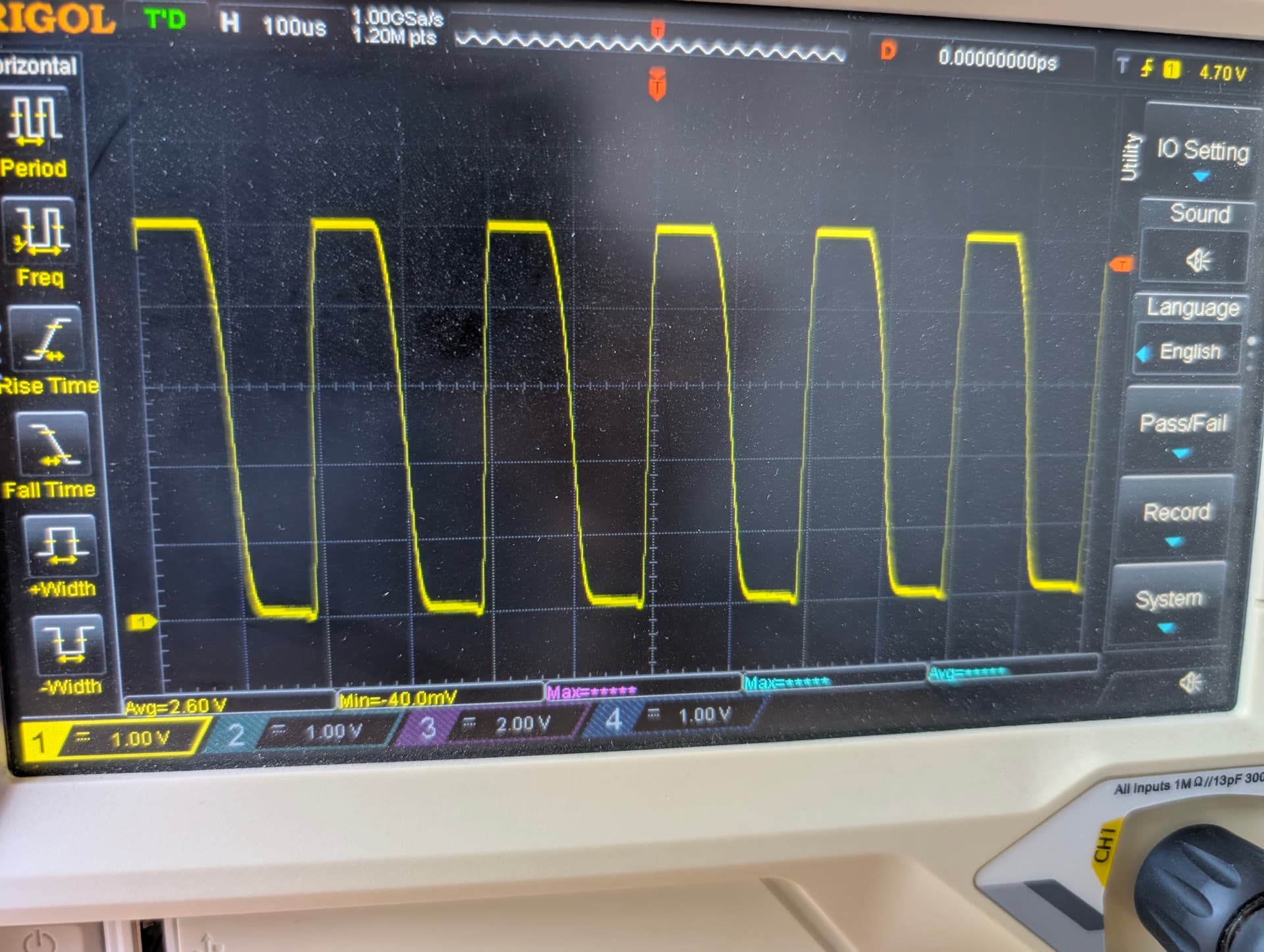
It looks like the peaks are kinda okay but it looks like it is taking too long to fall. M3/4 work as they should
still messing with it.
It looks like the peaks are kinda okay but it looks like it is taking too long to fall. M3/4 work as they should
still messing with it.
The settings all work just fine with the Jackpot version 1.
I am checking some older firmware, it is too far off.
on 3.9.8?
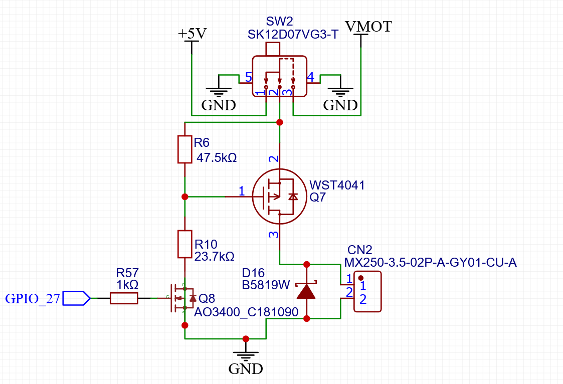
Is there a link to the schematic somewhere? Might be worth checking the filter values and making sure they make sense.
Yes I am.
So wait, if io27 is saying already in use, how can you continue to use it?
It has to be removed from the output section when using a laser;
Right, so that’s only driven high. It’ll need a pull-down added.
You can’t. It goes into an alarm.
So will this work?? limit_neg_pin: gpio.27:low:pd
This was all Google ai, so not sure about it. But below is the reference it gave
gpio.27: Specifies the pin number on the ESP32.
:low: Defines the active state of the input. This is important for telling FluidNC how to interpret the signal.
:pd: Adds the internal pulldown resistor, which pulls the pin to a logical low state (0V) when the input is not active.
The way to think about these things is to evaluate each state it can be in and think about how that will interact with other things.
With the ESP32 outputs, the valid states are input/undefined (high impedance), output low or output high. In this case the high impedance state is difficult because it’s undefined. A FET input should never be left connected to high impedance like that, it can cause all sorts of issues like unknown state or oscillation.
For the other states:
Output low means the Q8 FET is off, the Q7 P-channel FET is 0V Vgs so it’s also off and so the output is nothing more than a reverse biased diode. So overall very high impedance as long as the output voltage remains between 0V and whatever the switch is connected to.
Output high means the Q8 FET is on, the Q7 P-channel FET is -5V or -Vmot Vgs and is on, so there’s a low impedance connection to 5V or Vmot.
That’s great for powering something or for circuits that are designed for that, but for general purpose inputs they usually expect to be either driven low impedance to both logic states or sometimes driven low, and allowed to float high. It’s relatively uncommon to see the other option.
This is why there are so many different ways of handling outputs like that. High current tri-state buffer ICs work pretty well and can drive current at 0V, Vcc or go to high impedance but they’re more parts and somewhat expensive and don’t usually have enough voltage range for what you want to do there.
Open drain outputs are the standard for stuff like that because their 2 states are quite flexible, either low impedance to 0V or very high impedance, essentially open circuit, meaning you can connect a load or pull-up to whatever voltage and it’ll just work. The downside here is that you can only choose 2 states, either very high impedance or somewhat high impedance to a fixed voltage as a pull-up. This means that you also get different edge rates in both transitions so you need to be a little careful with what you hook up to it. Some logic doesn’t like slow transitions from one state to another.
This is the opposite of the open-drain output. Technically it’s still an open-drain output, just with a P-channel FET in the high side so it’s low-Z to the voltage rail or very high impedance. Adding a pull-down will get you a +/- capable output but depending on the resistance of the pull-down you have to choose a tradeoff because for it to change state quickly (low impedance pull-down), you end up wasting current through that pull-down.
In this case, I’d recommend finding a ~1K to 10K resistor and wiring that in parallel with the 2 output pins.
No because that’s referring to the ESP32 pin. This behaviour is caused by the circuit snipped posted by Ryan above. The ESP32 has 3 possible output states while a basic FET output only has 2.
So you can tell me to quit anytime. Gpio 27 used to be exposed/routed for this from the esp, is that pin still available, just under another gpio #
26,27,2 are now the 3 outputs, not broken out anywhere else.
Sorry. I think I just muddied up the water. I will stop
no worries, I am poking around all help makes me look into things.
5.6k helps a ton, still might be too slow.
The part that bugs me is this is a map of 1-1000, this is s200. 600 barely shows any drop and s700 is showing a 100% 5v signal
On the low end, at s50 we just barely get over 3.3v
How is it supposed to work is s50 supposed to be close to 0 and 999 should be 5v
In an ideal world the corner of those square waves in the picture above are 1000 steps apart, 1000 means they touch, 500 means they are off half the time and on half the time. 50 would mean at 5v for just a little blip 1/20th of the width.
I need to see how a jackpot one handles mapping at 1000