Man you are doing god’s work with that much testing.
Sad im already using the expansion module with the relay module on my lr4.
3 Likes
Nothing at all wrong with a jackpot V1, I bet it still sells even with a jackpot V2 released.
As one example of a V1 possible super power…I’ll get back to experimenting with those external stepper adapters at some point.
Also after the V2 is out and stable I’ll play some more with closed loop stepper stuff.
I have a box of external stepper drivers and one axis worth of closed loop stuff.
I also have some testing to do with both versions of Jackpot connected to an Airedale.
Plenty more useful stuff to explore.
4 Likes
I was playing with mine for a bit as well yesterday. This might sound odd but I do prefer the smaller encoders. The large dial is great for large spins but everything seems more geared towards fine movements that feel better on the small knob. Kind of a full hand grip versus a two finger pinch. I was even messing around using it sort of like a mouse scroll wheel, the dial config seems off to me. I will bite my tongue until I use it for a couple jobs, though.
I need to use it more to really try and understand the appeal but so far the software side has been trouble free.
1 Like
The biggest appeal for me, you probably wont ever notice. The computer I do most of my CAM from is downstairs in my basement, the CNC is upstairs in the garage. I can pull up the Webui from down here and upload the file straight to the CNC (no messing with SD cards) then when I get up to the CNC I don’t have to find it from my phone or tablet. I just grab the dial and roll on with it. I always had a problem with the jogging on the touch screens. The dial makes it a LOT easier for me.
So far I have only used an M5 dial. But I did build a CYD pendant. Just waiting for my board for the jackpot to get here. I should have one already but I have looked everywhere and cant find it. Right now my M5 pendant is running on a prototype board from @MakerJim that doesn’t have 5v hooked up on it.
1 Like
There’s another user on Discord with a similar problem starting with 3.9.6. I commented how it was similar to this issue so maybe it will get some attention.
1 Like
I’ll try to get over there in the next day or two and make a comment. I see this as well.
2 Likes
Looks like Bart is out of the country for a couple weeks and cell range for some of it. Mitch might have his hands full.
2 Likes
I bet. I should still get the comment in.
You’re a FluidNC paid supporter and so am I, so I have no worries about me asking for tech resolution for a bug.
1 Like
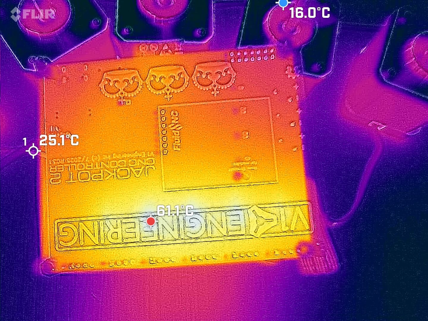
New
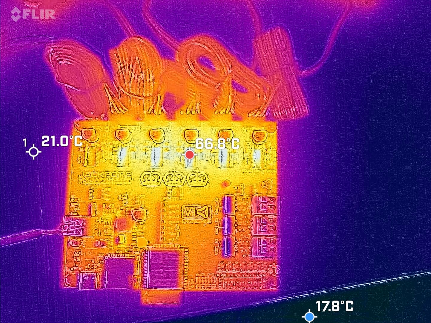
old
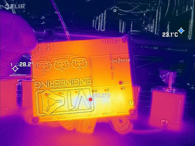
new
Old
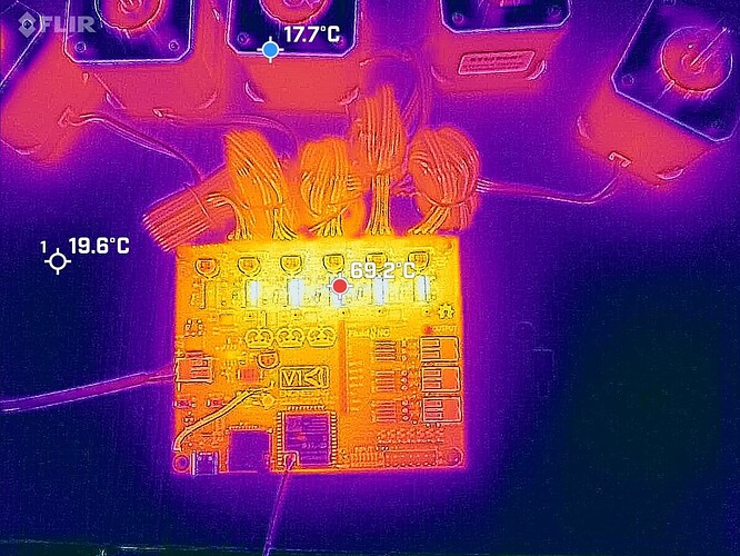
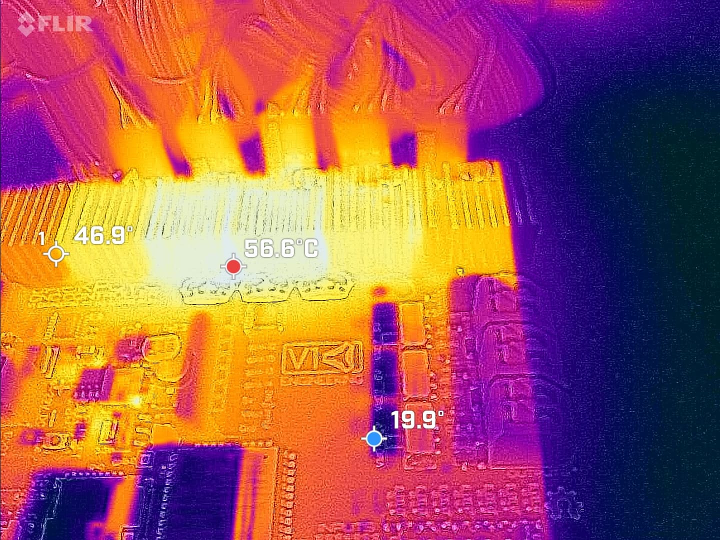
7.1C cooler on the bottom, and 2.4C cooler on the die itself, That is amazing!!! (at least it is to me).
The new one has been heat soaking at least twice as long as well.
7 Likes
Looks pretty good. I will say that 70 C on the board would be beyond what I’d be comfortable with, long term, but it’ll work. I suspect most of these machines will have runtimes in the 10s of hours median, 100s if someone is really keen or doing production work. I’m used to designing for 100k+, so that’s probably fine.
I’m still concerned that you’ll see thermal issues in an enclosure so it’s still well within fan needed territory.
1 Like

I’m very glad. I’ve been sitting here thinking about what other test could be done to verify the thermal margin.
Do you know how the board behaves if a driver overheats? Does FluidNC catch it gracefully? Sticking a small cardboard box over the board and letting it thermally soak is a cheap and easy way to do thermal testing. If it cuts out with the backside of the board at 80C then you know you’ve only got roughly 20C of thermal margin.
That 2nd post with the heat-sinks really does illustrate just how poor the cooling is through the top of the package. All that extra surface area and it’s a 5-6 degrees cooler.
Maybe for interest’s sake you should try the heat-sinks on the bottom of the board.
I still think a gap pad to an aluminium plate as a base for the enclosure is the way I’d go, it’s just so alluring to have an option that isn’t blowing air and potentially chips onto the board, especially onto the populated side.
1 Like
It’s just expensive. These heatsinks are commodity and cheap. Custom aluminum and custom placement of thermal compound/tape is in this case astronomical. That is a mod for users.
We have to remember, currently these boards, all boards are now at least 55% more cost. Adding a dollar here and there on top of an extra 55% is going to be brutal for sales. I am honestly wondering if sales will stop. The boards need to be priced at about $87 now to keep my same margin. That margin technically needs to increase to account for any dead boards that will now cost more.
The whole exercise was to try and reduce cost because of the tariffs, and make a few improvements. With the added reverse current protection, and 6th populated drivers we are now at nearly the same price, the added rj socket is going to take the cost above the V1.
1 Like
Indeed. Note that I said that this was the “way I’d go”. Also notable is that this is something that can be done with machined flat aluminium plate. Not really a huge stretch to the end user when you’re making a machine that, you know, machines things.
Keep that in mind with ordering through JLC. I don’t get ‘dead boards’. Ever.
Absolutely, there is a very difficult job involved in all of this called product management. It’s often as much of a job to define what the product should be and to keep it on track and meeting those goals as it is to design the thing in the first place. I would expect that you’re never going to get people here doing that job for you, that one is entirely on you.
1 Like
![]() Good test project for aluminum!
Good test project for aluminum!
I have had a batch with funky diodes but I replaced them, and honestly I might have just selected a poorly specced replacement.
We are in an odd place right now. I love the jackpot but in all honesty if we can get another board for less, I will do it. Hard to imagine anything else beating this price but we have to wait and see while these new costs start to trickle in. I should be importing at the wholesale rate, where an end user is importing at a retail price. With de-minimus gone for the US I should have a slight upper hand but, not always.
2 Likes
Heck yes!
People will discover that they can buy a crappy MKS TinyBee on Amazon for $38 and expect that somehow that’s just as good. When it isn’t, that’s not on you, Ryan. It’s on them.
I’d even call that out in the docs where the supported board types are [whatever], and other stuff is on the user to figure out when they build it.
Want it to work right? Buy a good board. Even if you consider your time free, it’s still a win in the end to use the right controller.
I’ve been saying for a while now the Jackpot is worth at least $100. It’s been a huge bargain where you kept the price super low.
3 Likes
When the inventory sells through, I am sure that will go up in price as well. Using the pots is the biggest drawback if I remember right.
$35 for the tiny + $27 for drivers, $62, jackpot at $65 was an easy choice, not at $85.
With all that said, users outside the US are going to still enjoy the great prices and the new board. Still a clear winner for the international crowd from elecrow.
1 Like
Two pin version? PSM712-ES | Datasheet | ElecSuper | LCSC Electronics
Since the rj12 only uses two data pins just protect them, or is there a reason to do all 4 of our pins? I feel like the other modules are more safe.
Unsure of this part. On both the 5v and 24v, not seeing anything on how to size them?
1 Like
Why do you think that?
Buying the officially supported board and getting really good community support has to be worth more than $20.
I’m super appreciative of how hard you work to keep the entry costs low for a V1 machine but it also has to be worthwhile to you for all that hassle and frustration.
3 Likes
That’s a TVS based design intended for RS-485 which is a differential bus that can sit significantly above or below the voltage of the receiver’s 0V rail and still work. With 1mA through it, which is where it’s only just starting to work, the voltage will be 16.3V typically in the +V direction or -9.8V in the -V direction. With actual current going through it’s specced at 24V/-18V…
That’s likely fine for an RS485 transceiver, although most of those have decent ESD protection built into them so if I was adding extra protection I’d want it to handle a bit more than just a modest ESD strike.
So in the situation where we’re trying to protect a 0V to 3.3V GPIO pin, I’d say that will do utterly nothing. By the time the ESP32 has 6-7V on its pins in the +V direction or maybe -1V in the negative direction it will be in full breakdown/conduction mode, so even during an ESD strike it’s relatively unlikely that the ESD suppressor will do anything at all because the ESP32 has already absorbed all of the energy, likely damaging it in the process.
The reason to choose the thing I linked above is that it’s a diode bridge style ESD supressor. Instead of trying to absorb the energy with TVS diodes it directs it to the rails, a TVS or ‘short circuits’ it through the diodes, depending on the direction. Absorbing energy with a TVS always kinda sucks because you have to size the TVS relative to the strike you’re expecting and how much voltage rise you allow. If you want a lot of protection or have tight voltage tolerances then you need a big TVS. Big TVSs have lots of capacitance so you end up loading your high speed lines and ruining your signal integrity. The diode ones don’t do that because they’re just diodes so you don’t get the effect of a capacitor on the line meaning they can have a bigger TVS for the same level of protection. They do have some side effects like potentially lifting the supply voltage if there’s a lot of energy to be dissipated or a different fault occurs like incorrect wiring or a short etc.
As for 2 lines vs 4, I’ve just used the 4 line one before because that’s what I specced. I don’t know if there is a 2 line one. For 2 lines I just parallel 2 of the channels which essentially gives you a bit more current handling/redundancy, but really it’s just to lower unique BOM items.
It’s worth noting that this is why I always try my best to never expose GPIO pins to the wider world and would always use something like an RS485 transceiver where possible. The ‘proper’ way to do it would be an RS485 transceiver at each end and then the bit that’s most likely to have destructive events occurring on it is differential, has higher voltage thresholds and is just generally much more robust.
1 Like