I have to have this conversation with my wife a lot…
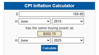
We just had to buy a car for my son… $10k ain’t what it used to be…
I have to have this conversation with my wife a lot…
We just had to buy a car for my son… $10k ain’t what it used to be…
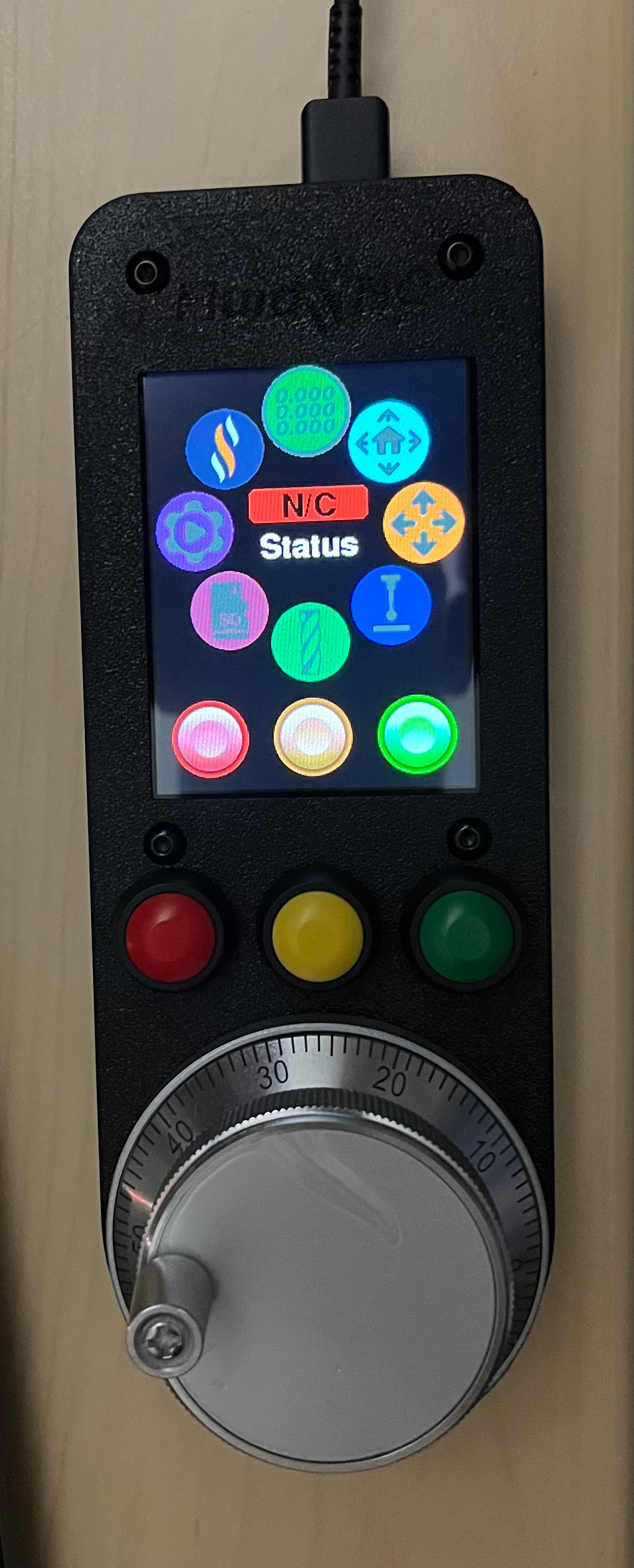
I have all the parts here. I actually like the smaller dial. The big one is sexy but I don’t think it is very ergonomic. Can’t wait to build one.
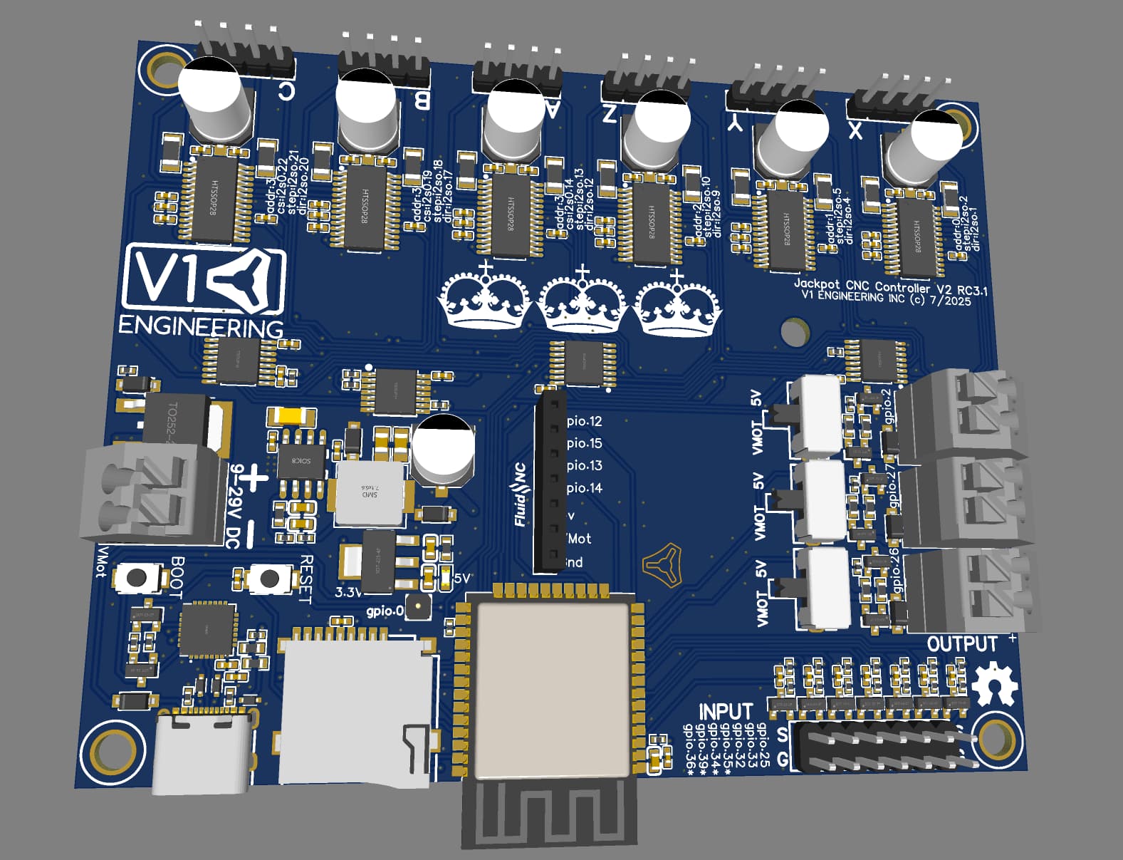
Wondering what it takes to make a new pcb with all the stuff in one package.
Thank you, I am almost done rerouting the uart stuff. Everything on the board has moved except the input pins…lots of work. Then I will see what I can do about the extra spot.
We only have to protect 4 pins, that looks perfect. Two components, I love that.
I am thinking more along the lines of, by all of Bart’s stuff separately from all over the place for the DIY. This avenue will work as is with both boards already.
Or I would make a full “kit”, as in jackpot connection, wire, all the pendant parts (maybe pre assembled in an injection molded shell). DIY is good but now that is getting expensive shipping multiple packages, we have to start thinking a bit different crossing boarders.
My thoughts exactly.
I have all the parts for my CYD pendant, just have to build the wire harness and re-print the enclosure as the A5M is misbehaving on me. I’ll be testing this on the JackpotV2 on the JL1 plus with the M5Stack also. It’ll be this week sometime.
The nice thing about this approach is that if you have the same IO voltage as your supply then the array protects both lines and the supply rail somewhat. In this case I would probably use the 3.3V part and either route it to the 3.3V rail or leave it disconnected without any capacitor on the Vcc pin if there’s no 3.3V rail available. The capacitor on the pin adds some extra capability in terms of handling the strike energy but without a supply rail will need to be charged by the GPIO which can work in some cases and cause signal issues in others.
Alternatively, you can use a 5V part and connect it to the 5V rail but you’ll get coarser protection with a higher voltage rise on the pins under a fault condition but with the ability to handle a much more significant ESD/surge event.
Yeah, this seems like a really nice avenue for a premium option. I’ve been thinking about it a bit more and I really like the idea of the dial with the logo on it, assuming it’s not insanely expensive. It’s something that’s a neat customisation touch and stands out as a clear difference. I think people are happy to pay a premium when they feel they’re getting something for that, but it’s difficult to convince the average user to pay the premium if it’s just better supply chain management, testing or QA when the end product looks/performs identical. Different colours or a logo to show you’ve gotten the ‘proper’ one is a big draw card.
The basics are almost all there. Need to figure out if we add the holes near header, or just use the plug in module. Not sure many people will be able to buy a single jack and solder it in for less than paying $8 for one with protection already.
That’s fair.
Looks great. Isn’t your brand color red? Can we afford red? haha
He just changed it.
Something something eventual consistency
I was just about to say. New picture. I was so confused. I see the new one everywhere. Probably just need to refresh.

Yeah I just saw that in the other thread ![]()
Odd that it changed it for the reply but not for his actual post. Must just not have finished updating yet
Anyways… Back to regular scheduled programing…
New Jackpot. New Ryan
They changed something in the matrix- and just ate my last post too.
Re-creating.
Are you planning or at least seriously considering a V1 sourced pendant kit? If so, just make the module be the standard option.
Have you tested the TMC driver thermals further? I’m not convinced these shouldn’t at least have the heat sinks in the shipment with the board.
Did you report the weird endstop behavior on FluidNC versions > 3.9.5 in a GitHub ticket?
Have you tested those new switches for output voltage source to confirm they are reliably break-before-make? Don’t want to be able to short the two power rails…
He did a couple days ago but no response yet.
He’s really finally been replaced by Fred Durst… ![]()
Yes, I think I will be giving it a serious look. I have been wanting to try out a recommended injection molding company, very inexpensive molds and the per piece price is obviously hard to beat. Just need to spend time on the actual hardware.
I would really really prefer a wireless option but it will not cost much for a 100-200 unit trial run.
I already have a few hundred heatsinks here now, but I have made significant changes to the thermals on this new board, as good as I can get it without just making it larger. I think.
With that said, the TMC power input and stepper output are specced to pretty much max current with the trace width for a 10C rise. I know we never get anywhere near a sustained max output but that seems like a good enough second reason to go up to the thicker copper as well, first being heat transfer. I will check the prices on the next round.
My whole idea being try to get our standard YBR use case to be completely fine without heat sinks, and if you want to crank it up you can add heatsinks.
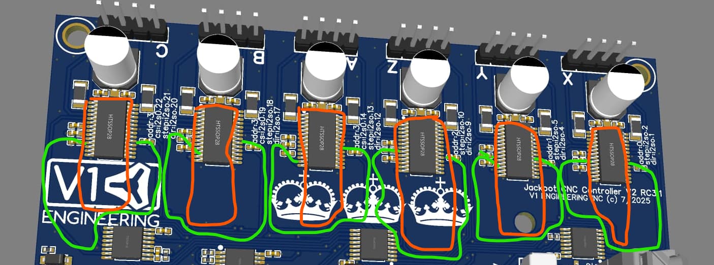
I’m sorting through my messy home office / home lab looking for what I did with the IR camera. It’s a cheap attach-to-phone unit, but I’ll see if I can get something better than anecdotal or finger-tap testing on the JL1. It didn’t get warm sitting with the two stepper drivers on with holding torque for a day and a half, but that’s a terrible test.
With the boards we have, no real extra heatsink transfer accounted for, on a 1/4" standoff I already got the 10C difference at a setting of 900(and we only use 800 usually). I am beyond curious to see if all the extra work pays off in a temp difference. Spreading those drivers out a little bit was a crazy amount of work, I will be pretty bummed if we do not at least drop another 3 degrees. Hoping for over 5C though.
wait what holding torque, 500 or 700?
I did my test with a moving and hold set to 900, and tried both ways. I think the boards hit within 1 degree of the final temps after about 15 minutes, but I will try to keep better track next time. I let them run for several hours, when the readings stopped going up, I waited another hour and I called it.
Ooh good question- Looking over the JL1 config, it didn’s specify a holding current- it predates the newer changes. I need to roll that into my new config.
I finally was able to complete some 0-10V spindle testing on a Jackpot V1, so now I’m going to do Jackpot V2 expansion module testing and hopefully starting later tomorrow some thermal tests.
I loaded firmware on my first CYD build, still need to wire it up and re-print the lower housing.
The JL1 wont stress the new Jackpot, its current is only 400mA to the steppers.
Maybe back to the MPR&P for the next test board.