Ribbon cable will hinder length. Right now my pendant stays at the end of the table (X0Y0) but can easily be moved around with me anywhere the CNC can go. That seems like it would be a lot harder with a ribbon cable. I am fine either using barts board or building a dupont end for it if need be. Not a big fan of the ribbon cables personally.
airedale uses 5 pins, not 4
Edit: V1 stepper extensions are 4+2. Maybe that’s OK. Let me think about it.
in that case buy Bart’s $25 kit
either option would still use RJ12 curly cable to pendant.
except with no ESD protection on jackpot, maybe that’s OK with an Airedale in, and fine with an expansion board in the expansion connector like Bart’s.
Edit2: Ryan what’s the current contact count on the latest RC Jackpot V2 expansion connector? 7 contacts?
OK, I already have extra V1 stepper extender cables. Wednesday PM or Thursday AM I’m going to rework my 2nd RC jackpot board to change out some resistors, then I’ll test using a V1 stepper extension cable to connect a Jackpot to my Airedale board.
Noodling on it, I’m thinking of using the 2-pin end to connect GND and VMOT, and then the 4 pin end for the rest of the signals. On the Airedale side, it looks like there’s just barely enough room to install this with the last wire of the 4-pin connector hanging unused off the end of the header on the airedale.
You know it is killing me that the pendants cost more than the control board. I really want to target those next so I am trying to be proactive in this new design if need be.
Oh I forgot to include the $27 I spent on the FluidDial Connection Starter Kit. If we could have native connector for a pendant right on the board that would be sweet.
I need to look at what protections are on the rj12 module. If we can use components already in the bom it is a no-brainer. Have to make sure they do not interfere with any other modules though.
The CYD is much cheaper than the M5Dial.
The capacitive CYD is $21 and the Dial is $17 on Amazon. I’m sure if you made a bulk order somewhere you could get them cheaper.
The pendant expansion module by itself is available on elecrow for $8.
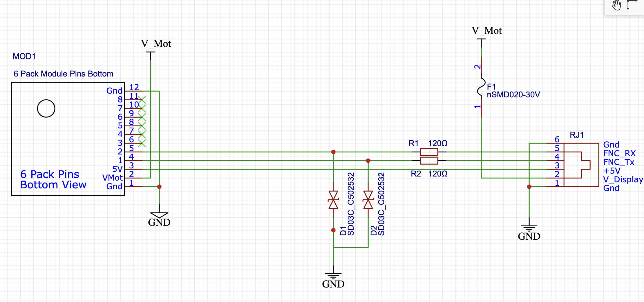
Mitch used a pair of SD03C_C502532 (LCSC C502532) plus a pair of 120 ohm series protection resistors. The diodes for ESD, the resistors for current limiting. Schematic below.
This warrants a check in from @jono035 , this isn’t likely the ideal protection for the IO. It does seem to be effective for Mitch and Bart to drastically reduce blown ESP-32s.
This further cements two options for us:
A user wanting only the pendant can get the $8 module, plug it into the jackpot (v1 or V2) expansion header then use the standared curly RJ2 cable to connect to a pendant.
A user wanting the Airedale could use a cable to tie a Jackpot expansion header (either V1 or V2) over to the Airedale input connector. They also use the curly RJ12 cable from the Airedale to the pendant.
For us, though, the question is do we want to still keep the series current protection and ESD mitigations? Probably.
Note: EDITED. VMOT is available in either scenario, the expansion board adds a fuse for VMOT
What are those going to, just plain GPIO pins? It’s likely fine but I’d guess that the 120R series resistance is doing most of the work there. I’m never a huge fan of using bidirectional TVSs like that, nor of keeping the TVSs on the microcontroller side of any shunt impedance.
ESD strikes can be either polarity so a negative voltage strike relative to 0V will see -4V on the TVS before it starts to conduct, which means the entire burden of that strike is likely in the parasitic diodes or ESD diodes of the ESP32 itself.
It’s not ‘bad’, as such, it just gets a little weird. ESD can and will hurt SMT passives, just usually less so than semiconductors. A big strike could easily take those 120R resistors and increase their impedance by damaging the film.
I also typically think of TVSs on lines like that as a bit of a brute force ‘coarse’ protection. I’d put them directly on the ‘world’ side of the circuit, then put the series impedance, then go to a shunt impedance as some kind of filter for any input line. Given the short-term and relatively low total energy of an ESD strike, a filter actually works marvelously to limit the overall voltage seen by GPIO pins. A TVS will absorb the majority of the energy and ‘clamp’ the impulse in the 7-10V range while the filter then takes that impulse and flattens it out to only a volt or two. That’s not as effective for fast circuits where you can’t filter them as much but it works great for slow GPIO. It’s also less effective for surges than it is for ESD but still.
The ‘gold standard’ for ESD suppression in my opinion is to use a dedicated ESD array that connects to +V, 0V and the lines. It’s way more effective to shunt the ESD strike current to a voltage rail and large capacitor than it is to try dissipate it in a TVS, then a TVS can be used to keep the voltage rail from running away on you. That option is also usually MUCH lower capacitance than an equivalently sized TVS so is more appropriate for digital signals, although that’s more of a USB/Ethernet scale consideration or fast CAN etc. but would still be applicable to a high baud rate UART due to the lack of configurability in terms of when line states are sampled etc.
In the past I’ve used something like a Littelfuse SP3002. They’re a nice part to use because they have 4 IO pins but you can just parallel up any that you’re not using, so they’re a nice layout with 2 lines because you can just route straight through them and potentially not even mess up the impedance of a balanced pair, even. I would always include a good quality decoupling cap right at the VCC/0V terminals, too. https://www.littelfuse.com/assetdocs/tvs-diode-array-spa-sp3002-datasheet?assetguid=c8b2f2f8-79d8-4a9c-8435-7393b0361abe
Both sides it goes ultimately to an ESP-32. In the Jackpot and in the pendant those are UARTs TX/RX pins. (yes, I find it ironic that the pendant has every bit as much compute power as the jackpot host. Maybe more humorous than ironic. )
I agree if using a TVS it should be on the world side downstream of the series protection resistors.
The littlefuse part is nice. It’s half the cost of the TVS. 53 cents for the littlefuse and 42 cents each for the two TVS.
Anything we think a user might regularly connect or disconnect we should have some kind of protection for.
Maybe the best option on further reflection would be for Ryan to carry or make the expansion board himself and tell either pendant users or Airedale expansion users to always get the expansion board.
I’m also not completely sure that the fuse for Vmot is necessary given that we’re usually using current limited supplies anyway… That appears to be a 200mA Ih polyfuse. At 2A it’ll take ~100ms to trip which is plenty of time to have browned out the supply and reset things anyway.
I really like the idea of including fusing, especially resettable ones, but it’s SO difficult to do in a way that actually protects anything at that scale, I mostly end up not bothering. If I decide I do need current protection then these days I’ll do it with something active because you get other capabilities like the ability to do high-side switching, adjustable current limit vs time and potentially current draw feedback.
Having the phone cable compatible with the existing pendant is a big feature. But think about why. It is because it is a standard and you can connect a pendant without getting out the soldering iron or wire strippers. This is a premium feature for people who just want to plug it in and have it work.
If you make your own pendant. Go for it. But make it compatible with the existing plug. If you are putting one connector unpopulated on the bottom of the board, make it the dupont. Anyone running the dupont is going to be willing to solder already. Someone could also make a daughter board for the RJ cable to get dupont from the phone connector.
This feature changes the “marketing” or “style” or maybe even the target audience for the board. It is a killer convenience for someone with the money. It also nullifies one reason to go to a different board with the expansion socket. Don’t do it just because it is a grab bag of features. Do it if it fits with the board you’re trying to make.
Honestly, I think it is a great fit with the other changes you’re making. Like integrating the drivers and esp. this makes the board fit better into one solution for most people.
The negatives are that plugging in a macro switch for a conference means a little more thought.
It would be a gold deluxe premium feature to be able to buy a V1 package that had a motion controller, pre-installed daughterboard, pre-flashed pendant, and cable all in the box. Hook up power, plug in steppers and endstops, turn it on.
Say $150. Can you make reasonable returns at that price point? What about $200?
This takes nothing away from build-your-own. I build my own because I like building things. But then again I do too much building machines and too little building cool stuff with those machines. Even for me, there are times when the half week of mucking around is a major annoyance compared to buy and use immediately.
I don’t want to derail the convo too much. But the latest controllers on the nintendo switch 2 are $85/$95. Inflation is real and we can’t keep thinking of prices the way they were in 2015.
I am all for having the price point within striking distance for someone who has very limited funds. But also, there are a lot of people that paid $150+ to go to open sauce and next years tickets are 20% higher.