More progress!
Endstops are installed, connected and tested. They work!
Now I just need to square it up.
More progress!
Endstops are installed, connected and tested. They work!
Now I just need to square it up.
So I am planning to re-square the cnc this weekend.
But I’m needing help with the whole auto squaring / auto level stuff. And I apologize because I feel like I need yall to hold my hand on this one.
M666 is the code for it, but how is it used?
Where do I enter the code? - post processor or on the fluidnc screen?
How do I set it to automatically auto square / auto level each time?
where do I enter to made adjustments if it is out of square?
I’m sure it will be pretty simple, once its explained, but just lost on this one.
I swear, every time I see that M-code, I feel like this needs to be added to the bottom of every spoilboard, just in case…
Shoot sorry I need to get on this one …The jackport does not use M666. For that one look at the config settings in the webUI, change the pulloff amount for either side of your machine (easier than before) than use the Save button I made on the homescreen.
I’m not connected at the moment.
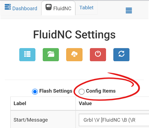
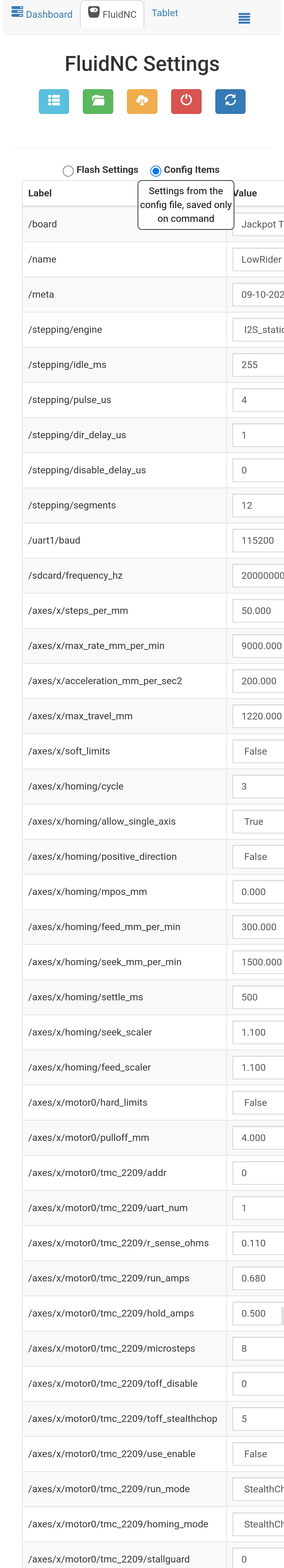
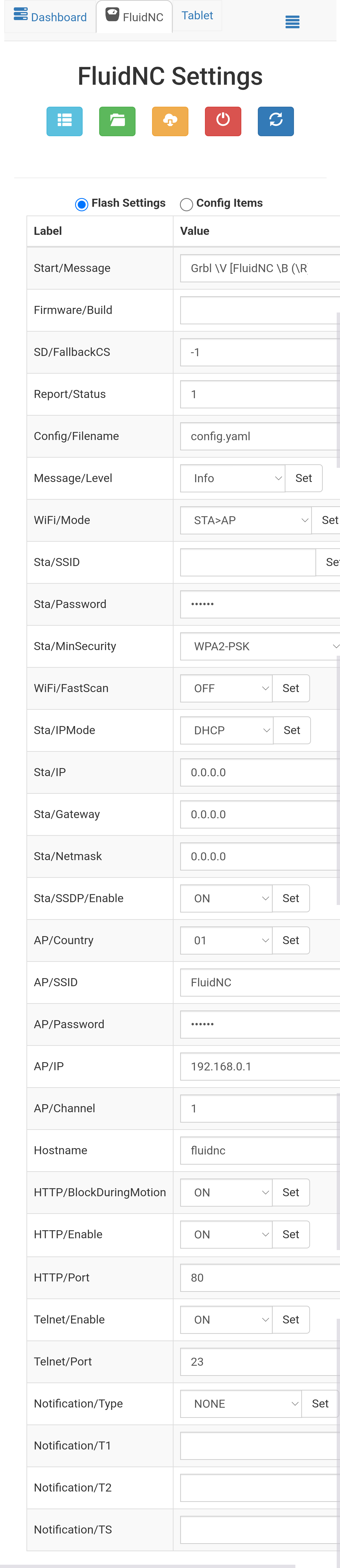
is it under the Fluidnc tab - config items?
or one of these?
I took these screenshots the other day but did not grab one for the config items.
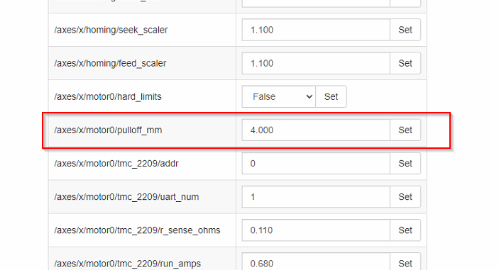
Correct. It will be under the “Config Items” tab, and you will find a pulloff_mm setting for each motor
so you should have all of the following to be able to edit:
/axes/x/motor0/pulloff_mm
/axes/y/motor0/pulloff_mm
/axes/y/motor1/pulloff_mm
/axes/z/motor0/pulloff_mm
/axes/z/motor1/pulloff_mm
Perfect. thanks. I knew it had to be fairly simple.
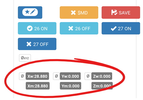
I assume the Y0 Y1 Z0 and Z1 are equal to Y1 Y2 and Z1 Z2 respectively on the jackpot diagram below?
X is pretty obvious.
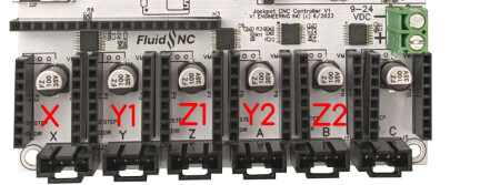
That is correct. Also add about .2mm to whatever adjustment you find needed.
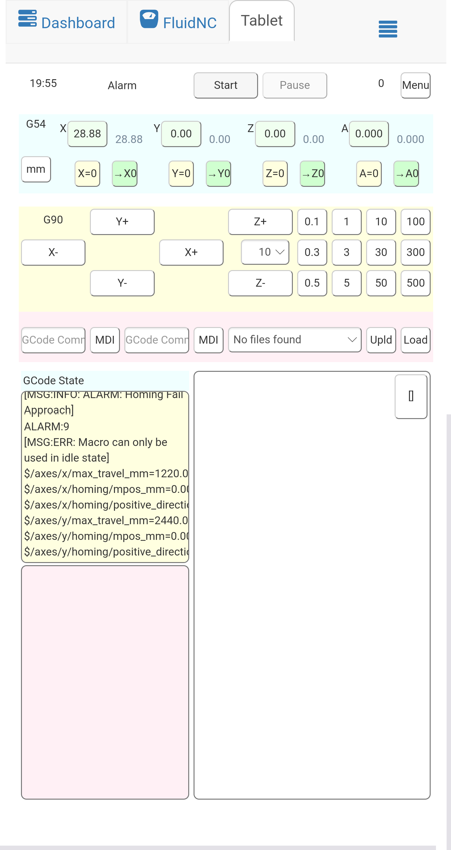
AAAAAGGGGGGHHHHH I hate big thumbs and little screens!!!
the number of times I hit the 100mm jog button instead of the 10mm jog button,
Thank for cofirming @Jonathjon Why add .2mm to the amount needed to adjust for square?
At any rate, I’m 1mm off from square.
I believe @SupraGuy , you had a solidowrks set up to calculate exactly how much to adjust for?
@vicious1 can explain it way better than i can. Something about the starts aligning and solar flares.
Just kidding. Its to do with the location of the marks vs the location of the endstops. the endstops are wider than you can mark with the machine. apparently it takes trigonometry to get it dead on but for the most part the additional .2mm gets it real dang close.
Hopefully I got that explanation corret Ryan!
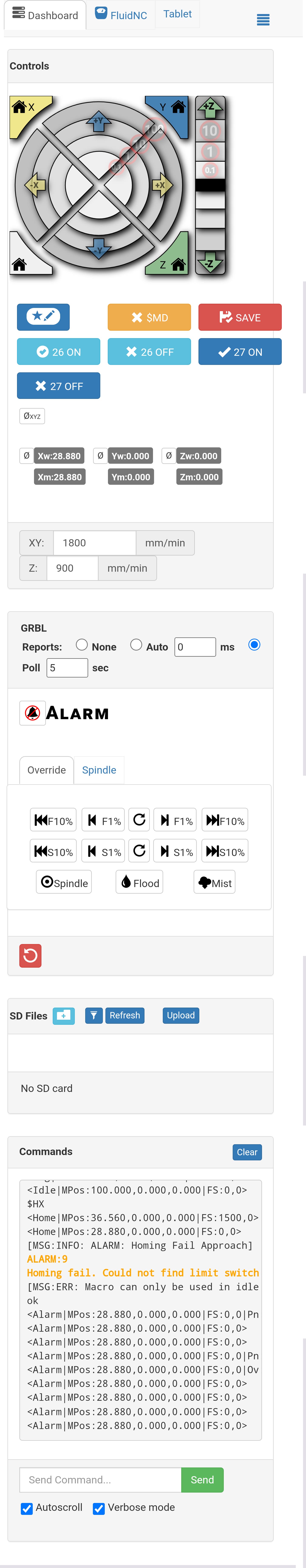
Zoom in on the controls.
Same problem. Broke a BRAND NEW V1 1/16" endmill once by hitting the wrong button. Now any time i use the buttons to jog i zoom in as far as i can. Seems to help a lot!
I’m going to use your screenshots if you both don’t mind in the DOCs.
absolutely go ahead. When I change the config settings I will try and remember to get a screen shot of that as well.
Yeah, I forget you can do that.
I don’t remember if I did it in FreeCad or fusion.
Basically, draw an almost horizontal line segment the length between your belts.
Then draw another line segment, and constrain it to be parallel. This is an arbitrary length. Say 300mm. Join this to the base line with 2 lines constrained to vertical of 300mm. Dimension the 2 points diagonally opposite (should be near, but not exactly sqrt(2)×300 mm) change those dimensions to be your measured diagonals. You can change the measurements of the line segments to match an actual part, of course.
Now take dimensions of the first line segment to the ordinal axis. The difference between the 2 is the amount to adjust your Y end stop positions by.
I did this with a larger square, but in hindsight, using something smaller that I could measure more precisely with calipers might have been better, since I had to guess at partial milimeter values. Of course my sketch is pretty easy to manipulate, so I could probably manage something my 180mm calipers can swallow. Significant digits is kind of what matters here, so something over 100mm with 2 decimal precision is better than something under 1000mm with no precision decimals. I know I have the sketch somewhere…
Ah. There it is.
@SupraGuy Yes, that’s it. Thank you
thanks. I’ll get that worked out in the morning.
Finally had a chance to start dialing the in the squareness.
1118.25mm x 1118.75mm on the diagonals so far. I should be able to get it closer to indistinguishable when measuring. A flat measuring tape helps a lot!
For level, what is the best way to measure? can the probe be used somehow? or measure the height from an endmill to the table?
That is better than I would shoot for!!
Yes you can probe each side and read the current location, then take the difference.
Wow, that sounds like my mother in law when she is sleeping, BAHAHAHAHA!