I came up with this, and thought that it might help someone avoid re-iterating my experience of making dozens of squares chasing down how far to adjust the endstops from triggered on a LowRider3.
The idea is that measuring the diagonals for the corners tells you how close to square you are. but not necessarily how much you need to adjust to FIX it. As a result, I did this many times with trial and error and still didn’t get the results that I wanted.
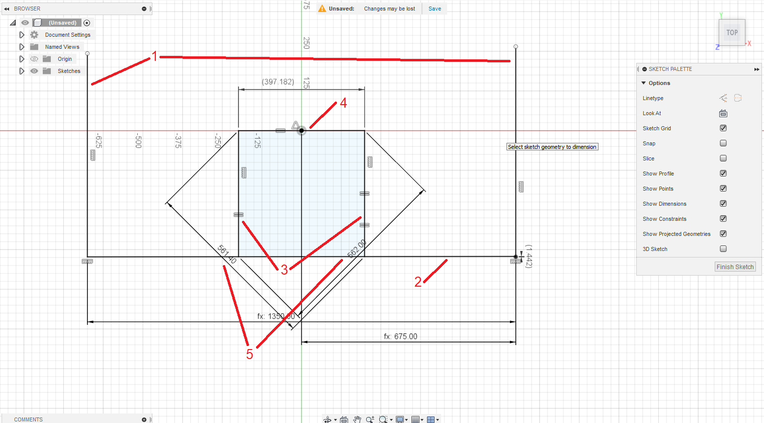
So, an idea. CAD (In this case, Fusion360, but I could do it easily in FreeCAD, too) will let you specify points not joined by a line.
-
Draw 2 lines, and constrain them to be vertical. Their length does not matter, but “long enough” is a good idea. Constrain the lower ends of both to be horizontally equal. Define the distance between these to be the distance between the belts of your LowRider. (In my case, 1350mm.) I further constrained one to be of half that distance from the origin to venter them, but it’s not vital that you do so.
-
Now draw a line between the base of one of these lines, and a point (NOT at the base) of the other line. This must not be constrained to be horizontal, and only the one end should be coincident with the base of the first lines.
-
Add 2 more vertical lines projecting off of this skewed line. these should be constrained to be equal length to each other, or, if you know the exact size of a test rectangle, you can use that, but what is important is that they are the same, and vertical.
-
Add a line connecting the tops of those 2 lines. I constrained the center point to be at the origin, but this isn’t vital, it just makes the model jump around a bit less. Constrain this to be of equal length to the sides. This should form the square in the diagram above.
-
Dimension your parallelogram from corner to corner in both directions.
-
Add a “driven” dimension to the non-constrained edge of your sketch to be the distance from the bottom of your belt line to the intersection of the bottom line and the belt line.
Enter your corner to corner measurements, and the driven dimension will tell you exactly how much to adjust your endstops by. The more exact you are with your corner to corner measurements, the better a result you’ll get. There MAY be a way to get it to give you positive/negative numbers, but I found just having the right number to make the adjustment a big help. The rest was my ability to accurately read the actual measure off of a tape.
I hope this helps people!