Okay, it’s time to start documenting my home built laser machine. This is a fork of the previous posting Upgrades to $79 Amazon Laser - JL1
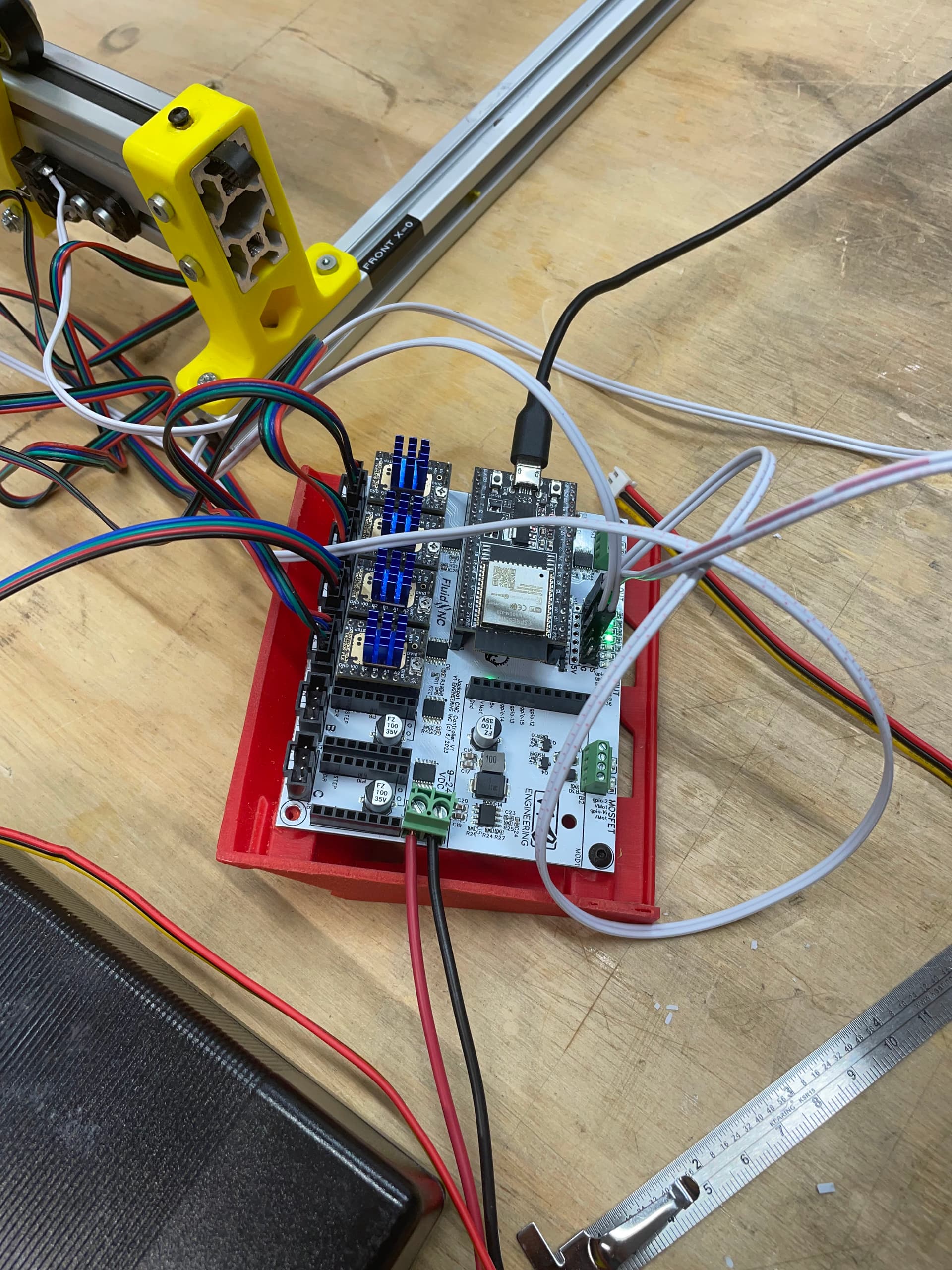
I was originally intending to just stretch my Cenzo JL-1, and put my NEJE a40640 module on it. After realizing that I didn’t really want to lose the portability of the little JL-1, I just installed my BDring FluidNC TMC Pen/Laser controller on it (Thanks to all of you who made suggestions on where to deploy my various controllers).
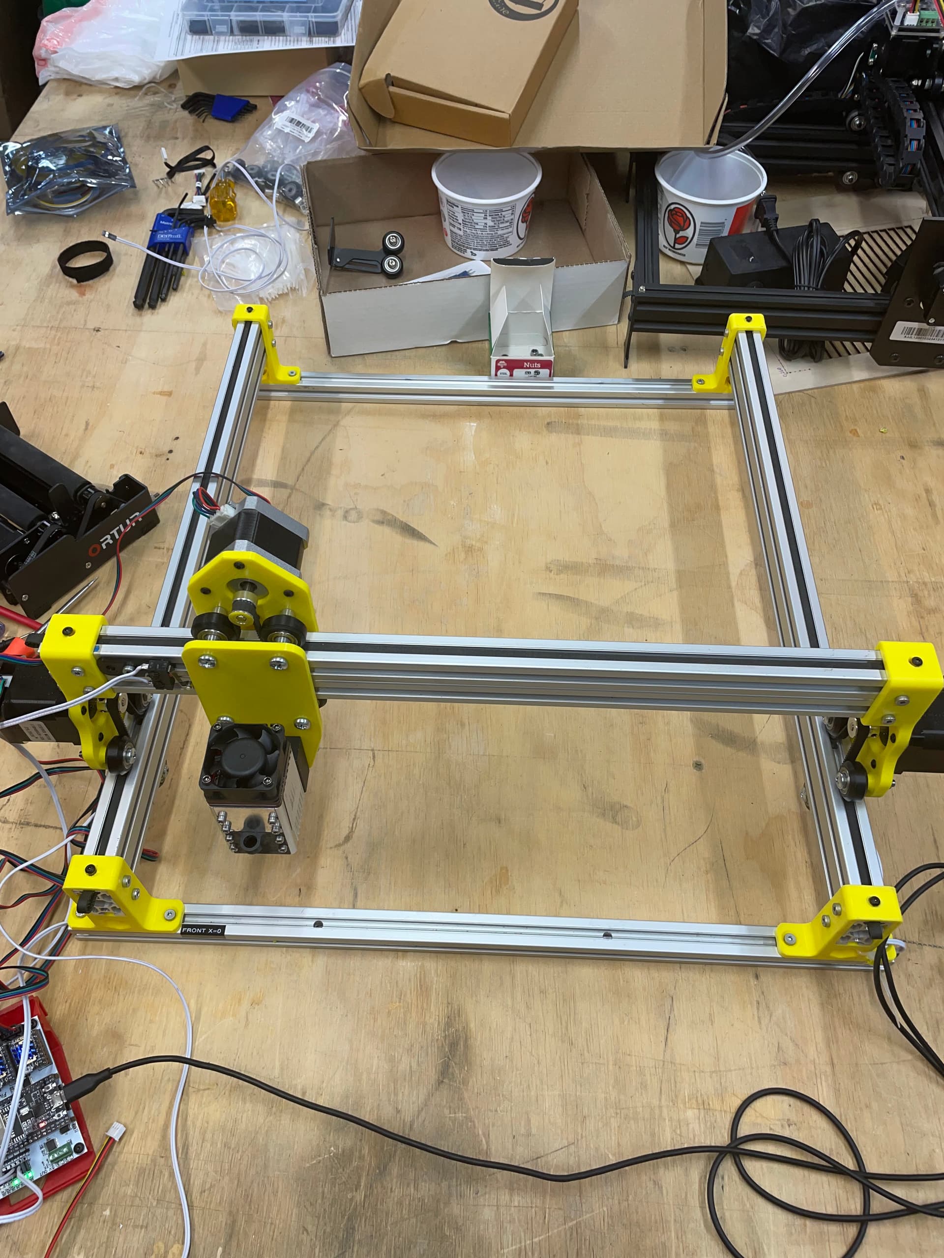
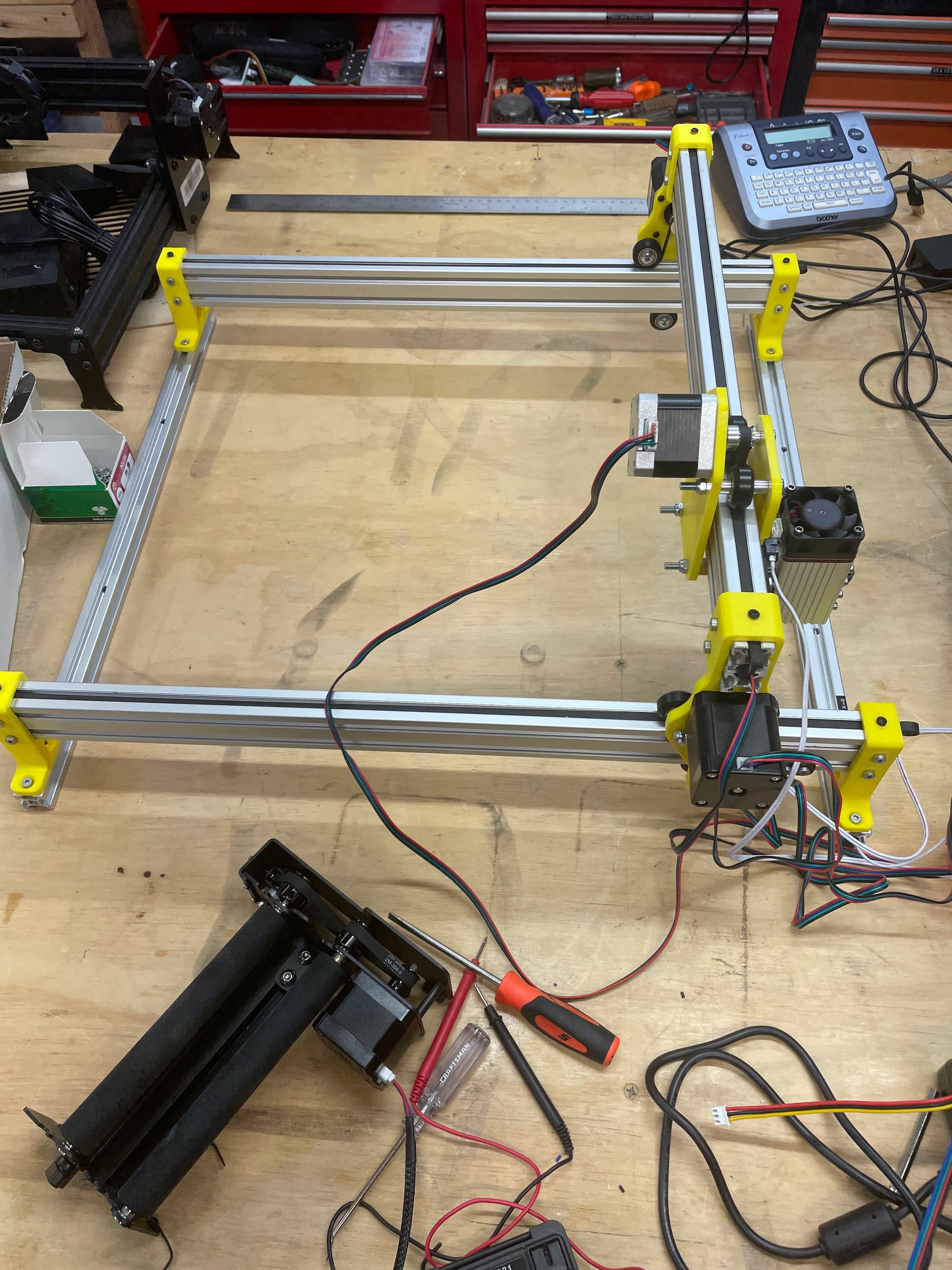
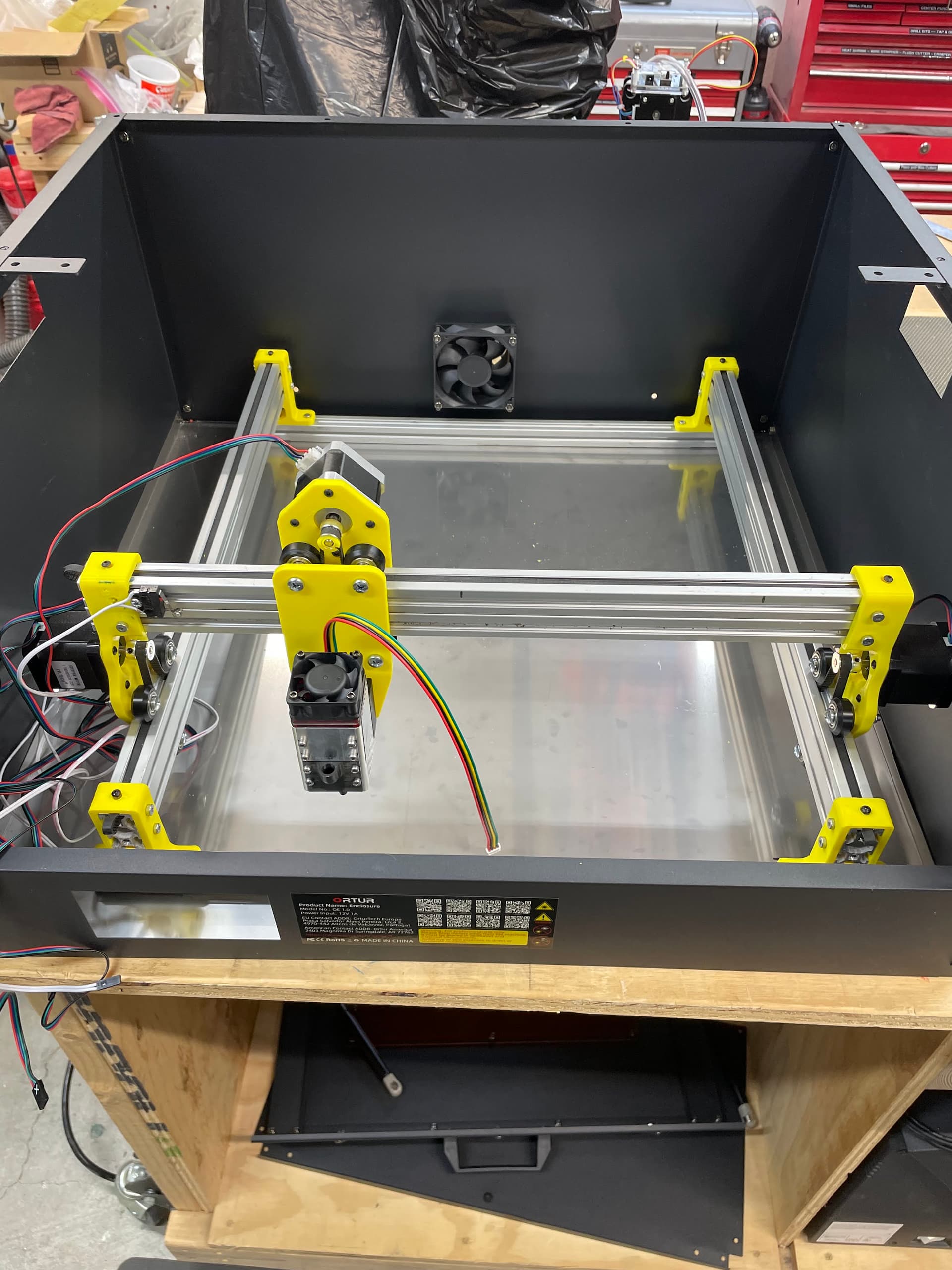
So I started with a simple design from Thingiverse. And made a few changes (don’t we all). I did redesign the X-axis carriage to make it a bit more rigid. The work area is 400x450.
I started with the LowRider3 FluidNC Config.yaml and it didn’t take too long to get it modded to start moving the carriage.
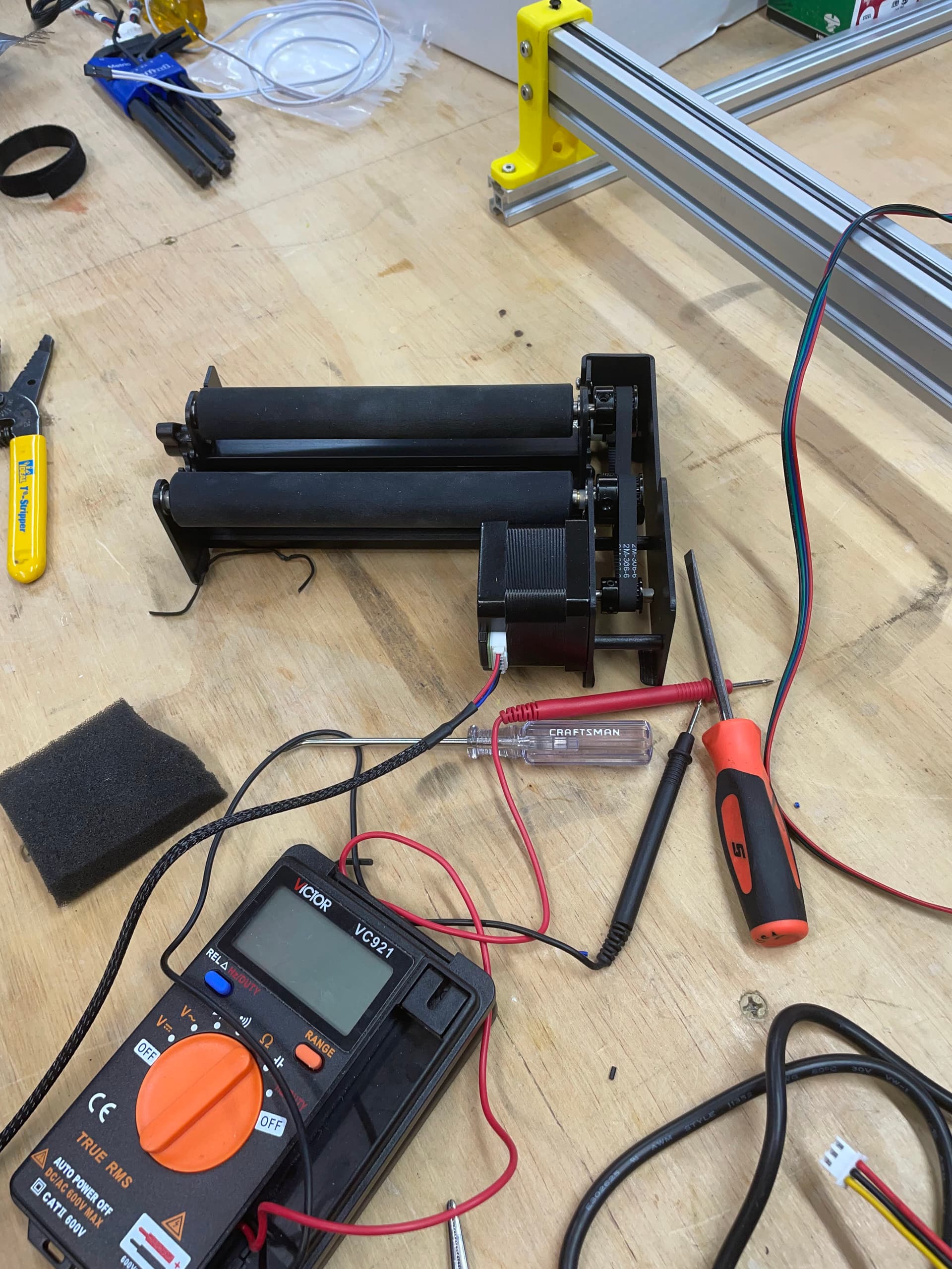
At this point I can move all the motors, they home correctly, and I have a rotary axis that at least works when I enable rotary in LightBurn.
None of it is calibrated yet, that is tomorrow’s task along with connecting up the laser.
I do have a question about the MOSFETs on the Jackpot: the documentation of the board says they can source 2.5 amps each, the NEJE documentation says it need 4A, Can I draw power from both MOSFETs, in parallel to supply the laser?
It’s late tonight so I’ll have to post picture (and video) tomorrow.
Mike B. @Ryan , @jeffeb3 If this need to be moved to another topic category, please go ahead.
A couple years ago I bought two pieces from Amazon, the exact product is no longer offered. I then built a frame to hold it. I still have one left and I plan to just cut it to fit the the bottom of the Ortur enclosure.
No. Most lasers hook directly to a power supply and are only switched with ttf/pwm. If yours is not that way I would look into an SSR, that can be switched from any of the Jackpot outputs.
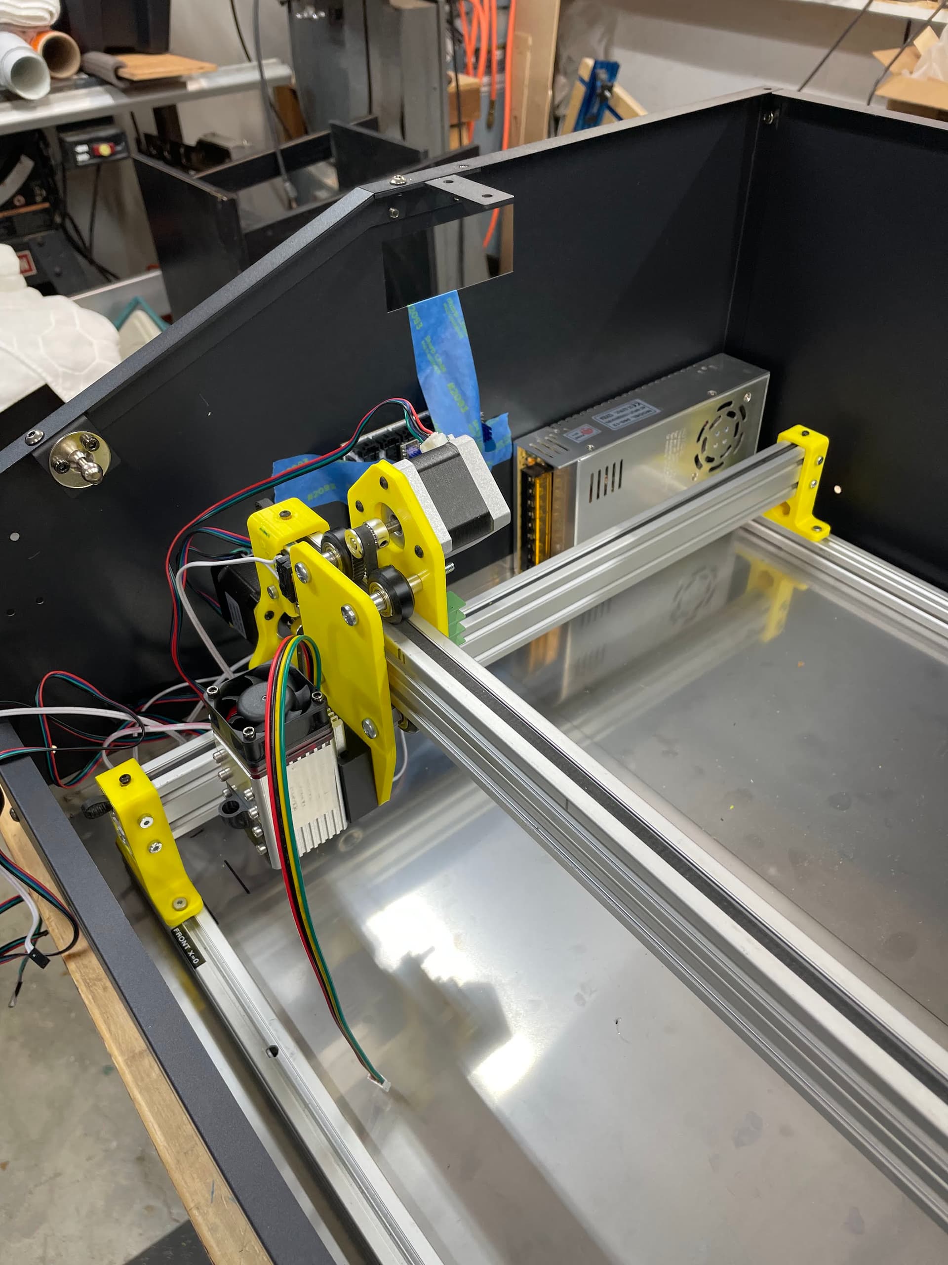
Note that the X Carriage is the major change I made to the design. This allowed me to hold the wheels on both sides, without the stepper or the Z-axis adjustment conflicting with each other. I also installed 3mm inserts into the upper surface of the “legs” to allow me to clamp the belts.
No the parts are from the design linked in the first post. Rather than mount them to a board, I attached the legs to a length of 2020 in the front and rear.
All functions are working but no fine calibration has been done.
The completed frame and X-axis carriage fits into the enclosure (Ortur for the Master 2 system they sell). I did need to position the frame so the X-axis carriage doesn’t contact the cover door when the laser is homed to min Y.
It looks like I need to make a modification to the forward X-axis carriage to include most of the base elements for a @dkj4linux Manual Z-axis. I have most of the parts, but I lose too much Y travel if I bodge it onto the current forward carriage piece.
IMO Mike (I have the Ortur 2) I would not put the power supply in the same enclosure as the laser and materials being ‘burned’. Ortur’s power supply is a power brick, similar to Ryan’s, and it would be outside their enclosure. In the first design they had the controller on the outside, and the one you have the controller was on the inside, and I questioned how much the controller would attract smoke particles.
If I was able to source their enclosure I was going to increase the size of the exhaust fan, and make sure it pulled fresh air over the controller. As long as you have that power supply pulling outside air over the electronics maybe you’re safe. But if it’s positioned as is, with no outside holes, I’m guessing smoke and particulates will shorten the life of the power supply. Of course in one or two years, odds are you will be upgrading to a more powerful and cheaper laser anyway, so….
The CO2 enclosures have the electronics in a separate chamber, not well isolated from the burn chamber, however the exhaust fan is pulling the smoke away from the electronics chamber.
Of course I’m a bit CDO, so it’s just an opinion, but I don’t like smoke around my electronics. Have a tough enough time with the CB above the laser itself, but I understand it’s not an option to place that one far away from the laser.
I’m more disappointed in the diode laser manufacturing not using an enclosure more like the Ortur metal enclosure you have or the K20. Maybe I’m more concerned than I should be, but using my Ortur with a enclosure, I was surprised how much light was bouncing off the walls of my shop walls while engraving/ cutting wood, and wondered how much this was a issue. I haven’t been using it, because I want to purchase an enclosure or build one. Also been debating on a CO2, which by default solves my enclosure issue.
So two points of interest here for me.
Wasn’t aware of Vevor lasers, so thanks Peter for bringing this to my attention. I should have thought to look. Draw back is that the machine is a bit more at the US page for the Vevor, and at the time that I looked, all their enclosure machines were sold out. Not sure what that’s telling me (if anything).
Another interesting thing, I knew they existed, but wasn’t aware of them yet in the consumer market, but I was just introduced to a RF laser last night, which is without the required water cooling like a diode laser (one of my points of interest due to freezing temperatures in winter). So found another rabbit hole to explore. Kind of intrigued of the near power of a CO2, in a CO2 enclosure, without the need for water cooling / laser tube replacement. Still researching if it’s the right fit for me.
I know all lasers will die with time, I just remember changing high pressure sodium bulbs in a movie theater projector (12 of them) with a heavy apron, face shield and gloves, and the glass tube for CO2 has always triggered a feeling I’m choosing to avoid unless I have too. (ha)
EDIT: RF laser was the intro last night (but not fiber?). A CO2 laser is IR.
Yeah, that doesn’t help the feeling one has, after years of training and discipline around HPS. Certainly things I’m always going to treat with respect regardless if I think it’s capable of hurting me or not.
Thanks Steve, I was wondering, but you have convinced me.
I stayed up late last night to do a re-mix on the @dkj4linux Manual Z-axis. I’m using FreeCAD and while I’m not too bad designing from scratch, it took 3-4 YouTube videos to get the whole process to make the .STL into a solid I can modify in FreeCAD. This afternoon, the modification will be on the printer!
Well… I was never really able to get the STL converted to work in FreeCAD. I think the problem is that there are just too many facets on the STL and the program just can’t quite handle eliminating all of them. It’s probably just something I didn’t do (or maybe what I did).
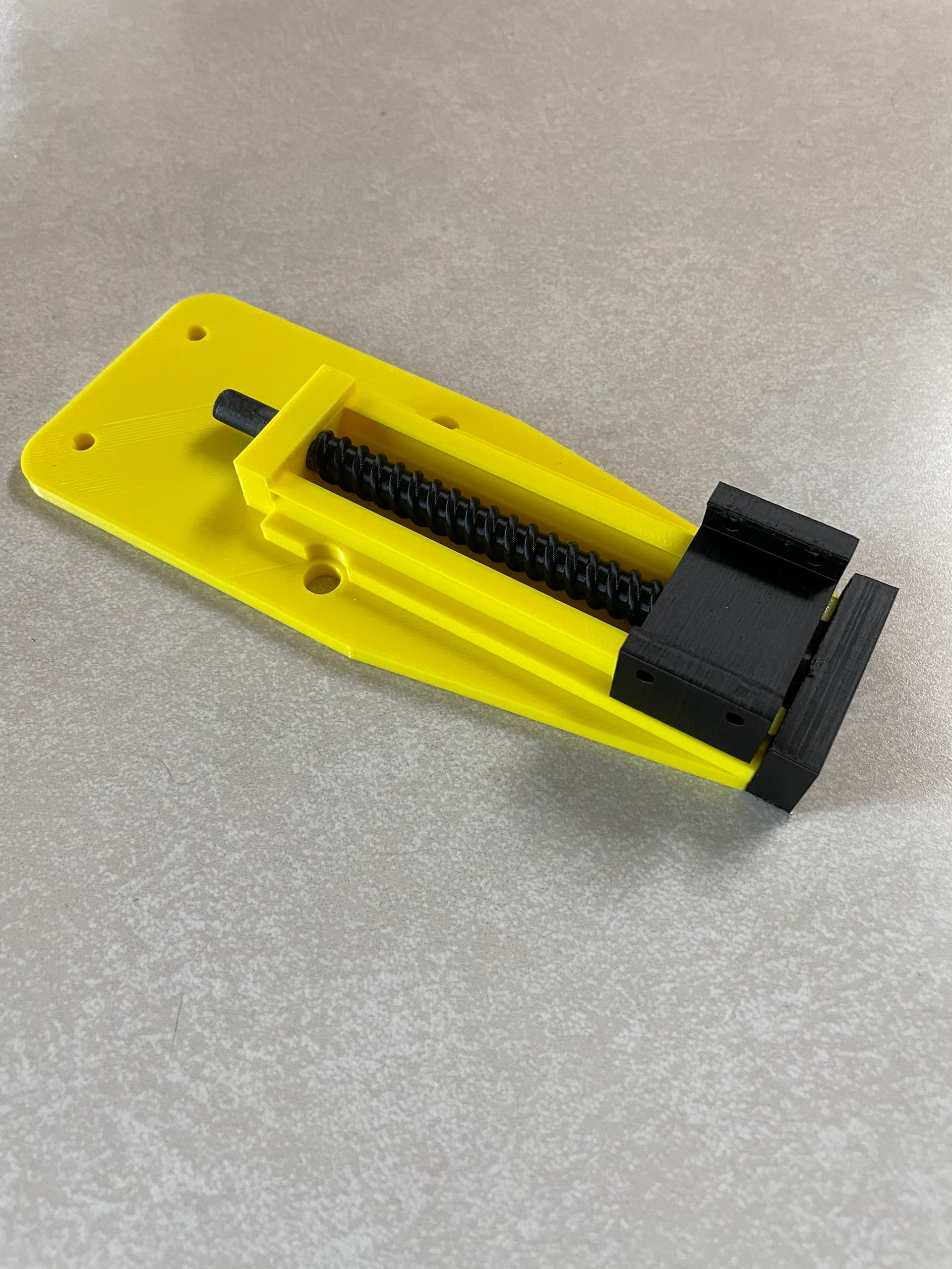
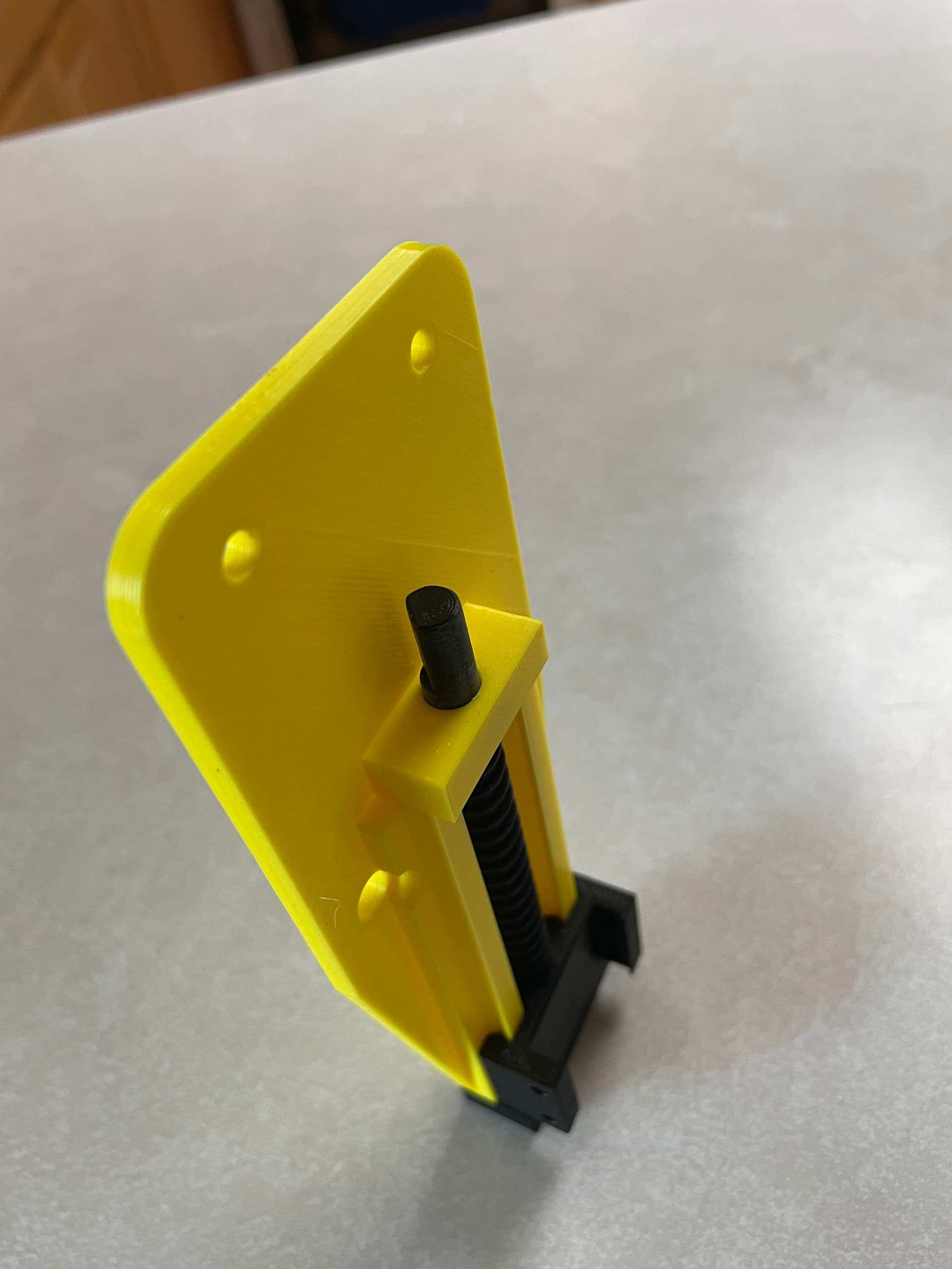
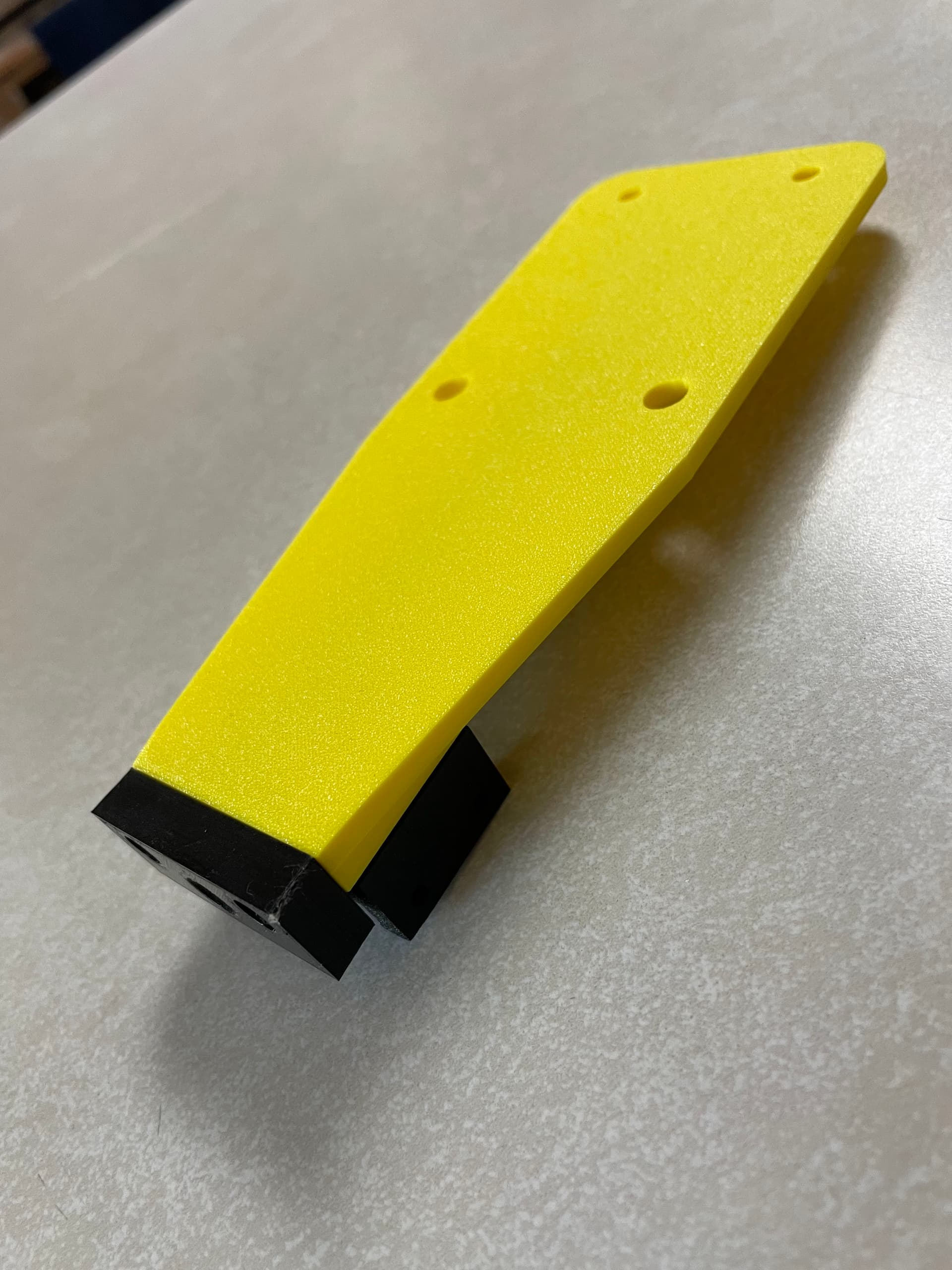
So to solve the problem, I took the 3d printed part that @dkj4linux designed, measured ALL the dimensions and recreated it in FreeCAD. Then I merged it with my modified X-Axis carriage and this is what I got:
The black parts are exactly from Dave, and the yellow part is the new front part of the X carriage. The design takes very little of the Y axis space. however as you may notice, the knob that is supposed to fit on the top of the screw cannot be fitted with the available space. The screw axis is too close.
Seeing all the hours I spent trying to get a simple part into FreeCAD, I need to ask you, @dkj4linux , for a favor. Would you be willing to make an extended length version of the Z-thin-r1-leadscrew? I need upper, unthreaded part 45mm longer and don’t need the flat. If you are willing to do that, may I also include it when I do a remix model in Thingiverse and Printables?
I plan to do that as soon as I have a completely working system.
TBH I’m not exactly sure which manual Z-lift you are drawing from but this Z-lift has the same leadscrew and an extended knob that can easily be further extended. I personally would prefer extend the knob shank rather than the leadscrew, as it’s a pretty spindly print already. The included short and tall knobs in that Printables model are 23 mm and 45 mm tall, respectively.
Sadly, I’m not facile enough in FreeCAD to readily extend the part but TinkerCAD makes it quite easy… and is usually my “go to” for this type of thing.
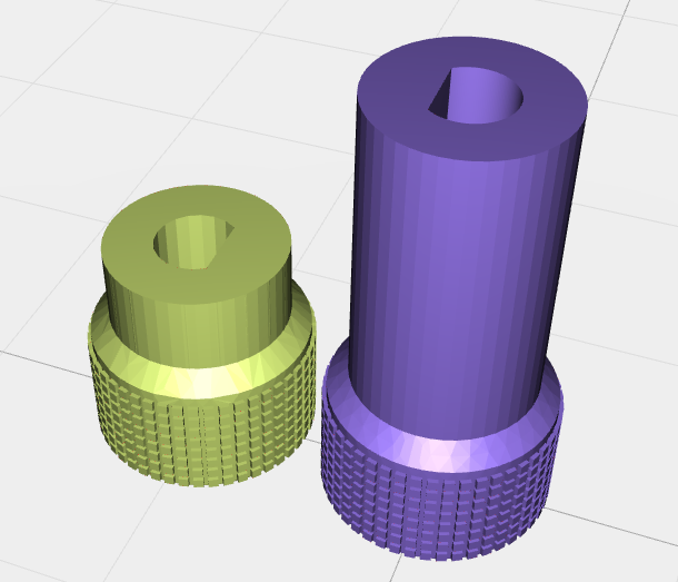
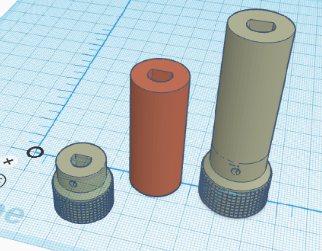
The left-most knob is simply the imported short knob STL… lowered below the origin plane to a suitable cross-section to be extended. I then export the cross-section at the origin plane as SVG. The middle piece is the SVG imported back in and then stretched as a separate piece to whatever extra height is desired. The right-most piece is created when the original knob and extension (left and middle pieces) are aligned, merged/grouped, and then exported as STL. If necessary the extension piece can be trimmed before grouping to a thinner wall as well.
If you still wanted to extend the leadscrew, you could use the same procedure as above… with the imported leadscrew vs the knob. It’s possible the leadscrew’s complexity might cause TinkerCAD to scold you – or crash – but the short knob seemed to work okay. I didn’t extend the example knob to a specific length (it’s currently 67 mm in height) but if you’d prefer I can adjust it to the overall length you need and provide the STL here in the forum. You’re certainly free to use it and include it in a remix if you’d like.
BTW that’s a straight-forward, clean-looking, laser engraver design you’ve got going. I’m tempted… but really don’t need another DIY machine for my kid’s to have to dispose of, when the time comes.