Starting a new “LR4” build thread.
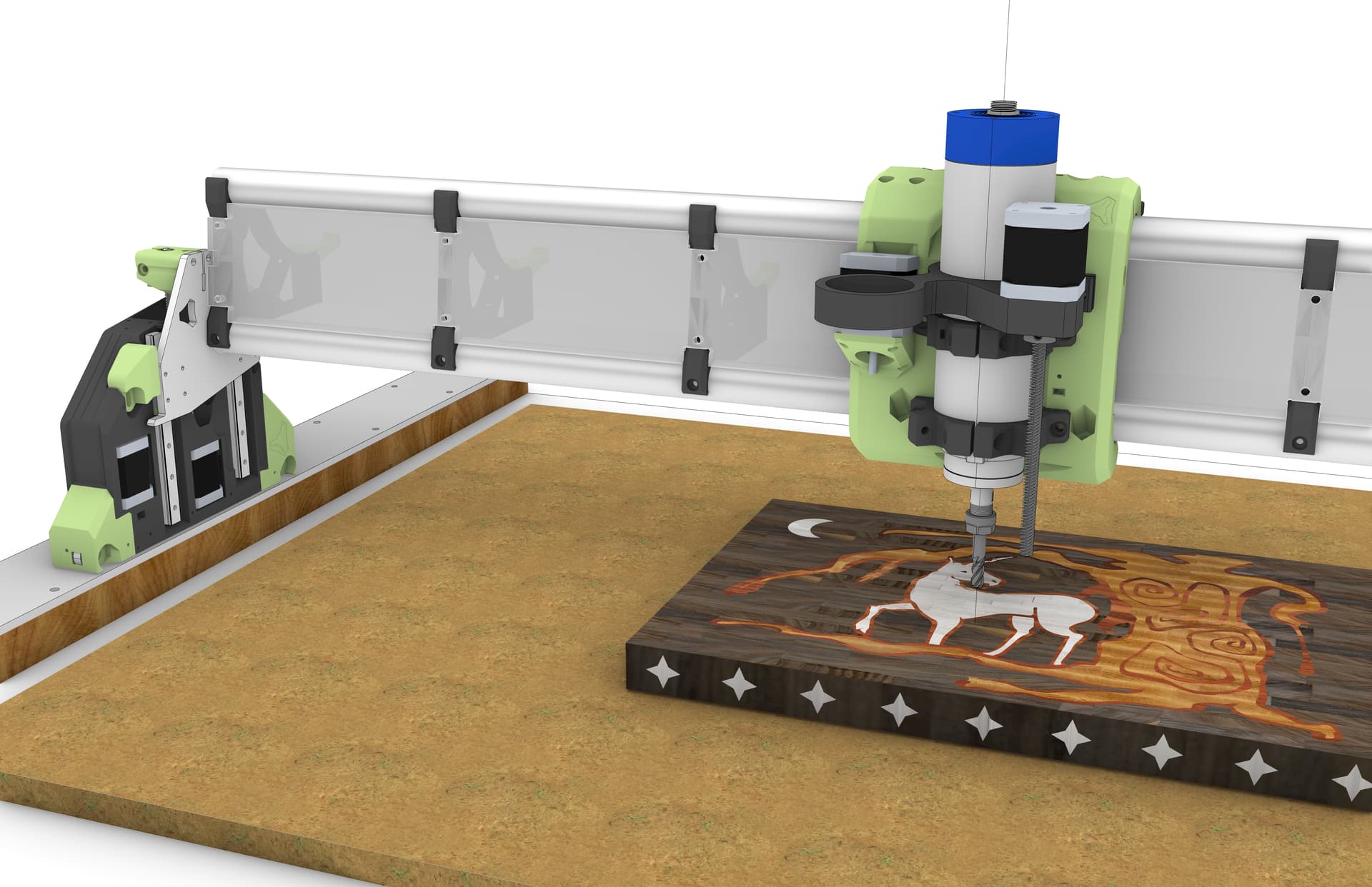
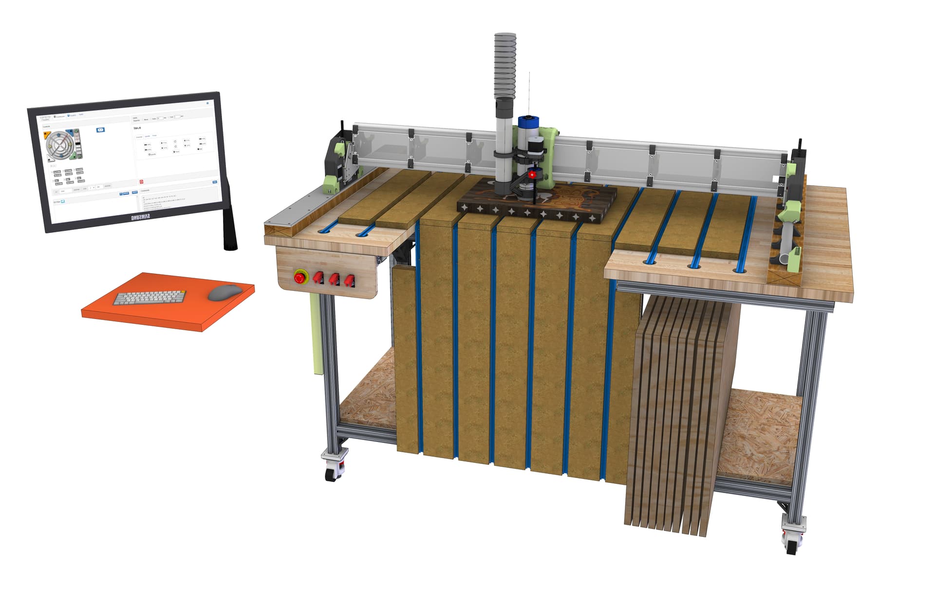
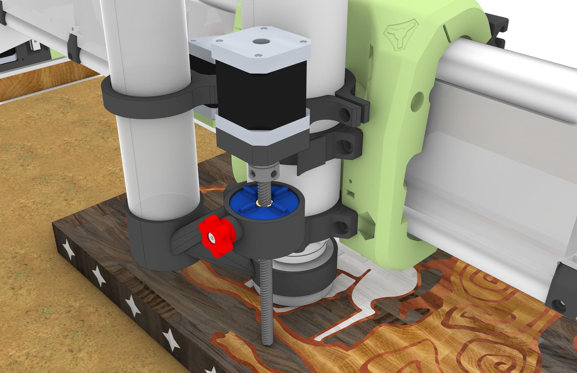
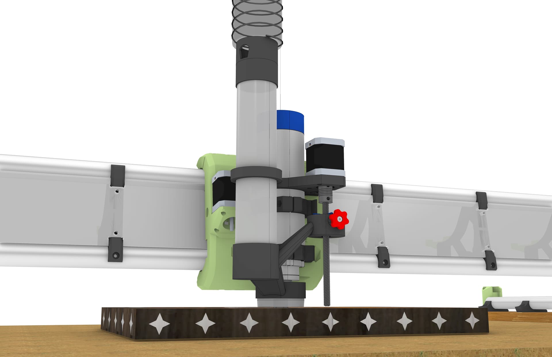
Here are some of my 3D model renderings.
Video of my proposed “z-independant” dust shoe:
Awesome modeling. I love the drop table at the edge, very nice.
Do you plan to extend the table when not using the drop feature? You have the long axis on X, which is generally advised against but maybe for this configuration it makes the most sense.
In practice most of the items I put on the waste board fit within the flat portion. If I ever have a full 48” wide by 24” piece it can just span over the void.
As far as the long “x” axis I figure there are plenty of full 4x8 Lowriders out there that have a 4’-0” gantry and if the machine is sturdy enough for a 4x8 it should work for a 4x2.
I’m facing the gantry in the long direction (+X) is to the right and (+Y) is going away from me on the MPCNC Primo so I wanted to keep the “x” and “Y” directions the same on the LR4 otherwise my brain might glitch and make a costly mistake.
I know I saw a post where someone installed an RGB LED strip below the gantry that was connected to the control board and would light up different colors depending on the run state of the machine.
IE:
In the ALARM state, the LED strip would be red
In the HOLD state, the LED strip would be yellow
In the RUN state, the LED strip would be blue…etc.
But for the life of me I can not find it does anyone know where to find information on how to connect an LED strip to the Jackpot 3 such that different run states of the machine would trigger different LED colors.
TIA
Most use WLED (and a separate ESP), and then they map button presses to the different LED effects. Ex. single button, double tap, long hold etc. You press the button with GPIO.
I believe I found it with Google AI search:
AI Overview
You can control LED colors with a
Jackpot board running FluidNC firmware, often using external controllers like WLED for addressable RGB LEDs (WS2812B) or PWM outputs for simpler RGB/RGBW setups to indicate machine status (Idle, Run, Alarm). Control involves configuring specific GPIO pins in FluidNC and potentially running custom firmware or web UIs (like ESP3D-WEBUI) to manage dynamic color changes based on the CNC’s state.
Methods for LED Control
Addressable LEDs (WS2812B/SK6812):
How: Use a dedicated data pin on the Jackpot board connected to the data input of an LED strip/ring.
Firmware: Requires custom FluidNC builds or WLED firmware flashed onto an ESP32 (which the Jackpot uses) to handle the data stream.
Use: Great for complex effects, status overlays (e.g., white ring around the router), and status indicators.
PWM Outputs (RGB/RGBW LEDs):
How: Wire Red, Green, Blue (and White) channels to the Jackpot’s PWM-capable output pins.
Control: Configure these pins in FluidNC’s config.h file for output control.
Use: Simpler setups for static colors or basic state changes (e.g., Green for Run, Red for Alarm).
How it Works with Jackpot/FluidNC
Status Mapping: FluidNC can be configured to change pin states (HIGH/LOW) or PWM duty cycles based on its internal status (running G-code, paused, alarm).
Customization: Users often fork FluidNC or ESP3D-WEBUI and add “usermods” to the firmware to enable these dynamic color features.
Example: A user might set a pin to 100% PWM for green when the machine starts, then to 50% for yellow when paused, using logic within the firmware.
Getting Started
Hardware: Get addressable (WS2812B) or RGB/RGBW LEDs and wire them to the appropriate I/O pins on the Jackpot board.
Firmware: Compile FluidNC with WLED support or flash WLED onto the controller if desired.
Configuration: Define your LED pins in the FluidNC config.h file and customize the behavior in your firmware build.
Found the forum post - Jackpot + Wled
Thanks
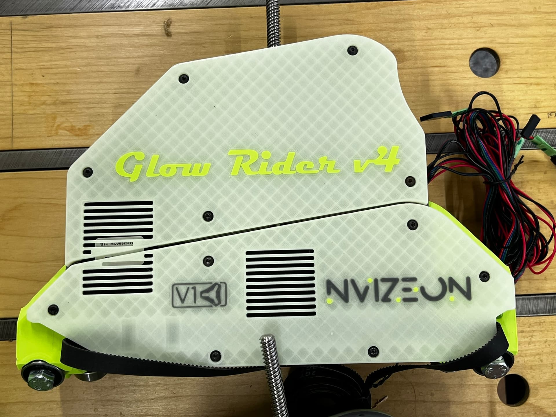
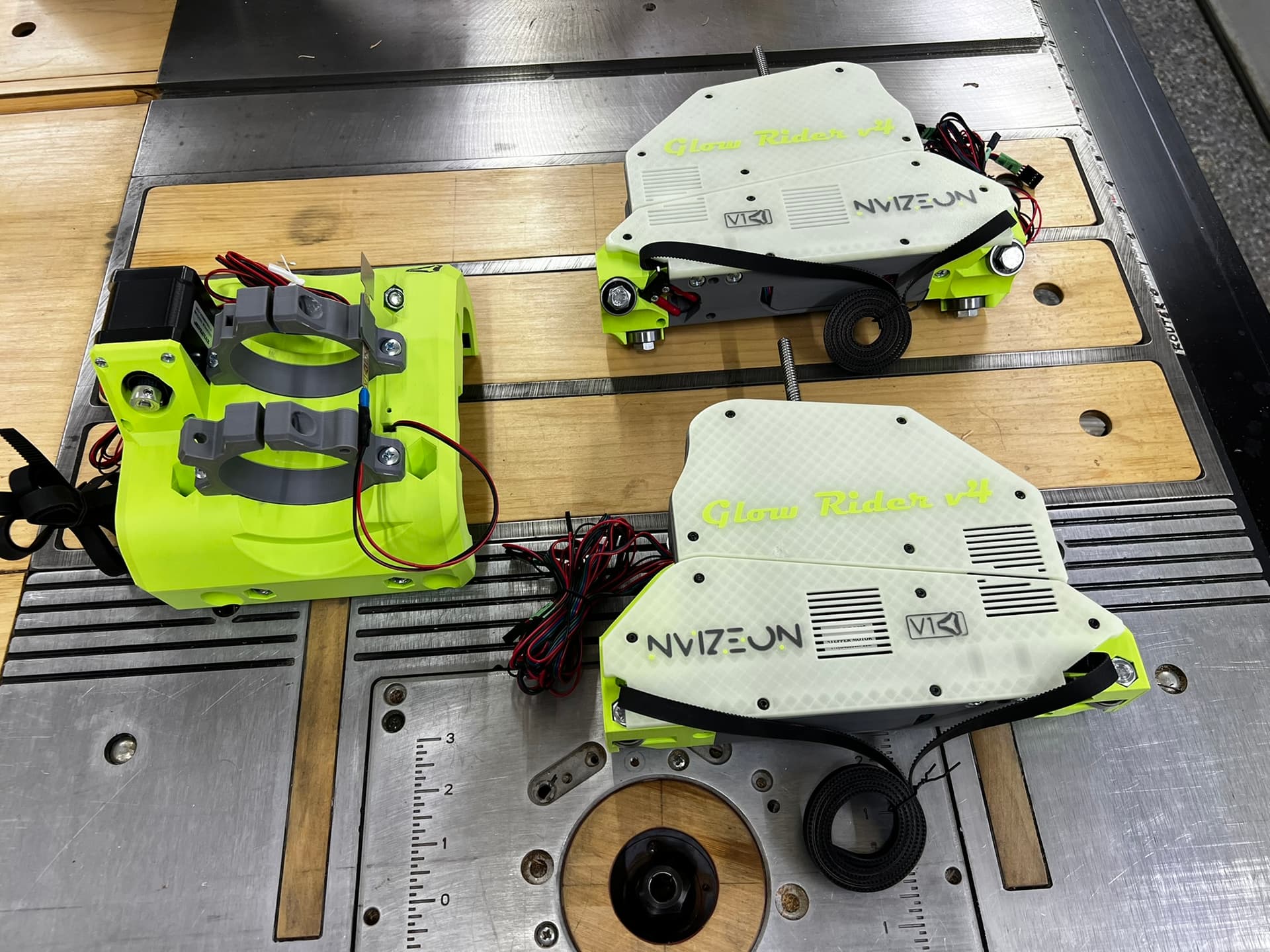
I’m hoping to add this to the Glow Rider v4
Yea, the crazy version of that is me. I created a WLED usermod that connects to FluidNC via Telnet (since it doesn’t really like multiple websocket connections). So, it monitors the status and maps it to a WLED preset.
I’ll probably reach out to you when I get to that point in my build.
My first architectural mentor (boss) had a saying that I will always remember.
“You’ve got to know what you don’t know”
IE: in my field of work as an architect it’s best not to “guess” when it relates to buildings that can collapse and kill people. so If you don’t know something find someone that does.
As it relates to software coding and electronics. I’m gonna need to phone a friend ![]()
Didn’t @Jonathjon have an easier version?
All the ones with color changes that I know of involve WLED in some way. You might be able to tie it into some output pins instead of having custom WLED firmware. That at least gets you run/hold/alarm states. That would be similar to how Ryan did it (Jackpot + WLED linked above).
I have a different board so I need to figure something out.
I did it with klipper an their neopixel plugin. It just works, but getting everything configured takes some time and is a different hardware set, so you are better off with the jackpot and the wled.
I thought someone was talking about this a while back. The idea was to make the LED’s light up like a progress bar. It would light up at one side of the gantry and as the job hit 50% complete lights would be halfway across the gantry and so on. I have a fluid dial pendant, and it has a progress bar running while a job is cutting. could that signal be picked up to light LED’s on the gantry for a progress bar? I know just enough about this stuff to really screw things up but I’m learning. Your Lowrider looks great!
That’s definitely feasible to add. What it currently does is highlight the current X position with white LEDs with whatever “run” preset playing across the rest of it. So it basically tracks the core.
Why is this advised against?
My LowRider will be 2’ x 4’, and the specific instructions on the Lowrider page state:
“Width (X axis or “Beam”) should always be the shorter axis.”
As I noted above, I’m currently using an MPCNC Primo with the “x” axis as the 48” and the “Y” axis as the 24”, and the table is already made and positioned such that my access to the machine is along the front (48” inch wide) with the cut-out for vertical work clamping.
Since I’ve seen plenty of “full size” 4’x8’ machines with the “x” axis as the 48” dimension, I presume that the Lowrider v4 is capable of having a “beam” that is 4’-0” Long the “y” axis is just the 1” EMT which is hard mounted to the table and the the other side is just the rollers running along the table so from a rigidity standpoint the “BEAM” is the weakest item since it must “span” from two end bearing points and additionally it must support the spindle and is the first point of deflection when the spindle is pushing down into the work piece as well as the first point of load transfer for lateral loads when the endmill is moving in the x or y direction through the work piece.
So I understand the “recommendation” to make the shortest axis the “beam” “X-axis,” but what fun would conforming to rules be? ![]()