I’ve been playing around with making an aluminum Turners Cube on the MPCNC and found myself wanting a way to easily set the origin of the machine to the corner of the work. For this project I’m mounting the workpiece in a 3 inch vise. I replaced the metal vise jaws with 3d printed ones to avoid marring the aluminum. After squaring the stock, the Turners Cube requires making the same cut on all 6 sides of the cube. I realize that I could have mounted a stop on the vise to get repeatable clamping but what fun would that have been?
I started by trying to modify Ryan’s firmware by enabling G38_PROBE_TARGET, FIX_MOUNTED_PROBE, and Z_MIN_PROBE_USES_Z_MIN_ENDSTOP_PINwith no luck. I also saw elsewhere on the forums that some G38.Xwas broken for the firmware versions that most of us use. I ended up merging the latest bugfix-2.0 branch of Marlin into Ryan’s firmware and still had no luck. A couple of hours of debugging C++ macro hell later on my updated firmware (seriously, how anyone keeps up with the amount of preprocessing in marlin amazes me) I found that manually configuring Z_MIN_PROBE_PINfixed my issues. Z_MIN_PROBE_USES_Z_MIN_ENDSTOP_PIN seems buggy and doesn’t set the appropriate pin to be monitored by G38. Last of the nuts and bolts that I’ll mention is that for anyone wanting to dive any deeper into Arduino than modifying config values should consider setting up a proper IDE and tooling to make life easier. I took a step away from my usual linux dev tools and followed this guide to get going.
It’d be cool to see this supported out of the box for MPCNC users. Is there anything keeping to to the version of marlin that Ryan ships his boards with?
With newer builds of marlin, yes. The latest builds support manually setting the Z probe pin. Be sure to read through the docs before tweaking that setting.
Yeah, the imgur video in the first post shows using G38.2 for X, Y, and Z.
Thank you for your post. It helped me some in configuring my own Probe sensor.
To help others with specifics, here is what I did.
Download Marlin 2.0 from V1’s git listing with respect to your board.
Down load the correct version of Aurdino need to compile it.
Compile the software - as is - and get it flashed to the board.
connect up motor to each XYZ and verify movement commands work.
Check endstop status using the M119 command.
If you have compiled this as is, it should only show 3 status
X_min, Y_min and Z_min as open.
Connect up what ever you are going to use (eg 2 wires) to the Z min end stop pins (Signal and Neg pins, do not connect the positive pin).
Short them out. and repeat M119
The Z_min should now show as triggered.
connect the board back to your PC and the Arduino software.
Open the configuration.h file.
Disable/comment out the line #define Z_MIN_PROBE_USES_Z_MIN_ENDSTOP_PIN
fine your board and open the file for your boards pins.h file. (for example for RAMPS 1.4 this is “pins_RAMPS.h” and locate the line where #define Z_MIN_PIN and copy that number.
Back on configuration.h edit/enable the line #define Z_MIN_PROBE_PIN insert number from PIN.h
find and enable the setting FIX_MOUNTED_PROBE
Save configuration.h
edit configuration_adv.h. Find and enable #define G38_PROBE_TARGET
15 . Save
compile and upload to the board.
connect to the board and issue M119 command and you should now see
Recv: Reporting endstop status
Recv: x_min: open
Recv: y_min: open
Recv: z_probe: open
Using your Z_MIN cables short them out and test M119 again and Z_Probe should trigger.
(un-short the probe)
Using a motor connected to the Z axis, make sure it moves (normal move commands)
Enter the command G38.2 Z20 and after hitting return quickly short out your Z Probe cables and the motor should stop.
Check all the other motors also work with the probe direction.
A) Don’t know. I did this on the RAMPS board with Marlin 2.0.
However I browsed to the Archim Series 1 source (link provided in the V1 firmware page), and drilled down to Marlin > Src > pins > pins_ARCHIM1.h and the first page on this shows that it is #define Z_MIN_PIN 31 // PA7 MIIN ES3
B) I don’t know. I documented what I did to get it working, I didn’t spend anytime under the hood about why I had to do it. Note: If I enabled B the probe stopped working on Z MIN
lastly - Dont know. Again. I did mine on the RAMPS 1.4 download. I don’t have your board to test/experiment with.
The key is to comment out “#define Z_MIN_PROBE_USES_Z_MIN_ENDSTOP_PIN” and uncomment the line further down “#define Z_MIN_PROBE_PIN 18 // Pin 32 is the RAMPS default” Notice I changed the pin to 18. If you look in the pins folder for your board you’ll be able to find which pin is the z_min pin and use it. It’s the workaround for the bug mentioned higher up in this thread.
I’ve got the Z axis working great with the above directions and G38.2, but I can’t get the probe to trigger for X and Y? M119 Shows that the X_MIN and Y_MIN trigger fine manually. Is there somewhere I need to define pins for X & Y probe? I can’t see it anywhere in the config.h.
X_MIN and Y_MIN are not used for G38.2 probing in the X and Y directions. Those use the probe pin, same as the Z probe.
I have a faint memory of there being a bug that only allows probing in the positive X and Y directions, and probing in the negative X or Y directions don’t work. Not sure if that memory is correct or not, or if it has been fixed since then, but try probing G38.2 in positive X and Y first to see if those work.
I’m using the z-max pin on my RAMBo for the G38.2 probing and the z-min pin for the G28. The G38.2 is a lot more work (everything is scripted) and a PITA if you change your origin…but I am self-taught (by doing a lot of reading) so there may be a better way.
…and there is a better way, by switching to relative positioning in the script after locating Z0. Trying to figure offsets from any random given XY position without relative positioning is a chore otherwise.
; set corner of workpiece at known approximate Xx Yy, Z above workpiece.
; assumes 1/4" (6.35mm) probe dia.

G90 ; absolute positioning

G28 X Y  F300 ;home XY
G92 Z0 ; set Z, start with a known value

G00 X161 Y96 F300 ; location to probe for Z. Add 20 to approx. Xx Yy location
M0 Connect probe ; and click to continue. Assumes LCD is attached.

G38.2 Z-94 F300 ; probe Z, look for touch off, fault if not found within 94mm
G92 Z0.105 ; set Z0, allow for 0.105mm aluminum tape
G00 Z5 F300; raise Z 5mm

G91 ; switch to relative positioning

G00 X-30 F300 ; back away 30mm for X
G00 Z-11 F300; lower Z, probe for X 6mm below Z0
G38.2 X30 F300 ; probe X, keep reasonable probing distance

G92 X-3.280 ; set X0, allow for half of 6.35mm probe diameter + 0.105mm Al tape

G00 X-2 F300 ; back away from touch off
G00 Z11 F300 ;  raise Z
G00 X20 Y-30 F300 ; go looking for Y

; repeat for Y

G00 Z-11 F300; lower Z, probe for Y 6mm below Z0
G38.2 Y30 F300 ; probe Y, keep reasonable probing distance

G92 Y-3.280 ; set Y0, allow for half of 6.35mm probe diameter + 0.105mm Al tape

G00 Y-2 F300 ; back away from touch off
G00 Z11 F300 ;  raise Z

; switch back to absolute positioning
G90

G00 X0 Y0 Z5 F300 ; done!
I haven’t really thought of a good use for G38.2 positioning, but it’s kind of fun to watch. Also, I enabled M114_DETAIL in firmware so instead of setting X0/Y0, I modified the script above to report the touch position (M114). Of course, I have to add the probe/tape offset to those numbers to get an accurate positioning, but if I accept the offset as is and record it, then set X=0 Y=0, I can go back to that corner, so it’s kind of a reminder to write down the corner position if I need to go back to it.
I would be hard pressed to say why this is any better than simply jogging over to a corner with a joystick (thanks, @jamiek !) other than I have a dust shoe and it’s hard to position the probe accurately. I also have a corner square printed that I can pop into a couple of holes in the spoilboard and use that, but sometimes the material corners are kind of beat up. Lots of ways to do the same thing…
EDIT: woke up this morning thinking that reporting the XY position is only relevant if you have dual endstops.
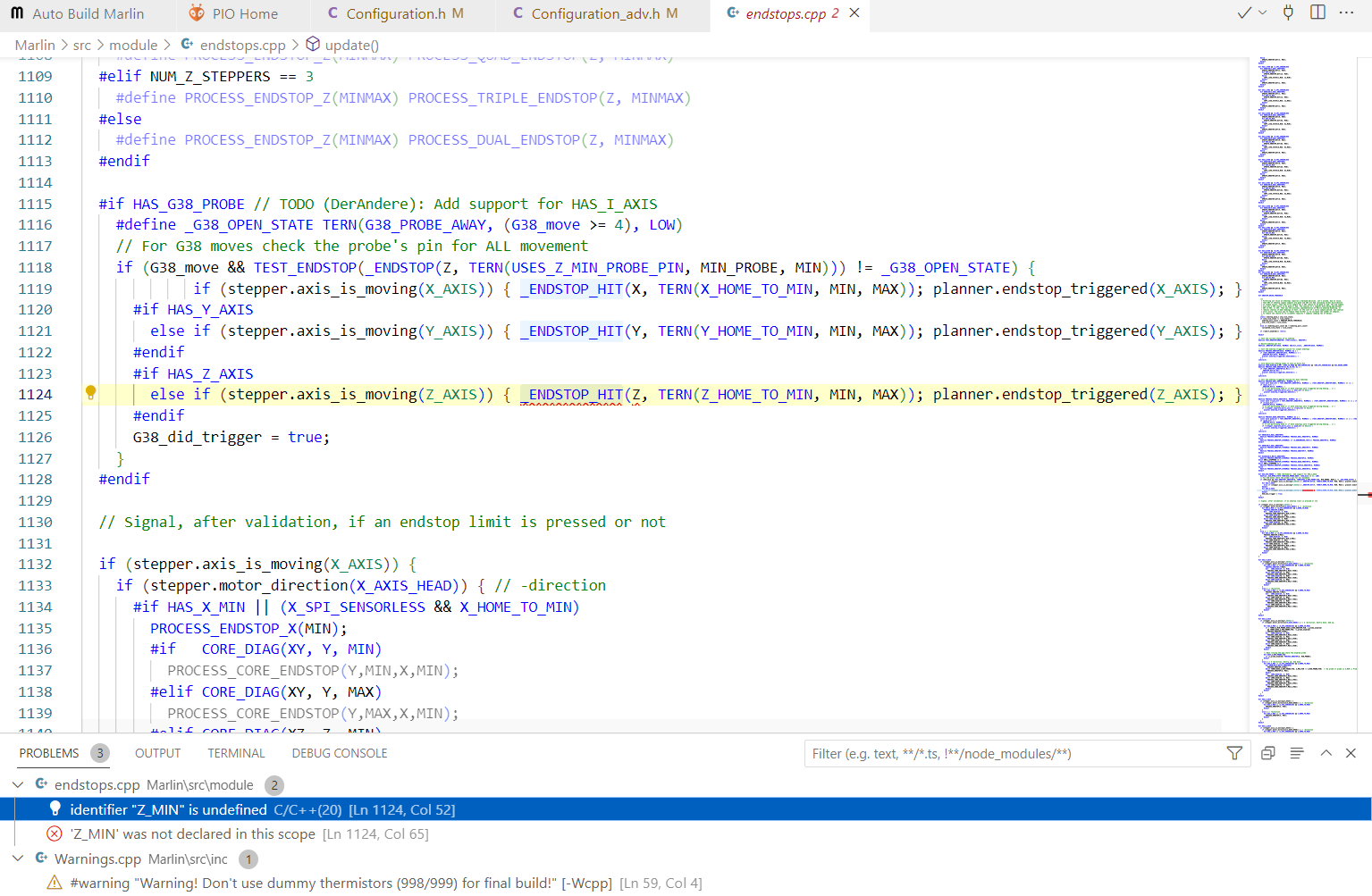
Hey, I was trying to configure my marlin firmware to be compatible with g38 X Y Z probing, but after editing the code and trying to build, it says “one failed” and there are these problems:
When I was enabling G38, I ran into that problem. And when I attempted to address the Z_MIN issue, other errors popped up. In the end I got it working, and the exact recipe (lines changed in configuration.h and configuration_adv.h) I used can be found in this post. Note the specific recipe I outline creates a safe zone for homing Z. This works well with my “bitsetter,” but it will prevent you from using G28 with a touch plate. You will need to use G38 for any probing tasks.
Thank you so much, I just uploaded the code and it worked swimmingly! I have been chasing this for months (Maybe even a year at this point) And I am so grateful for your help! I may have some more questions soon as my curiosity continues to grow!
And my curiosity has sparked. I heard that estlcam has a feature that probes X, Y, Z, and then probes X/Y again to find the angle of the material. I I was wondering if there is any way to make this work with Cnc.js (Code changes the the firmware). This isn’t super important, but it would be a nice function for if i ever need to be extremely precise.