I finally found the time to explore how to have bitsetter-like functionality on my Primo. Below is a description of my implementation based on my work process.
Specifically:
- I never include bit change code in my g-code files. This means I have a separate g-code file for every bit change.
- I never include a G92 X0 Y0 Z0 in my g-code files. Each job expects the machine to have the origin relative to the stock set before the job is run.
- I always use the top of the stock as my reference in CAM. If I want to use the spoil board as a reference position when cutting, I do it manually by first touching off the spoil board, moving Z up to the stock thickness as defined in the CAM, and setting that as Z=0. This means that Z=0 is a safe place for the router bit.
My process/rules were created to avoid repeating a series of failures/disasters I experienced early in my use of my CNC.
To make bitsetter work I had to: 1) find or make some sort of mechanism, and 2) I had to modify the firmware to enable probing, 3) create scrips for the process. The thing I struggled with most was figuring out a simple but flexible process. I ended up with five scripts:
- Home XY in machine space
- Home Z in machine space
- Probe (if using a touch plate)
- Bit change
- Restore job position
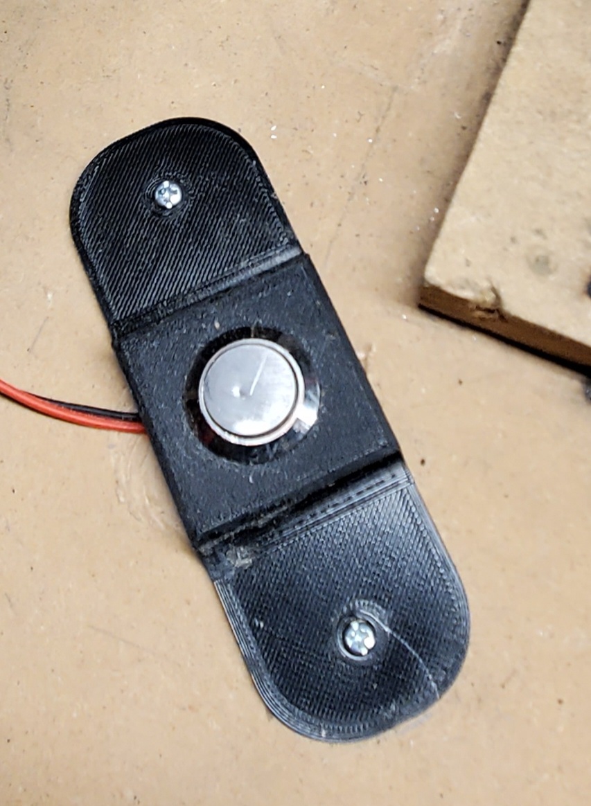
For a bitsetter mechanism, any device that completes a circuit, and can be mounted at a specific location, can be used. A touch plate can be used, but then the logic would need to include prompts for attaching and removing the clip. Yuck. The commercial versions of bitsetters are very expensive ($120). There are several posts on the forum for DIY bitsetters. Based on a picture of someone’s machine, I decided to use this 19mm push button. I found the top of this button to be slightly convex (about 0.1mm raised in the middle). Given that, when homing, the bit hits the center of the button every time, I don’t think it really mattered, but I honed it flat with a sharpening stone anyway.
I mounted the switch so that the top was slightly below the level of the spoil board. This keeps it out of the way of any XY movement. My current spoil board is a bit smaller than my working area, so I created a 3D printed frame for the button. If my spoil board had been bigger, I would have mounted the switch directly in the spoil board. I decided to mount the switch below the XY machine origin (0,0). The switch can be mounted anywhere the router can reach, and an argument can be made for mounting the switch near wherever the router is placed for bit changes rather than (0,0).
As for wiring, I wired the switch in parallel with the touch plate (Z Min endstop).
I did explore one alternate bitsetter mechanism.
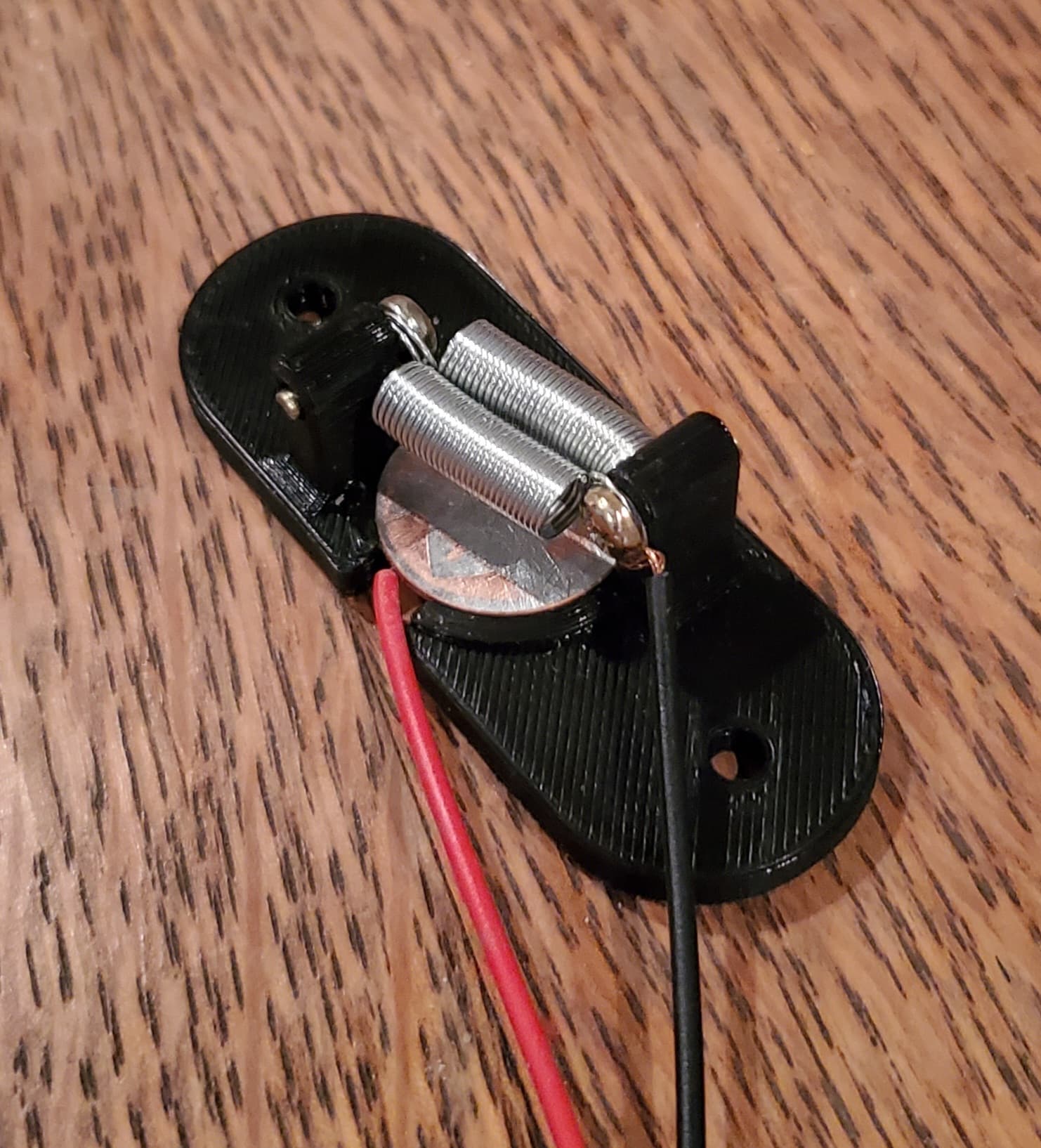
This mechanism worked well for 1/8" bits, but, for flat-end 1/4" bits, the bit would occasionally catch the spring and push the spring to the plate. This is non-destructive, but indicates more design/experimentation is needed.
Here are the five scripts. Note the M500 (save settings command) in the bit change script. This allows a job to be restored after the electronics have been powered down. Also, the clearance height needs to be calculated based on the tallest bit you want to use with bit changes.
; Home XY in machine space
G53          ; Machine coordinates
G28 X Y      ; Home XY
G54          ; Workspace coordinates
; eof

; Home Z in machine space
; Movement over the bitsetter is controlled
;   in firmware by Z_SAFE_HOMING settings
G53          ; Machine coordinates
G28 Z        ; Home Z
G0 Z35 F480  ; Move to clearance height
G54          ; Workspace coordinates
; eof

; Touch Plate Probe
G38.2 Z-250 ; Downward probe with a destination never reached
G92 Z0.5    ; Account for the plate thickness
G0 Z2 F480  ; Move up to remove the probe
M0 S2       ; 2 second pause to remove the touch plate
G0 Z0       ; Return to Z=0
; eof

; Bit change
G53
G0 Z35 F480      ; Move to clearance height
G0 X200 Y3 F2000 ; Move to bit change location
M500             ; Save the workspace offset
;eof

; Restore to job origin
G53            ; Machine coordinates
G0 X5 Y5 F2000 ; Speed things up by a rapid move to near the bitsetter
G28 Z          ; Home Z
G0 Z35 F480    ; Move to clearance height
G54            ; Workspace coordinates
G0 X0 Y0 F2000 ; Go to stock origin XY
G0 Z0 F480     ; Optional.  Use only if Z=0 is always safe
; eof
The process:
- Run Home XY script
- Run Home Z script
- Set up the job origin relative to the stock. If a touch plate is used, G38.2 must be used instead of G28.
[Then for each bit change]
- Run Change Bit script
- Change the bit in the router
- Run Home XY script (only needed if the steppers are released or the electronics have been power cycled).
- Run Restore job script
As mentioned above, probing must be used instead of homing for the touch plate. The following are the lines I changed in Marlin to enable probing for the Rambo Primo version of the firmware:
In configuration_adv.h, I uncommented this line
#define G38_PROBE_TARGET
In configuration.h, I uncommented these lines:
#define FIX_MOUNTED_PROBE

#define MULTIPLE_PROBING 2

#define Z_SAFE_HOMING
In addition, the following two values should be set to the X and Y position of where the bitsetter is mounted. In my case it was the origin of the machine:
#define Z_SAFE_HOMING_X_POINT 0  // X point for Z homing
#define Z_SAFE_HOMING_Y_POINT 0  // Y point for Z homing
Eventually, I plan to add the five scripts to my pendant, but currently I put them in the V1 custom menu in the order I use them.
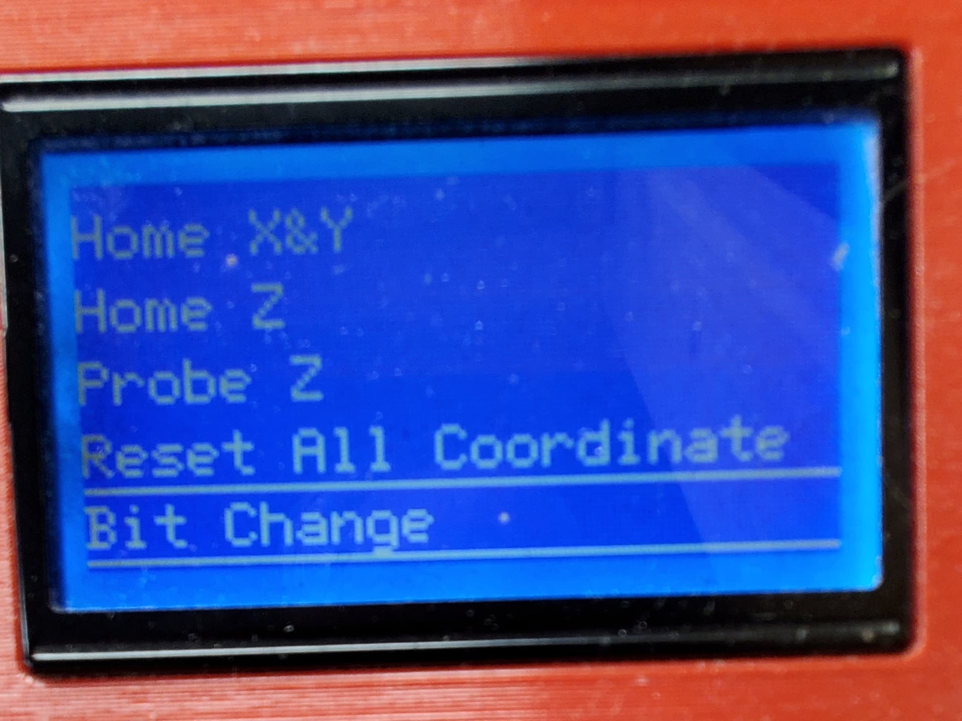
There was a simpler process I’ve considered. If I plan on always either releasing the steppers or turning off the electronics, then I would only need three scripts. XY & Z could all be homed at the same time, and the bit change script would be eliminated. I would add the M500 to the Reset All Coordinates script. This would have the side benefit of allowing the same job to be rerun if a power failure occurred.