Mac how do you insert the MPCNC.cps?
The properties window changes from Mac to Windows
Thank you for the offer!
I’ll spend some time with it over the weekend and post something.
Is here anyway to get fusion to start milling at a chosen corner of a work piece? I tried to move the origin of my tool in fusion but repeter host still shows the machine starting in the middle of the workpiece.
Under the Links tab of the 2D Contour and 2D Pocket operations dialogs there’s an item named “Entry Positions” in the Positions sub-menu. This item allows you to specify a start position for any of the geometry chains in the operation. Give that a try. I think it will do what you want.
If you want to post your .f3d file or the gcode file I can take a look at it. If you’re using the MPCNC post processor posted here then it sets 0,0,0 to be at the location of the tool when the gcode is executed.
I’m running the V6 MPCNC post processor. Ill send a link of the Fusion file. I know its a mess and I’m learning fusion. Just trying to print 1 sidestep.
I don’t see anything wrong wth the Fusion 360 file. It is conventional milling instead of climb milling though With regards to the Repeatier host it may be that you need to define a “printer” that has its origin at the same place as your MPCNC
I can not understand why even if I copy the file to the .cps Funsion360-CAM Data folder can not find it in the list of Posts (in Windows 7)
Can you help me ?
In MAC OS it works fine
Thanks
ManuCNC,
I have only used windows 8 and 10. You should be able to put your post processor file anywhere -> Open the Post Process dialog and specify the folder’s path by selecting the … box under Configuration Folder. Then select your .cps file in the Post Configuration menu. You are getting an empty list? Try using another folder for the fun of it.
I just keep my custom MPCNC posts in a folder with all my MPCNC design folders.
Hello everyone,
I’m having issues with my test cuts. I’m using the post processor I found on this site, which seems to work well with the exception of the z-axis. Whenever the z position drops below zero (essentially to start cutting) the motor stops working. The repetier software shows that the router made the movement but it doesn’t actually happen. If the movements are above zero it will work fine. I don’t know if its a repetier problem or a gcode problem. Does anyone have any ideas on what my problem is?
-Charles
Charles,
That’s strange. Any Z axis lockout should have nothing to do with the post processor. What Marlin firmware are you using? Is there a Z < 0 lockout enabled somewhere in configuration.h? I will take a look. Everything - Marlin, Fusion 360 and the post processor have been working fine for me and I have not looked at the firmware since last fall. I’m a bit rusty on it now.
As a test can you just give it some simple hand edited gcode to move the three axes below zero? http://reprap.org/wiki/G-code
I use a full graphics LCD/SD card and have not used Repetier in a long time. Is there a mode in Repetier to lock out axis like this?
-Steve
Charles,
How about looking at configuration.h in your Marlin version. Around line 360 is this define:
#define min_software_endstops false // If true, axis won't move to coordinates less than HOME_POS.
If this is set to true it won’t drive the steppers to less than zero. Right?
-Steve
Also there is a red LED the turns on as soon as I start the cut. Is that something I should be worried about?
-Charles
Charles,
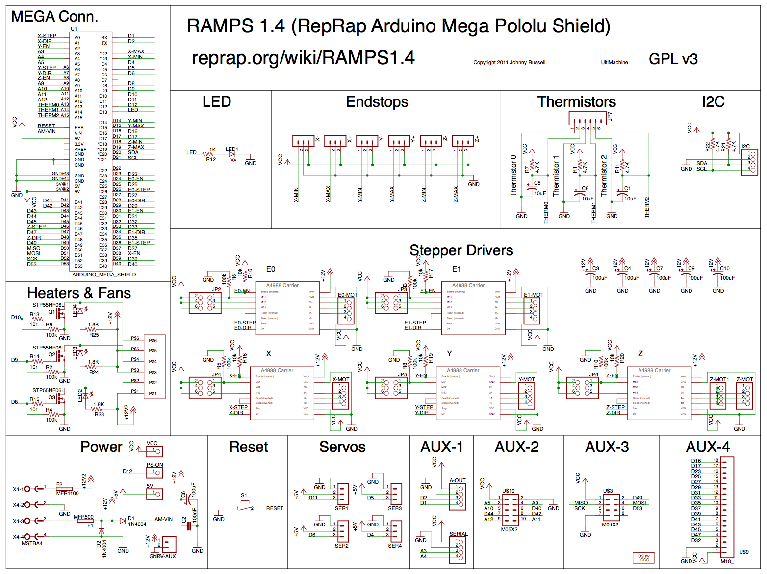
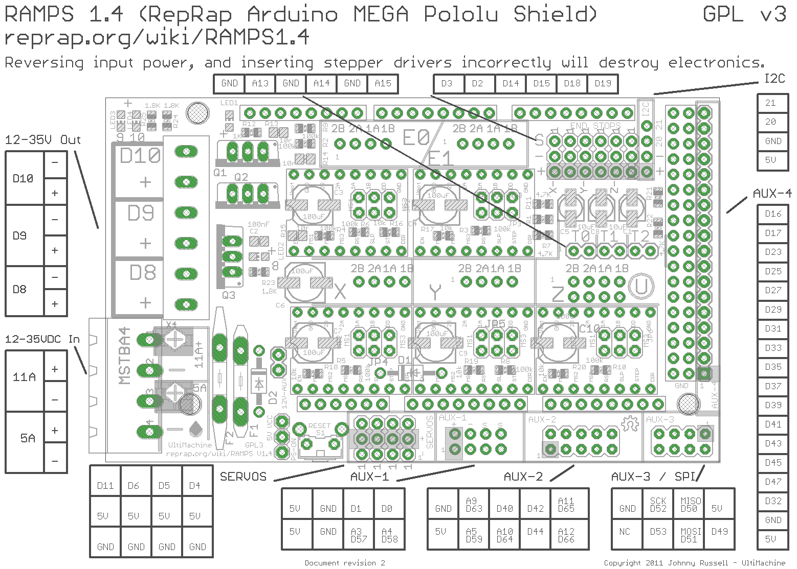
On mine the red LED3 on the RAMPS board here http://reprap.org/mediawiki/images/f/f6/RAMPS1.4schematic.png and here http://reprap.org/mediawiki/images/c/ca/Arduinomega1-4connectors.png turns on when I start to cut. That is just indicating that one of the power MOSFETs is being driven. Not sure why because those MOSFETs are normally unconnected and only used for a 3D printer configuration to power the heated bed and two plastic extruders. Probably just harmless vestigial 3D printer behavior.
Did you look at your configuration.h file? That is likely the problem.
-Steve
Hi everyone,
I am using Inventor HSM 2016, which is supposed to run the same CAM system as Fusion 360 with the only difference being that it might have a few more features. I tried running my first test part with the MPCNC_Fusion360_V6_SDcard.cps file found on page 2. My test part is kind of small at around an inch by two inches with a few different sized holes in the center, and different fillet radi around the outside. HSM shows an estimated run time of 1min 16sec which seems right with the feedrates that I am using (35in/min about 15mm/s). But if I put it through repetier to double check it shows much shorter times. When I go to run the machine it seems like the x axis works, but the x and y just kind of do nothing or move very little.
What settings do you guys use for feeds and speeds? I know plunge rate is basically how fast the z axis will lower, but what one controls how fast it comes out?
Edit:
Downloaded Fusion 360 and followed a post someone put on their blog about using it. Just imported my part from inventor. Everything worked just fine. I think the z speed was a bit fast for my MPCNC, but that is easy to slow down.
I wonder if the issue with inventor was the units. Everything else seemed exactly the same as in fusion.
The post above is too old to edit, so I guess I will double post.
Using Inventor HSM 2016 I changed the document units to mm and re did all of CAM stuff. The V6 LCD post processor worked great!
HSM in inventor looks to be exactly the same as the CAM in Fusion 360. This means anyone running Solidworks should theoretically be able to use the same exact post processor and HSMexpress. Keep in mind, HSMexpress (cam for solidworks) only goes to 2.5D CAM. No full 3D milling or any turning as far as I know. I have both Inventor and Solidworks, so I will test this theory soon.
About units in mm
(First,I am a beginner, and thank you so much for “MPCNC_Fusion360_V6_SDcard.rar”)
I am looking at my gcode and see this:
;square cut
;T2 D=3.175 CR=0 - ZMIN=-16 - flat end mill
N10 G90
N15 ;Units in mm
N20 G92 X0 Y0 Z0
N25 M84 S1800 ;Change Stepper disable timeout to 30 minutes
N30 G1 Z10 F2000 ; Lift Z 10mm to avoid dragging to first operation
In block N15 it just says “;Units in mm”. There is no G20 or G21. Does Marlin default to mm, or am I supposed to add that in ? I am using mm in Fusion 360.
Thank you in advance, especially if it’s a dumb question.
Bill
William,
I just got back from a 2 week vacation and my brain is a bit fried but I think that everything in Marlin defaults to mm. I don’t think that I made any changes to the configuration.h or post file for mm.
Let us know how it works out.
Steve


