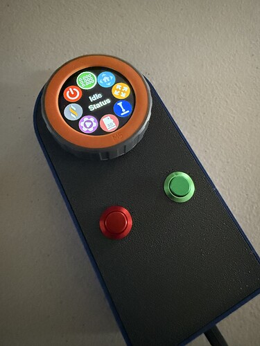
That is so clean.
Good morning, Doug.
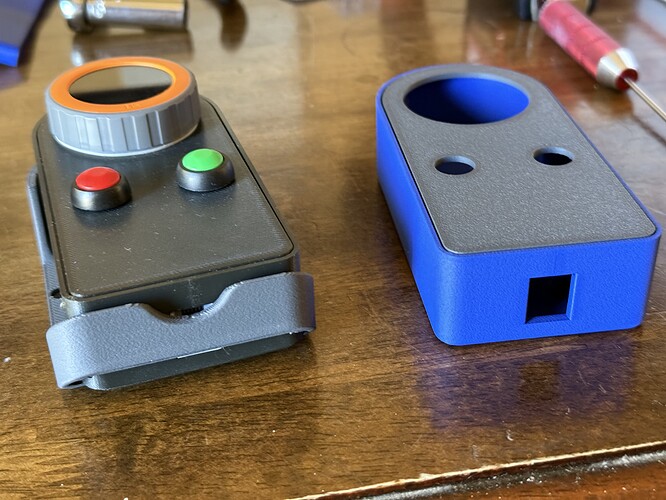
I’ve printed the cradle for the LR4 and realized there is no cutout to allow room for the control cable… Am I missing something, or did I print the wrong file?
I am going to have to make an edit to help with that.
If you have a Dremel tool, or something that can cut a little notch into it, you can modify it to serve without having to re-print it. So sorry for the oversight.
Thank you, Sir! Happy Sunday!
Your contributions are amazing.
Sharp looking pendants!!
Thanks Doug! Now I just need to figure out how to get it to connect to the jackpot board.
Just starting out so I will use the Web UI at first, but I’d like to have the pendant functioning so it’s a viable option.
So, assuming you’re using Bart’s starter kit, and that you have the 6-pin cord that Bart recommends for it, then one PCB plugs into the Jackpot, and the other goes into the pendant. Also assuming you have installed the firmware onto the M5Dial as shown in the wiki…
Then, finally you’ll need to modify your config.YAML file as shown in the wiki, but with a key difference to the GPIO numbers for transmit and receive. I explain the GPIO edits in my build thread here: Fluid Dial (Fluid NC dial pendant by Bart Dring, using M5 Stack's M5 Dial) - #9 by DougJoseph
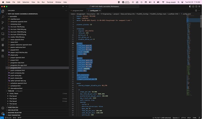
Just to be clear, you quoted only a part of the full config.yaml settings that are needed. If using Bart’s kit- the full set looks like this:
Yep, and in my original posting, I had missed my mistake on that until it was too late to edit the post. In my “quote” of it above, in the last image, I replaced the original image with a revised one that has the red square extended to surround the last bit of code I had failed to highlight in the original post.
Thanks for making sure to call attention to the full code snippet!
Here’s a screen shot (in Visual Studio code) of my config.YAML file, and a copy and paste of the code. I think it’s identical to what @MakerJim shared above, down to the last letter.
uart2:
  txd_pin: gpio.14
  rxd_pin: gpio.13
  rts_pin: NO_PIN
  cts_pin: NO_PIN
  baud: 1000000
  mode: 8N1

uart_channel2:
  uart_num: 2
  report_interval_ms: 75
GM, Doug.
Can you share a link to that wiki?
Ty
@Michael_Melancon beat me to it. Also, I’m pretty sure it’s linked from my build log too.
Doug, what magnets did you get?
Can I download the config file from the Jackpot, modify the lines of code, and then upload back to the jackpot all using the webUI and wifi?
Yes you can.
After upload, you will just need to restart the board.
thank you Mike!
on it!
my gut is saying “make a copy of the config.yaml file and rename it (OLD) so that I have a backup in case I FIUBAR”…then I’ll have a way to recover ![]()


