Thanks @DougJoseph another quick question. Are your leds always on or only on when pressed?
They are always on, whenever the CNC / Pendant are on.
So basically you have 3 wires coming out of the + of the “dring” board in the pendant
1 for each button and 1 for the dial…same with the negative.
If i wanted to have the led on only when pressed, i can have the same 3 for the negative but bridge the positive to either switch post of the button, then the led only should get power when pushed
The LED leads have a + and - on them on the “inside” / back of the button. The switch leads do not have that.
Yes, exactly. three of the + and three of the -. One each to the buttons and one to the dial, of both + and -.
Two things here. 1. The color of the LED should ideally be lit up and visible so the user knows which is green button and which is red. 2. When it is pressed down, your finger is on it, covering up the light, so if it’s only lit up then, you would not be getting any good from it.
LEDs don’t wear/degrade the way you might think. Although they may be “30V compatible”, that means they don’t burn out and die instantly at 30V. It doesn’t mean that they won’t degrade and eventually burn out.
They may have degraded significantly since you started using them.
1 Like
If someone finds thier LEDs “Bright and really hot”, there’s an option to install a series current limiting resistor. If someone finds that situation they should reach out and get some EE guidance on what values to try.
2 Likes
Thanks!
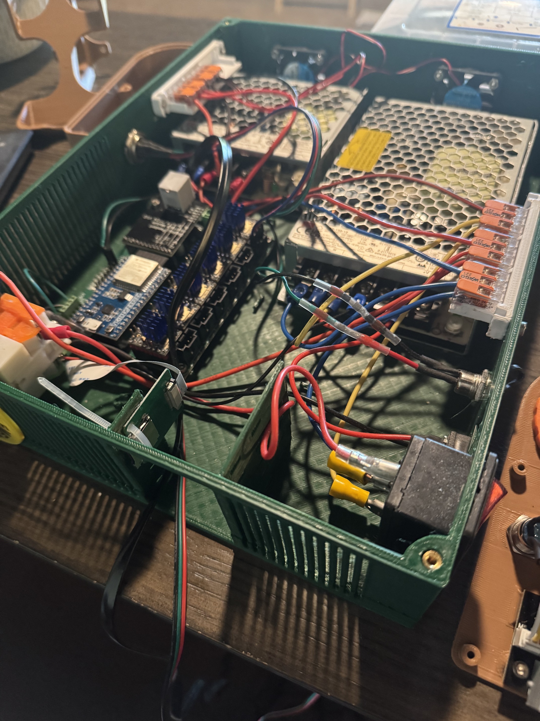
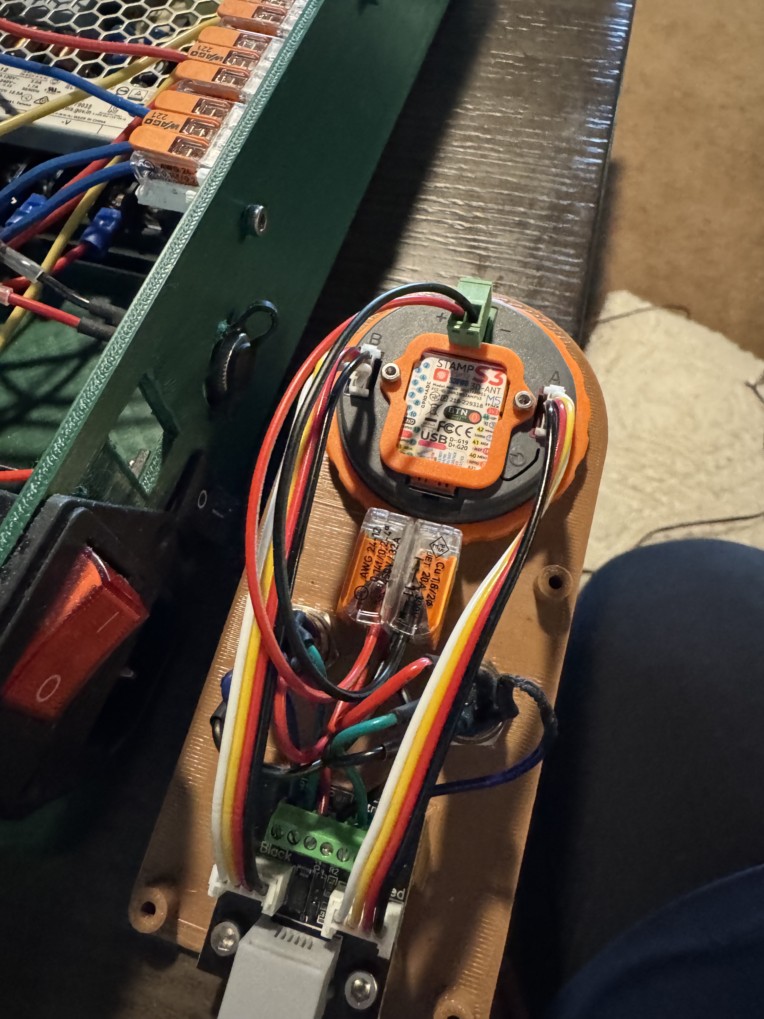
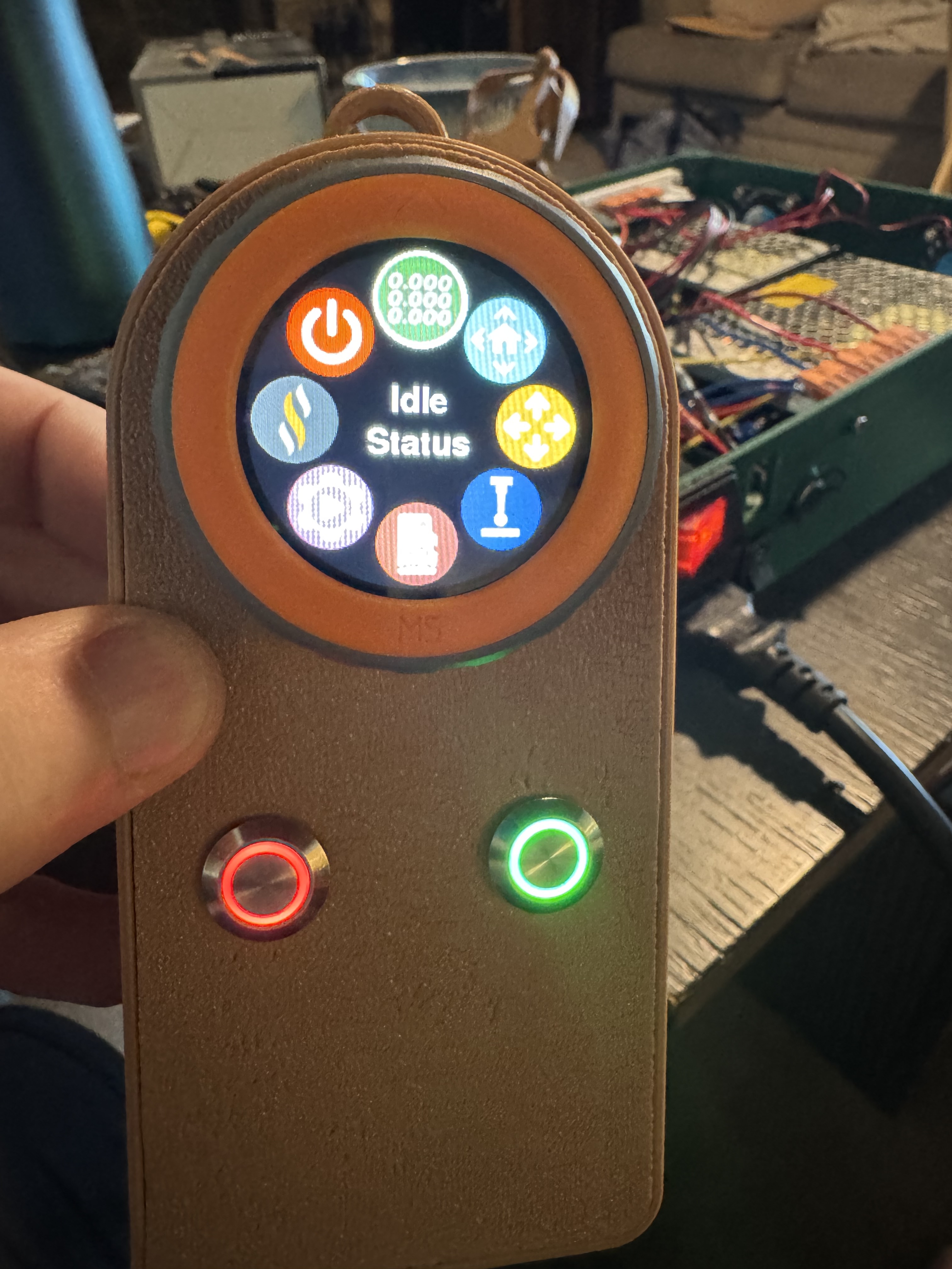
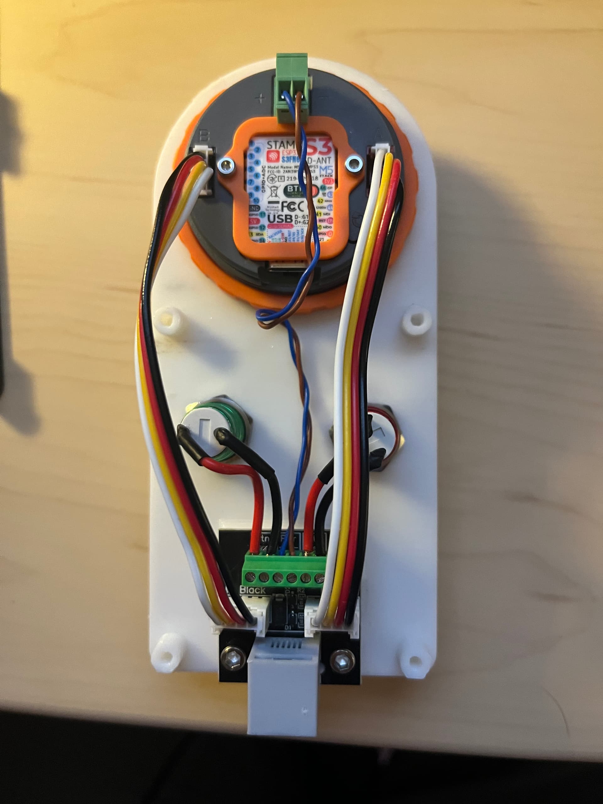
@DougJoseph and @MakerJim thanks for all the help. I think my control box is done and the pendant seems to connect fine. Since my soldering skills are pretty bad I glued 2 wago connectors below the dial for the 3 + and - connections to make it easier to replace the buttons if needed
5 Likes
Great work! I can’t wait to see details of your machine moving with this setup.
3 Likes
Awesome! Your pendant is connected and communicating so you must have done it right!!
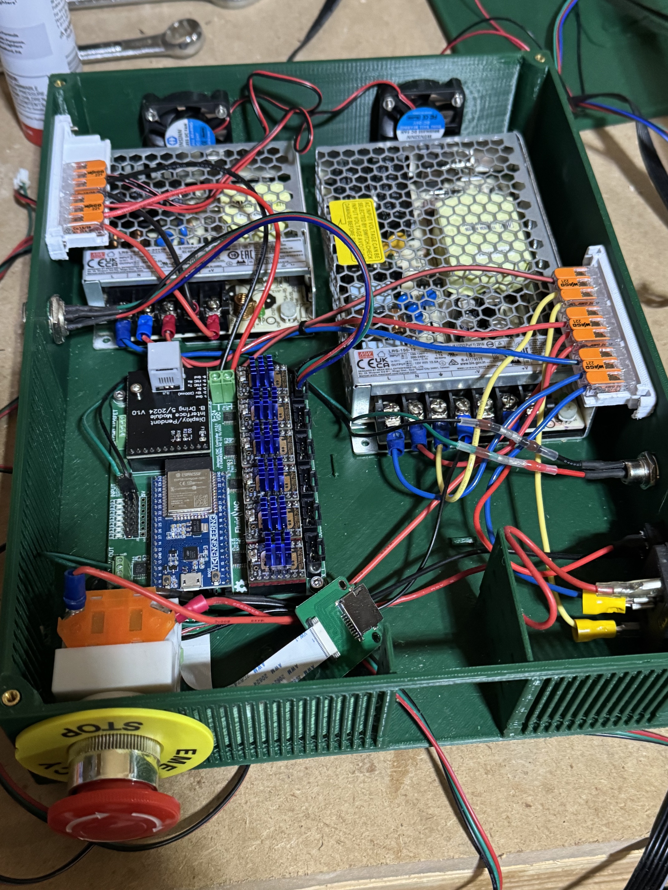
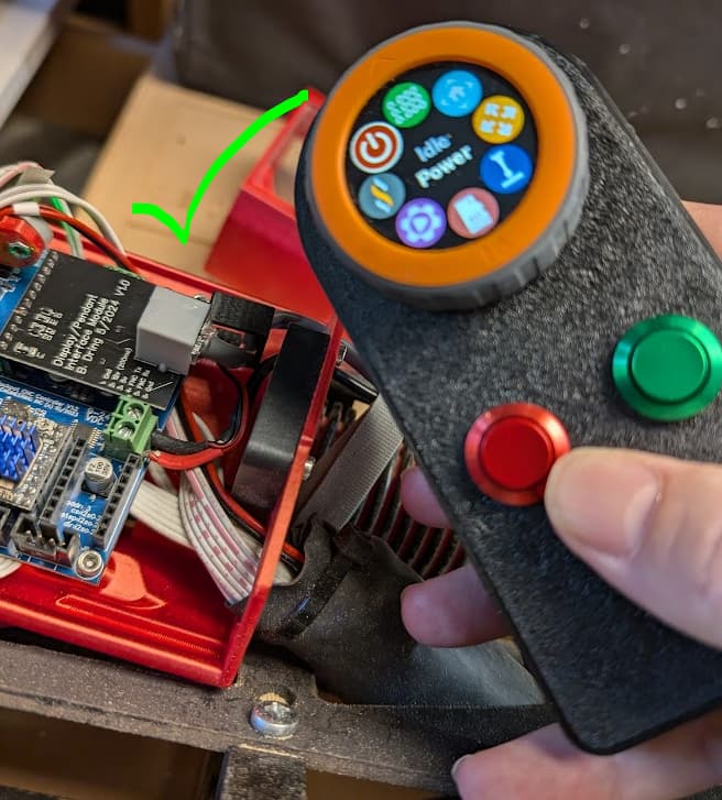
I hadn’t ran my pendant for a while (had kind of a flaky connection) so in celebration of LR4 “any day now” I grabbed Bart’s sweet new wiring module.
I had a few hiccups upgrading, do to some oversights on my part that I thought I’d document here, in case any future denizen of V1E searches for it on a whim.
- I compiled the FluidDial firmware a few months ago with no issue. But with the newest code (separate FluidDial github repo now) I had an issue compiling (could not find FreeRTOS.h) which I had to resolve by manually deleting 2 similarly-named
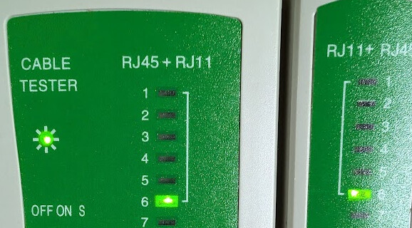
C:\Users\<username>\.platformio\packages\framework-arduinoespressif32\directories. Then it built and filesystem uploaded just fine. Weird. - Got an RJ11/12 cable crimper and made the cable from cat5e cable, just snipped off the extra pair. Indispensible is a network cable tester that tests all of the pins one-by-one (was happy to notice it has a 6-pin RJ11 testing port)
- Updated the firmware (web updater) on my Jackpot to 3.8.3, but initially forgot to grab the new stuff from GitHub - V1EngineeringInc/FluidNC_Configs: Configuration and support files for the FluidNC boards typically used and V1 Engineering which has changed quite a bit since when I first upgraded to the version 3 web UI.
- The behavior of note with new firmware/ old config (but the right TX and RX pins + baudrate for uart2 in the config.yaml) was that the FluidDial was restarting over and over. I believe this was because the Jackpot was probably restarting over and over. Once I had the right config files uploaded, everything worked great.
- So, short version of the above:
- Weird FreeRTOS.h build issue → delete the .platformio/packages/*espressif-32 directory to build.
- Cable tester definitely worth its weight in gold for those home-crimped network cables, one less thing to troubleshoot
- Backup config.yaml then fully-wiped the Jackpot via the FluidNC web installer to 3.8.3, and then uploaded the files at GitHub - V1EngineeringInc/FluidNC_Configs: Configuration and support files for the FluidNC boards typically used and V1 Engineering + additions to config.yaml (I’ll restore my calibration settings later)
uart2:
  txd_pin: gpio.14
  rxd_pin: gpio.13
  rts_pin: NO_PIN
  cts_pin: NO_PIN
  baud: 1000000
  mode: 8N1

uart_channel2:
  report_interval_ms: 75
  uart_num: 2
Victory! Weird connection issues have vanished. Ready for the LR4!
Thanks @design8studio for the case and standoff thingy!
3 Likes
Love the red and green anodized buttons. Would you mind sharing a link to them?
Thanks!
2 Likes
I used those same buttons, and they were an Amazon purchase set of buttons.
I have other uses for the silver and black buttons, and was only building 2 pendants initially- so it was perfect for me. And at $11 for the set, hard to go too wrong.
1 Like
Anodized red and green buttons makes it easier to build the pendant because you don’t have to worry about providing power to LED buttons.
The original plan from Bart called for printing red and green filled circles on paper, and gluing the paper to the printed lid.
My initial design replaced glued paper with printed red and printed green inserts, that got glued to the printed lid. That would allow knowing which is which without either anodized or LED colored buttons.
I went with these, but other linked ones are definitely cheaper!
APIELE 16mm Momentary Push Button Switch
Of note, for these specific buttons, had to enlarge the holes on Doug’s enclosure to 16.5 mm (used negative cylinders in orcaslicer, pretty easy)
1 Like
Hmm. The set of 8 for only $11, that @MakerJim linked, seems like a better deal — @coinbird am I seeing the price correctly on your link, at $7 for only one switch?
EDIT: I just also noticed, that the set of 8 linked by @MakerJim already have wires attached! That makes his linked set even more attractive!
I just printed Doug’s latest version that supports the RJ12 Bart adapter set. Worked flawlessly for me.
4 Likes
Yes, those look like a better deal for sure!
1 Like
Re. smaller buttons v larger buttons.
The spec from Bart was for smaller buttons, and I went that way too. They are almost too small. I could certainly see using larger ones as easier and better. But the smaller ones being more affordable is nice. And having wires already on them…