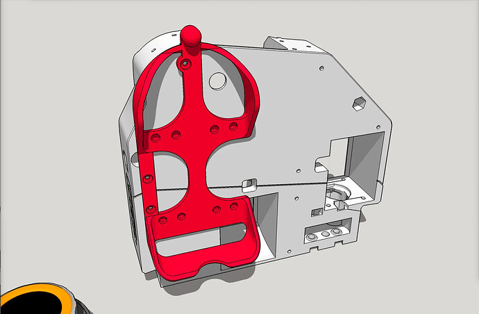
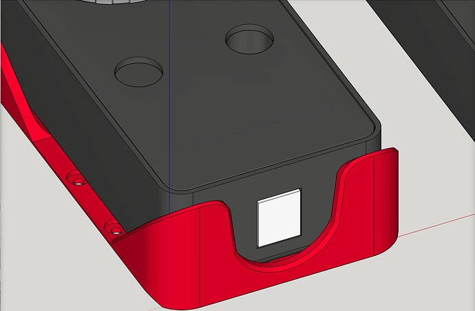
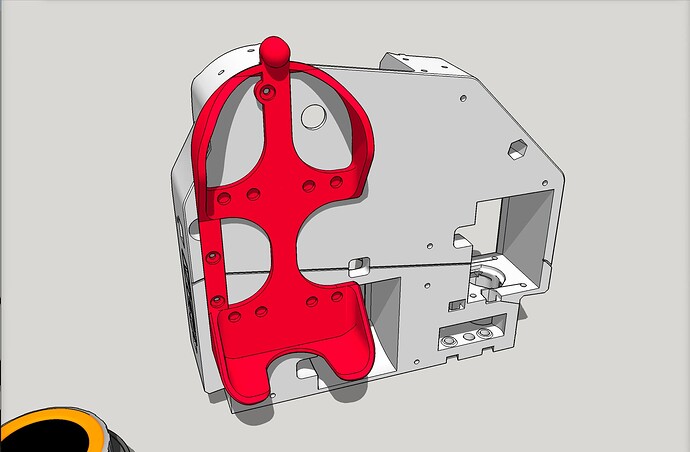
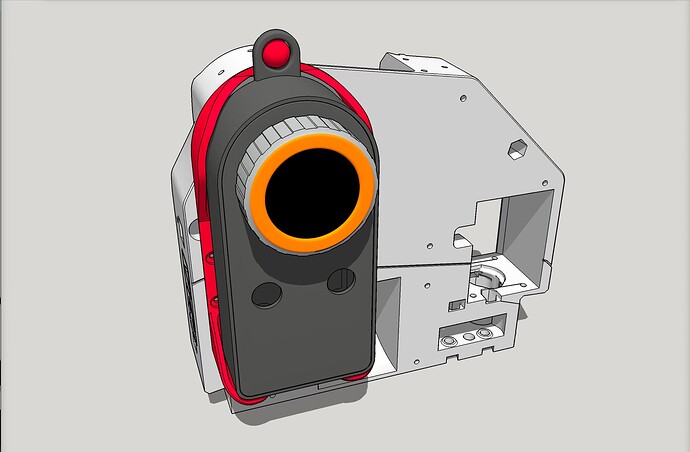
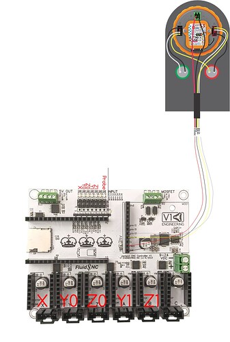
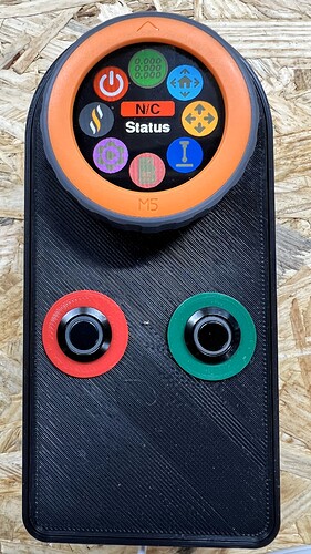
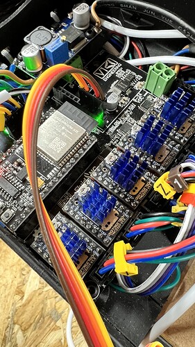
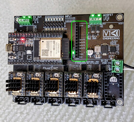
In the Printables listing for the cradle, I gave a link to what magnets I used. I think I also gave a link in the Printables listing for the case for the pendant.
So glad you got it working!!
LOL I forgot to print the cradle, so I never saw that listing. Thanks again
This is a good practice I think. I do this.
I have a folder on my laptop where I keep the backups, with the date in the file name.
Note: Oct. 23, 2024 — revised 2.2 cradle prints without need of supports (new as of this revision), and the notch on the bottom is deeper (it needed to be to accommodate the cord even when using Bart’s starter kit)
Awesome, Doug!
Thank You!!
Ok, So I’m trying to use the pendant strictly in on-location settings where a laptop is not practicle and I don’t want the students knowing they can connect via their phone (that’s asking for trouble!)
SO…Can someone explain to me, in the movement section, how to switch from a fast jog to micro movements. Both are necessary and I’ve stumbled on both but have no idea how I made it switch jog modes… what am i missing??? (probably reading something ![]() )
)
As always, Thanks!
Check here
I don’t have one, so I can’t say for sure…
But looks like you change the highlighted digit to control which number you are changing
" The left and right touch zones change the digit representing the jog amount. The digit will be highlighted in red. It represents the jog increment as well as the jog speed, which is proportional to the increment."
that’s exactly it! Thank you , Mike!!
I am struggling getting my M5 Dial pendant to talk to my Jackpot controller. My controller is working (all movement works from browser interface). I have checked my connection to the board (and checked continuity of connections). I have modified my Jackpot config.yaml code as suggested, using GPIO 14 and 13, but on powering on I get N/C instead of Idle.
Do I need to change anything in the FluidDial fimware prior to uploading? Are there any diagnostics/logs that I can check?
Do I need to modify the UART1 section of the FluidDial firmware to change the baud rate as per the wiki page -
FluidNC Config Example
You can use any 2 pins on the ESP32 that are UART capable (most are)
The default baud rate is 1000000. It can be changed in platformio.ini in this statement
-DFNC_BAUD=1000000
The config file Tx and Rx are with respect to the FluidNC. Be sure to connect the FluidNC Tx to the pendant’s Rx and the FluidNC Rx to the pendant’s Tx.
uart1:
  txd_pin: gpio.26
  rxd_pin: gpio.4
  rts_pin: NO_PIN
  cts_pin: NO_PIN
  baud: 1000000
  mode: 8N1

uart_channel1:
  report_interval_ms: 75
  uart_num: 1
board: Jackpot TMC2209
name: LowRider
meta: 03-15-2024 RyanZ
planner_blocks: 32

stepping:
  engine: I2S_STATIC
  idle_ms: 255
  pulse_us: 4
  dir_delay_us: 1
  disable_delay_us: 0

uart1:
  txd_pin: gpio.0
  rxd_pin: gpio.4
  rts_pin: NO_PIN
  baud: 115200
  mode: 8N1

uart2:
  txd_pin: gpio.14
  rxd_pin: gpio.13
  rts_pin: NO_PIN
  cts_pin: NO_PIN
  baud: 115200
  mode: 8N1

axes:
  shared_stepper_disable_pin: NO_PIN
  x:
    steps_per_mm: 50
    max_rate_mm_per_min: 9000
    acceleration_mm_per_sec2: 200
    max_travel_mm: 560
    soft_limits: false
    homing:
      cycle: 3
      positive_direction: false
      mpos_mm: 0
      feed_mm_per_min: 300
      seek_mm_per_min: 1500
      settle_ms: 500
      seek_scaler: 1.1
      feed_scaler: 1.1
    motor0:
      limit_neg_pin: gpio.25
      limit_pos_pin: NO_PIN
      limit_all_pin: NO_PIN
      hard_limits: false
      pulloff_mm: 4
      tmc_2209:
        uart_num: 1
        addr: 0
        cs_pin: NO_PIN
        r_sense_ohms: 0.11
        run_amps: 0.8
        homing_amps: 0.8
        hold_amps: 0.5
        microsteps: 8
        stallguard: 0
        stallguard_debug: false
        toff_disable: 0
        toff_stealthchop: 5
        toff_coolstep: 3
        run_mode: StealthChop
        homing_mode: StealthChop
        use_enable: false
        direction_pin: I2SO.1
        step_pin: I2SO.2
        disable_pin: I2SO.0
  y:
    steps_per_mm: 50
    max_rate_mm_per_min: 9000
    acceleration_mm_per_sec2: 200
    max_travel_mm: 1000
    soft_limits: false
    homing:
      cycle: 2
      positive_direction: false
      mpos_mm: 0
      feed_mm_per_min: 300
      seek_mm_per_min: 1500
      settle_ms: 500
      seek_scaler: 1.1
      feed_scaler: 1.1
    motor0:
      limit_neg_pin: gpio.33
      limit_pos_pin: NO_PIN
      limit_all_pin: NO_PIN
      hard_limits: false
      pulloff_mm: 4
      tmc_2209:
        uart_num: 1
        addr: 1
        cs_pin: NO_PIN
        r_sense_ohms: 0.11
        run_amps: 0.8
        homing_amps: 0.8
        hold_amps: 0.5
        microsteps: 8
        stallguard: 0
        stallguard_debug: false
        toff_disable: 0
        toff_stealthchop: 5
        toff_coolstep: 3
        run_mode: StealthChop
        homing_mode: StealthChop
        use_enable: false
        step_pin: I2SO.5
        direction_pin: I2SO.4
        disable_pin: I2SO.7
    motor1:
      limit_neg_pin: gpio.35
      limit_pos_pin: NO_PIN
      limit_all_pin: NO_PIN
      hard_limits: false
      pulloff_mm: 4
      tmc_2209:
        uart_num: 1
        addr: 3
        cs_pin: i2so.14
        r_sense_ohms: 0.11
        run_amps: 0.8
        homing_amps: 0.8
        hold_amps: 0.5
        microsteps: 8
        stallguard: 0
        stallguard_debug: false
        toff_disable: 0
        toff_stealthchop: 5
        toff_coolstep: 3
        run_mode: StealthChop
        homing_mode: StealthChop
        use_enable: false
        step_pin: I2SO.13
        direction_pin: I2SO.12
        disable_pin: I2SO.15
  z:
    steps_per_mm: 200
    max_rate_mm_per_min: 1200
    acceleration_mm_per_sec2: 80
    max_travel_mm: 300
    soft_limits: false
    homing:
      cycle: 1
      positive_direction: true
      mpos_mm: 0
      feed_mm_per_min: 300
      seek_mm_per_min: 800
      settle_ms: 500
      seek_scaler: 1.1
      feed_scaler: 1.1
    motor0:
      limit_neg_pin: NO_PIN
      limit_pos_pin: gpio.32
      limit_all_pin: NO_PIN
      hard_limits: false
      pulloff_mm: 4
      tmc_2209:
        uart_num: 1
        addr: 2
        cs_pin: NO_PIN
        r_sense_ohms: 0.11
        run_amps: 0.8
        homing_amps: 0.8
        hold_amps: 0.5
        microsteps: 8
        stallguard: 0
        stallguard_debug: false
        toff_disable: 0
        toff_stealthchop: 5
        toff_coolstep: 3
        run_mode: StealthChop
        homing_mode: StealthChop
        use_enable: false
        step_pin: I2SO.10
        direction_pin: I2SO.9
        disable_pin: I2SO.8
    motor1:
      limit_neg_pin: NO_PIN
      limit_pos_pin: gpio.34
      limit_all_pin: NO_PIN
      hard_limits: false
      pulloff_mm: 4
      tmc_2209:
        uart_num: 1
        addr: 3
        cs_pin: i2so.19
        r_sense_ohms: 0.11
        run_amps: 0.8
        homing_amps: 0.8
        hold_amps: 0.5
        microsteps: 8
        stallguard: 0
        stallguard_debug: false
        toff_disable: 0
        toff_stealthchop: 5
        toff_coolstep: 3
        run_mode: StealthChop
        homing_mode: StealthChop
        use_enable: false
        step_pin: I2SO.18
        direction_pin: I2SO.17
        disable_pin: I2SO.16

i2so:
  bck_pin: gpio.22
  data_pin: gpio.21
  ws_pin: gpio.17

spi:
  miso_pin: gpio.19
  mosi_pin: gpio.23
  sck_pin: gpio.18

sdcard:
  cs_pin: gpio.5
  card_detect_pin: NO_PIN
  frequency_hz: 20000000

probe:
  pin: gpio.36:low
  toolsetter_pin: NO_PIN
  check_mode_start: true

start:
  must_home: false

coolant:
  flood_pin: gpio.2
  mist_pin: gpio.16
  delay_ms: 0

control:
  safety_door_pin: NO_PIN
  reset_pin: NO_PIN
  feed_hold_pin: NO_PIN
  cycle_start_pin: NO_PIN
  macro0_pin: NO_PIN
  macro1_pin: NO_PIN
  macro2_pin: NO_PIN
  macro3_pin: NO_PIN

macros: {}

user_outputs:
  analog0_pin: NO_PIN
  analog1_pin: NO_PIN
  analog2_pin: NO_PIN
  analog3_pin: NO_PIN
  analog0_hz: 5000
  analog1_hz: 5000
  analog2_hz: 5000
  analog3_hz: 5000
  digital0_pin: gpio.26
  digital1_pin: gpio.27
  digital2_pin: NO_PIN
  digital3_pin: NO_PIN
Those are the wrong settings for a Jackpot board using the default wiring (Or a Bart version of the RJ12 adapter set.)
For a jackpot board the config.yaml should have this in it:
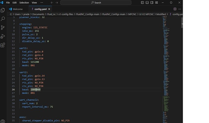
uart2:
  txd_pin: gpio.14
  rxd_pin: gpio.13
  rts_pin: NO_PIN
  cts_pin: NO_PIN
  baud: 1000000
  mode: 8N1

uart_channel2:
  uart_num: 2
  report_interval_ms: 75
Those are the correct settings for the way the Jackpot board expansion connecter is laid out.
The reference to GPIO.26 & .4 were just a quote from the wiki. The text below was a copy of my config.yaml, which I had changed as per Doug’s instructions at the start of this topic, but I hadn’t included the section for uart_channel2:
This has now sorted it. Many thanks Jim
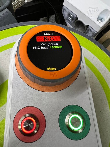
I am not able to get my fluid dial working it shows NC and
I’ve wired it according to Doug’s instructions and configured the .yaml file as per Maker Jim’s information:
here is the error message I get when booting FluidNC:
[MSG:INFO: FluidNC v3.9.1 GitHub - bdring/FluidNC: The next generation of motion control firmware]
[MSG:INFO: Compiled with ESP32 SDK:v4.4.7-dirty]
[MSG:INFO: Local filesystem type is littlefs]
[MSG:INFO: Configuration file:config.yaml]
[MSG:ERR: Ignored key uart2]
[MSG:INFO: Machine MPCNC]
[MSG:INFO: Board Jackpot TMC2209]
[MSG:INFO: UART1 Tx:gpio.14 Rx:gpio.13 RTS:NO_PIN Baud:1000000]
[MSG:ERR: UartChannel: missing uart2]
Then there is an error in your config.yaml - indents and formatting are critical in yaml even an extra space will cause an error.
Post your yaml here (in a code block) and let’s see if there’s anything obvious.
Yes Indeed syntax matters I corrected it and got past the errors when booting FluidNC…but the pendant still still shows NC not connected:
here is the verbose txt when starting fluidNC there are no errors and I see that the UART 2 channel was created:
$G
$SS
[MSG:INFO: FluidNC v3.9.1 GitHub - bdring/FluidNC: The next generation of motion control firmware]
[MSG:INFO: Compiled with ESP32 SDK:v4.4.7-dirty]
[MSG:INFO: Local filesystem type is littlefs]
[MSG:INFO: Configuration file:config.yaml]
[MSG:INFO: Machine MPCNC]
[MSG:INFO: Board Jackpot TMC2209]
[MSG:INFO: UART1 Tx:gpio.0 Rx:gpio.4 RTS:NO_PIN Baud:115200]
[MSG:INFO: UART2 Tx:gpio.14 Rx:gpio.13 RTS:NO_PIN Baud:1000000]
[MSG:INFO: uart_channel2 created at report interval: 75]
[MSG:INFO: I2SO BCK:gpio.22 WS:gpio.17 DATA:gpio.21]
[MSG:INFO: SPI SCK:gpio.18 MOSI:gpio.23 MISO:gpio.19]
[MSG:INFO: SD Card cs_pin:gpio.5 detect:NO_PIN freq:20000000]
[MSG:INFO: Stepping:I2S_STATIC Pulse:2us Dsbl Delay:0us Dir Delay:1us Idle Delay:255ms]
[MSG:INFO: User Digital Output: 0 on Pin:gpio.26]
[MSG:INFO: User Digital Output: 1 on Pin:gpio.27]
[MSG:INFO: Axis count 3]
[MSG:INFO: Axis X (3.000,1223.000)]
[MSG:INFO: Motor0]
[MSG:INFO: tmc_2209 UART1 Addr:0 CS:NO_PIN Step:I2SO.2 Dir:I2SO.1 Disable:I2SO.0 R:0.110]
[MSG:INFO: X Neg Limit gpio.25]
[MSG:INFO: Motor1]
[MSG:INFO: tmc_2209 UART1 Addr:3 CS:I2SO.14 Step:I2SO.13 Dir:I2SO.12 Disable:I2SO.15 R:0.110]
[MSG:INFO: X2 Neg Limit gpio.35]
[MSG:INFO: Axis Y (3.000,2443.000)]
[MSG:INFO: Motor0]
[MSG:INFO: tmc_2209 UART1 Addr:1 CS:NO_PIN Step:I2SO.5 Dir:I2SO.4 Disable:I2SO.7 R:0.110]
[MSG:INFO: Y Neg Limit gpio.33]
[MSG:INFO: Motor1]
[MSG:INFO: tmc_2209 UART1 Addr:3 CS:I2SO.19 Step:I2SO.18 Dir:I2SO.17 Disable:I2SO.16 R:0.110]
[MSG:INFO: Y2 Neg Limit gpio.34]
[MSG:INFO: Axis Z (-100.000,200.000)]
[MSG:INFO: Motor0]
[MSG:INFO: tmc_2209 UART1 Addr:2 CS:NO_PIN Step:I2SO.10 Dir:I2SO.9 Disable:I2SO.8 R:0.110]
[MSG:INFO: Z Neg Limit gpio.32:low]
[MSG:INFO: X Axis driver test passed]
[MSG:INFO: X2 Axis driver test passed]
[MSG:INFO: Y Axis driver test passed]
[MSG:INFO: Y2 Axis driver test passed]
[MSG:INFO: Z Axis driver test passed]
[MSG:INFO: Kinematic system: Cartesian]
[MSG:INFO: STA SSID is not set]
[MSG:INFO: AP SSID FluidNC IP 192.168.0.1 mask 255.255.255.0 channel 1]
[MSG:INFO: AP started]
[MSG:INFO: WiFi on]
[MSG:INFO: Captive Portal Started]
[MSG:INFO: HTTP started on port 80]
[MSG:INFO: Telnet started on port 23]
[MSG:INFO: Flood coolant gpio.2]
[MSG:INFO: Mist coolant gpio.16]
[MSG:INFO: Probe gpio.36:low]
ok
FluidNC Dial is still NC not connected:
I’ve just gone through the same pain, which turned out to be incorrect UART2 setting in config.yaml. Yours seems to look ok. Make sure you have the wiring of the Tx and Rx crossed between the Jackpot and the Pendant i.e. Tx - Jackpot to Rx - Pendant, Rx - Jackpot to Tx - Pendant.
