Recently in another thread I intimated that I had started playing with laser inlays once again and, after a few rather frustrating days, I think I have come upon a good way to produce inlays that are accurately fit and quick to do.
I realize not everyone has Lightburn and a fairly powerful laser engraver. But hopefully, with the introduction of the new stacked diode lasers putting out 20W optical power, or more, and starting at under $1000, many may see something here that will “push you over the edge”. Lightburn software is also “not free” but is “reasonable”… and has rapidly become the “standard” for folks working with lasers.
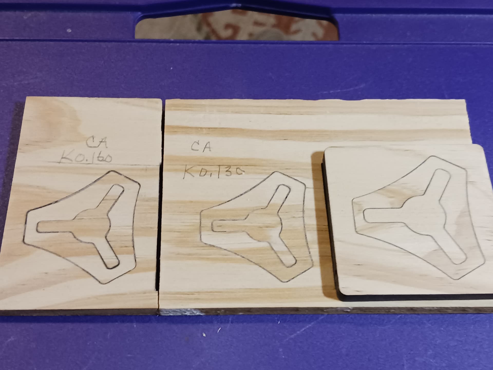
The method I’m showing here comes after some days of frustration trying to use the kerf offset settings in Lightburn to make nice fitting inlays. Indeed, using that method, I came up with a few reasonably nice-looking inlays…
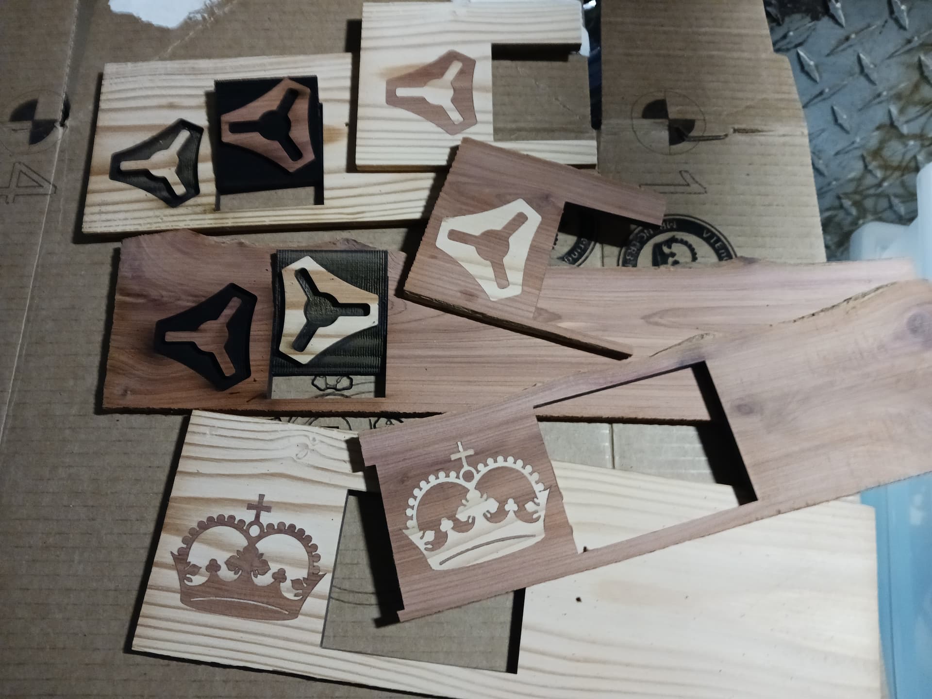
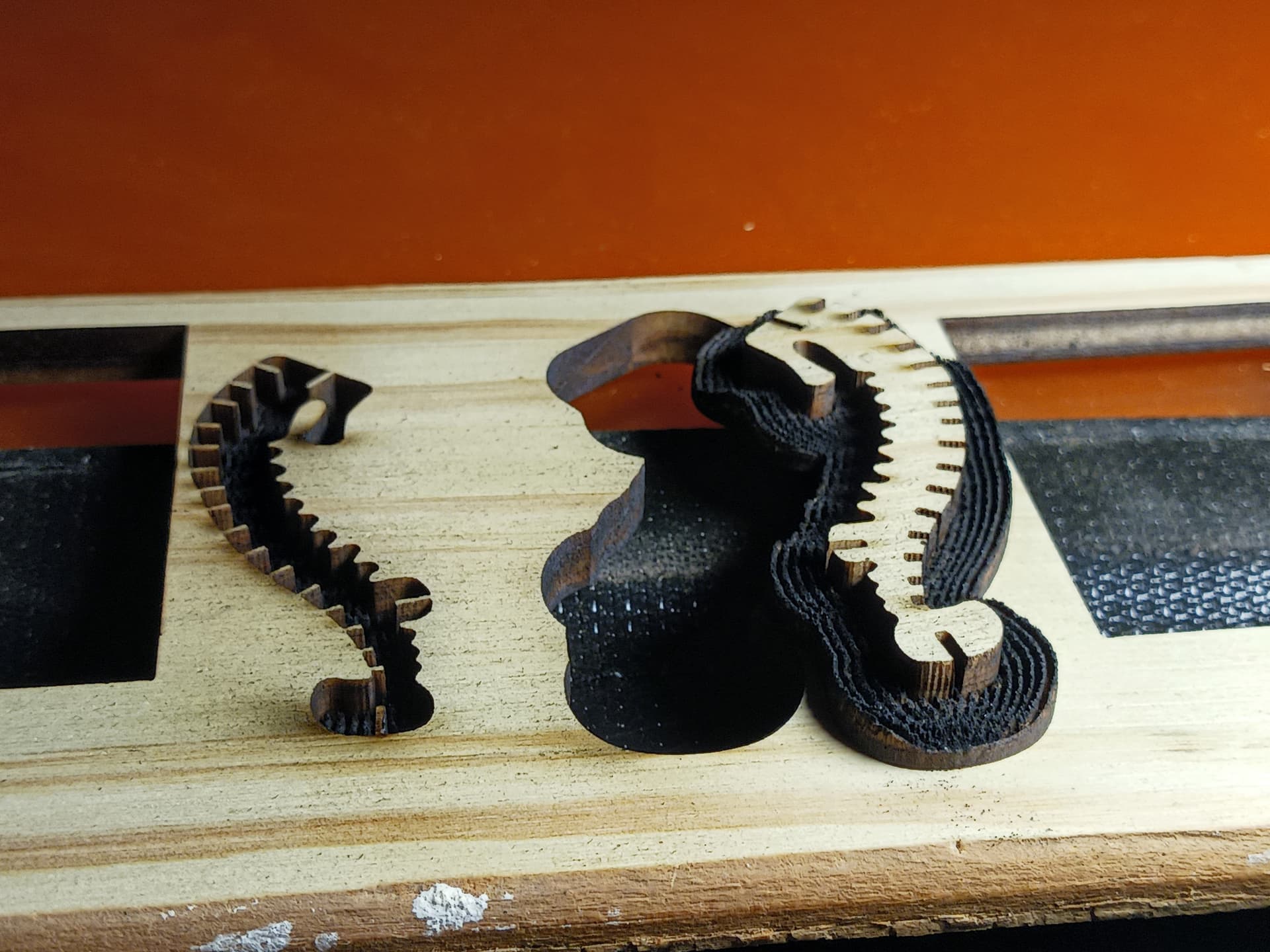
Others, with more detail, not so much…
Missing pieces, not so clean, and muddy, non-uniform glue lines.
So, I revisited my kerf calculations and found a similar but easier-to-use kerf program…
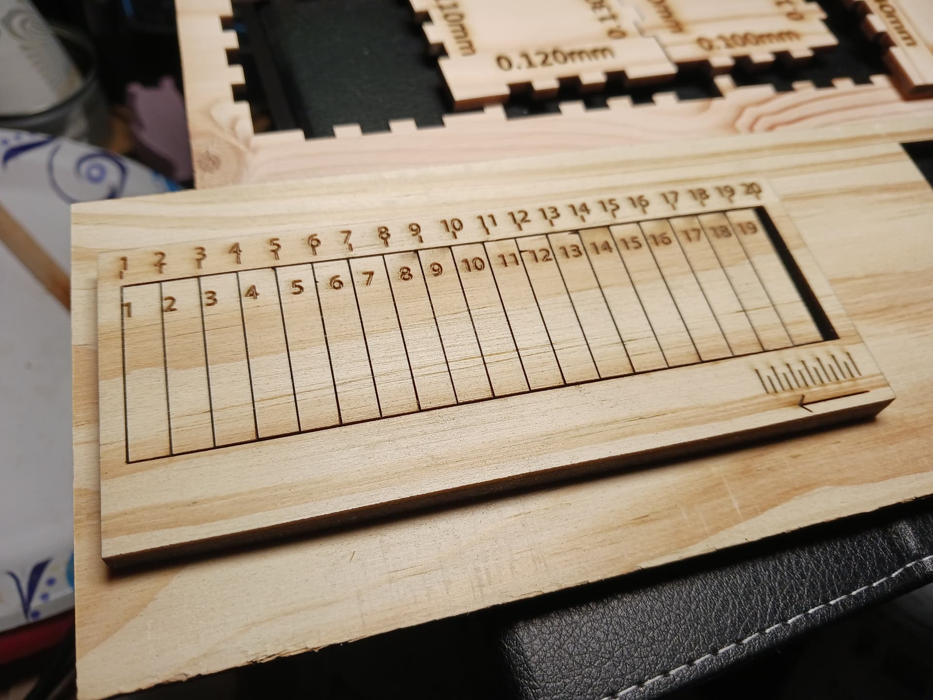
19 segments, 20 nodes. Push them all to one end and measure the end gap with digital calipers. I got 3.37mm gap, divided by 20, and came up with 0.169. Half that for kerf offset in Lightburn. However, using kerf, normally for outside shapes it’s outward, for inside shapes it’s inward. And when you start playing with inlays, you may have many inside and outside shapes in a detailed piece. It’s confusing and changes depending on how much detail is in the inlay… and I kept getting worse and worse results.
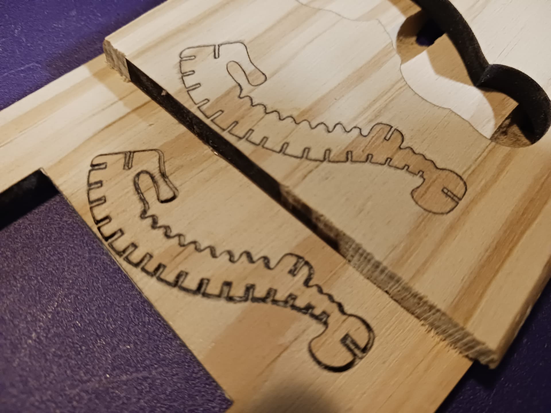
So, then I started playing with the Offset tool in Lightburn. Take a simple shape in outline mode and Offset it, BOTH inward and outward… like a 2-lane highway centerline to adjacent lane edgelines on either side. The offset value I used was 0.08… about half of the 0.169 above. That left me with double lines, one-half a kerf width on either side of the original lines.
From, there I selected all the inward edges and put them on the “pocket” layer. All the outward edges, move to the “inlay layer” and, while still selected, move them to the right.
Side-by-side, you now have two images, "pocket’ on the left, “inlay” on the right… differing in size by one full kerf-width. The left image, “pocket”, is essentially done. Also, pay particular attention to what’s selected when finishing an Offset operation.… most often it’s exactly what’s needed for the next operation and saves confusion should you click elsewhere and deselect it.
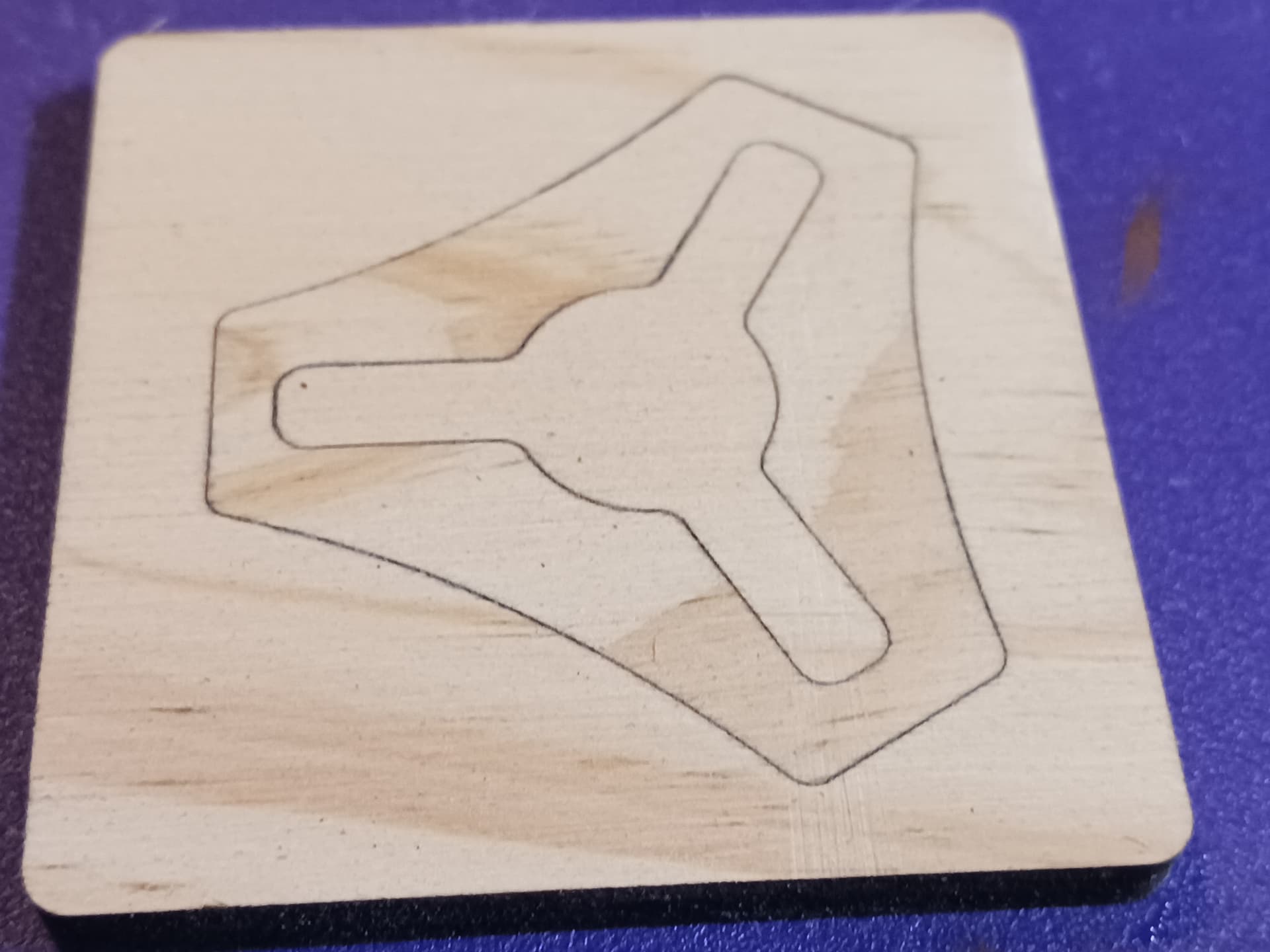
The right image, still selected from the move to the right, needs to be mirrored horizontally, and using the Offset tool once again, create a 5mm or so clearance area, around the actual inlay, which will remove any material that will prevent the inlay and pocket from joining together. Still selected, I create another Offset 1mm outward and then put it onto a third layer, the “inlay_profile” layer, with power and speed settings sufficient to cut completely through the material. This profile cutline is still 1mm proud of the clearance edge, so move it back with the Offset tool once again… inward 1mm to coincide with the edge of the clearance area.

This actually completes the process of creating side-by-side “pocket” and “inlay” pieces. All that remains is to set the “Cuts/layers” setting for the three layers. Use “fill” on the “pocket” and “inlay” layers to deeply engrave (2-3mm depth)… and add a sub-layer to each to cleanly outline each shape to full depth. The third layer, “inlay_profile”, settings should be set to complete cut through the material. Finally, cut the layers in the following order… “pocket”, “inlay”, and “inlay_profile”.
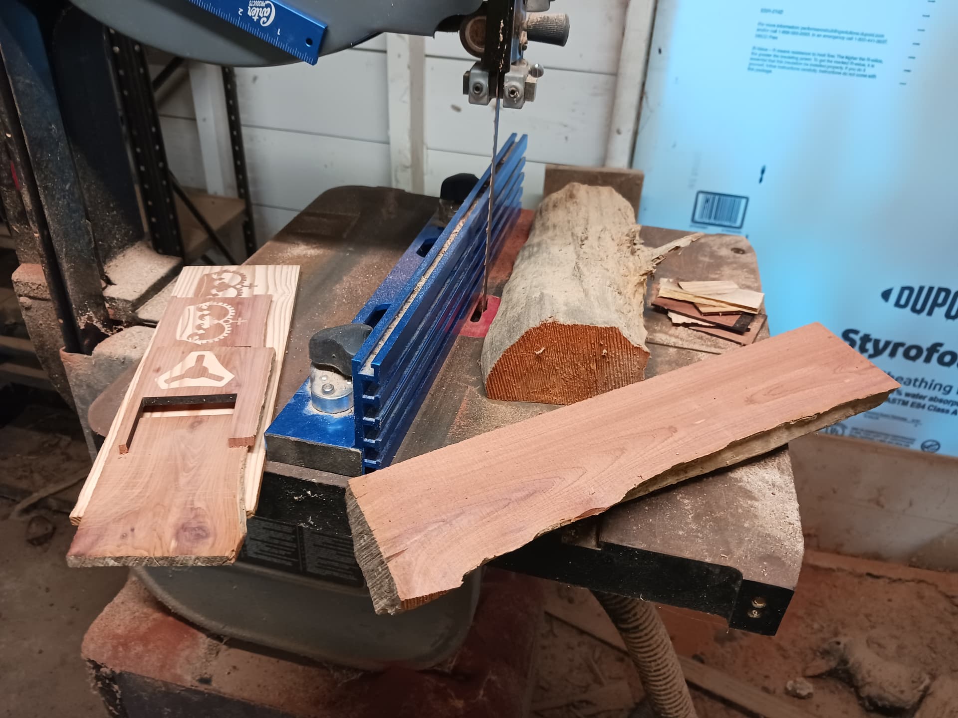
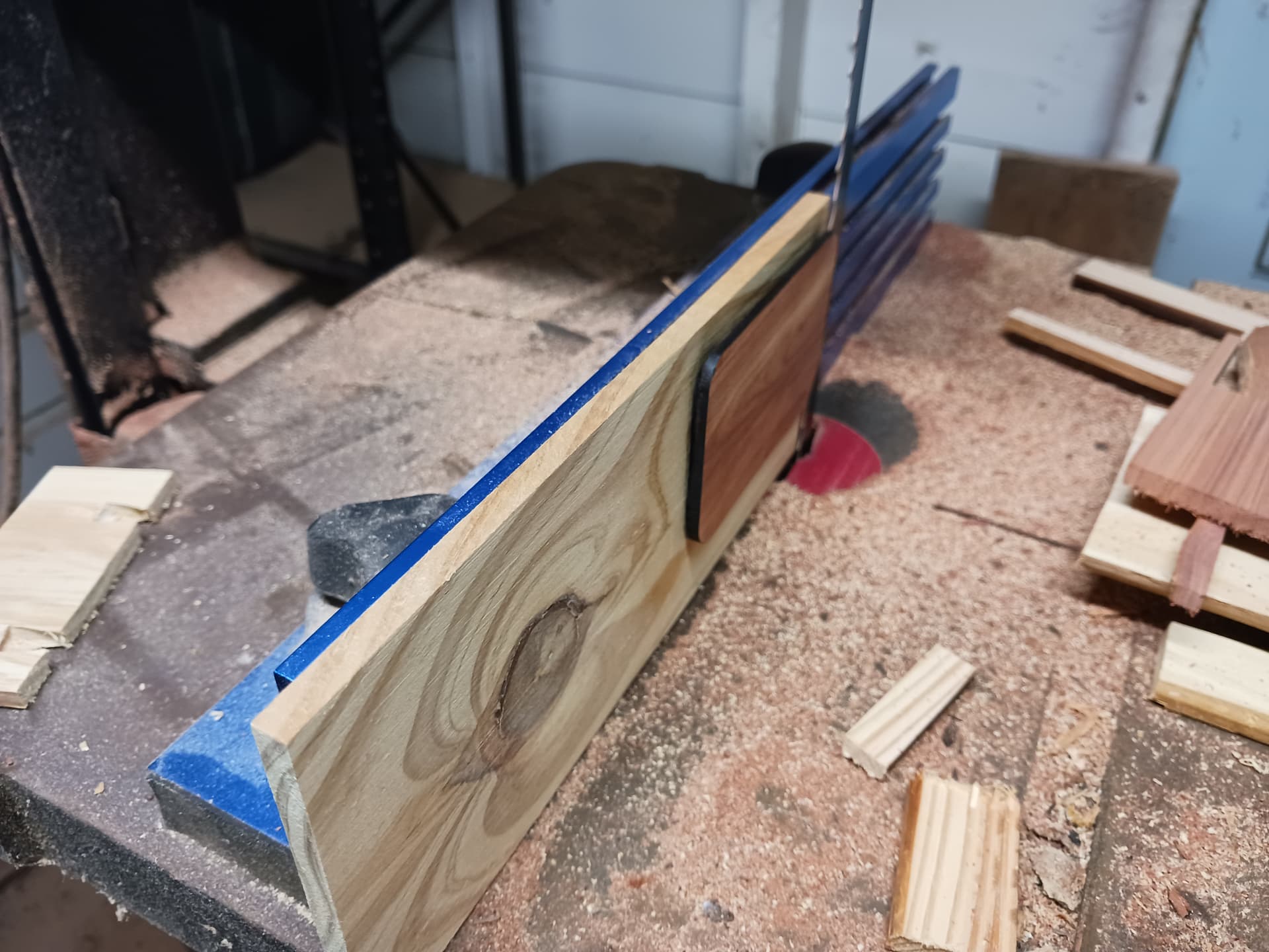
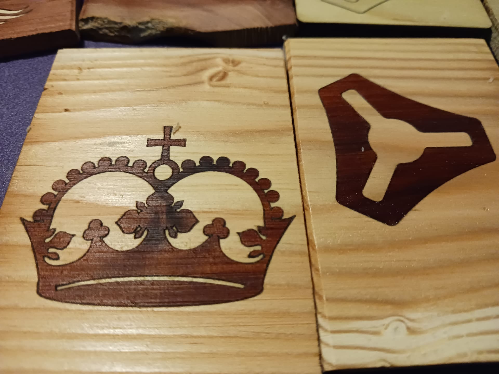
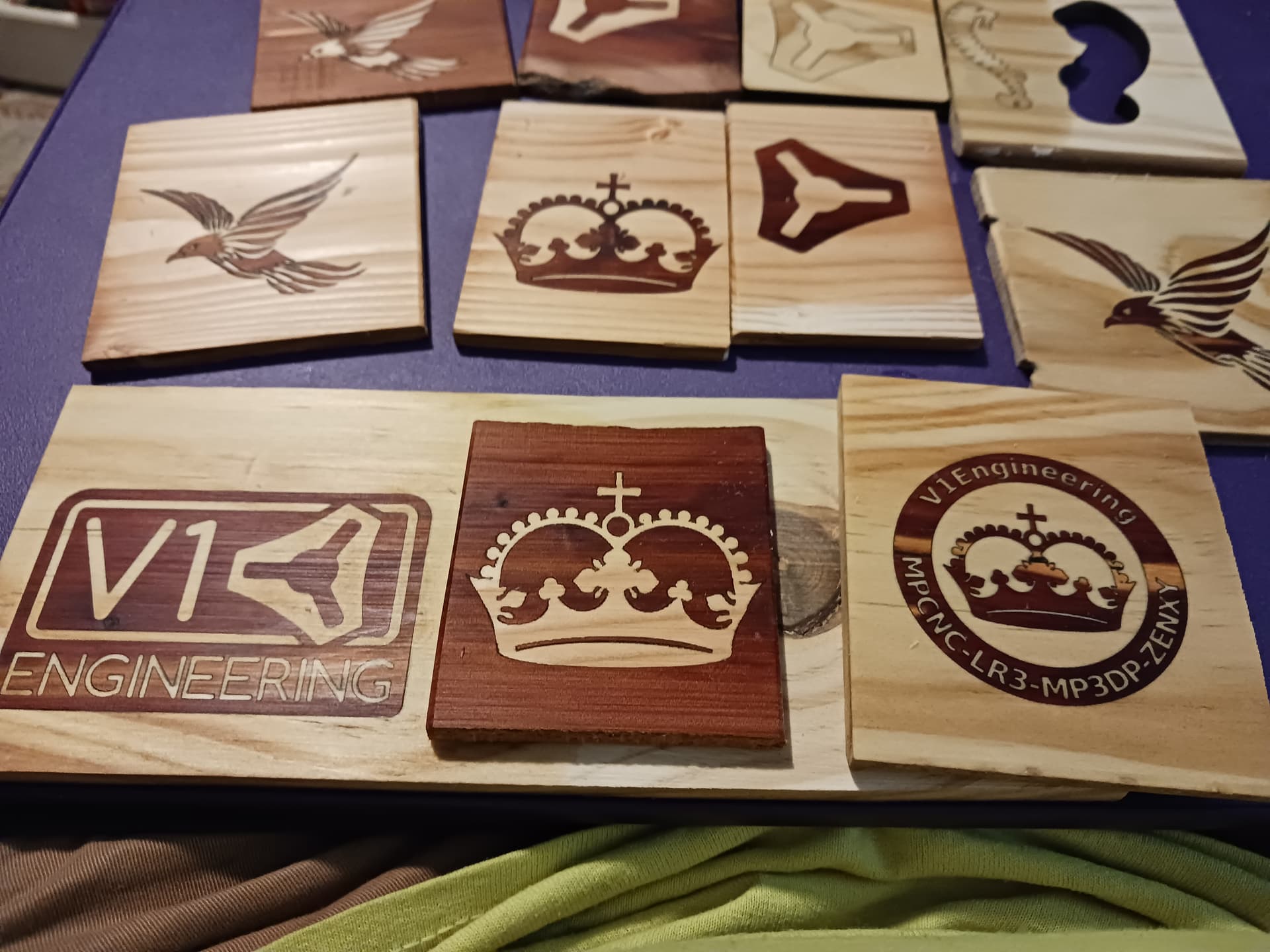
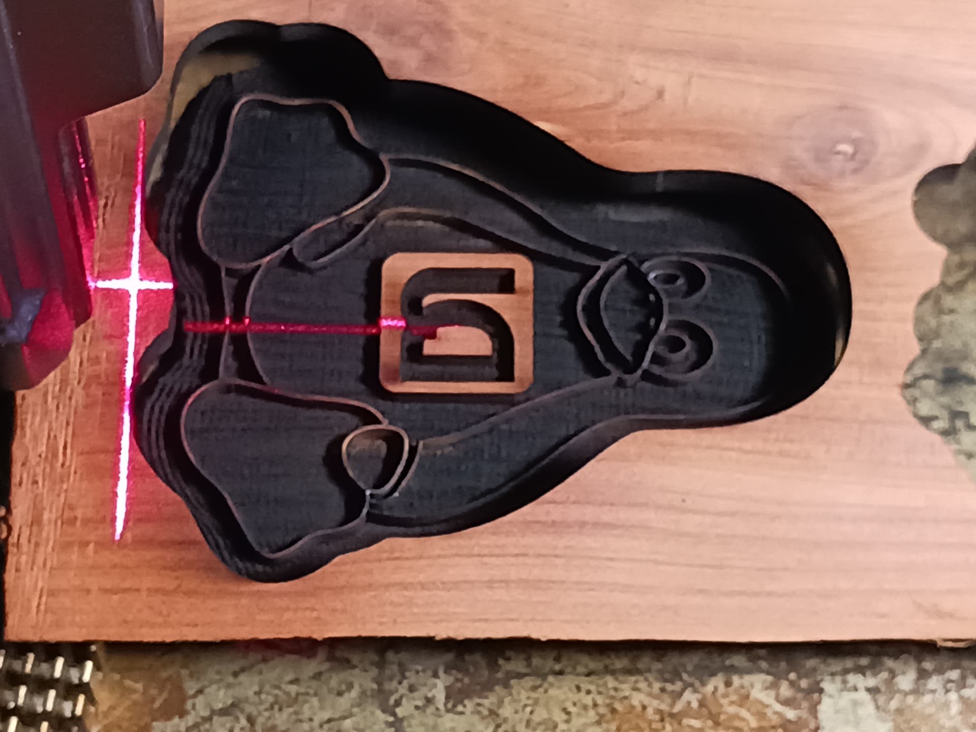
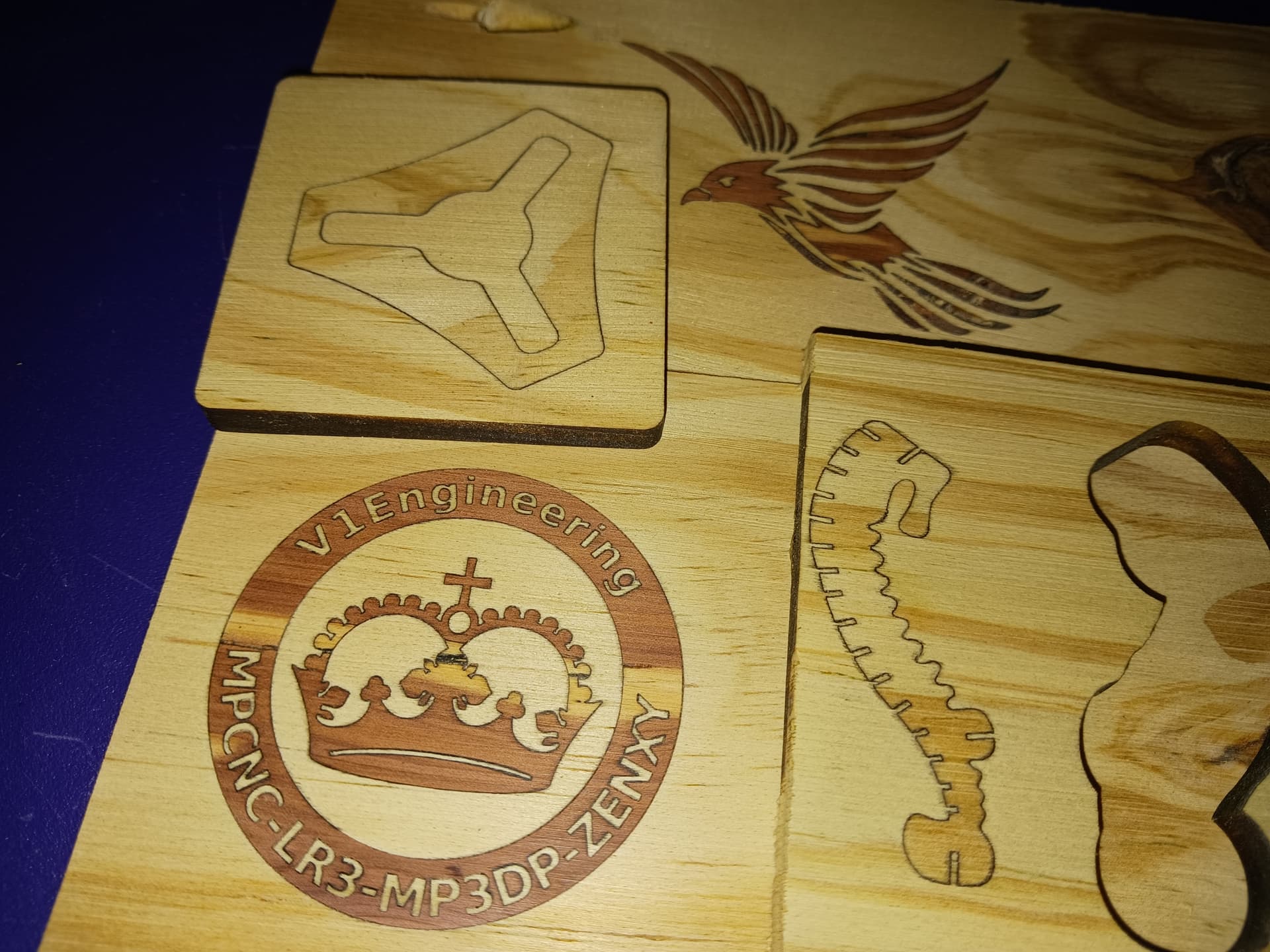
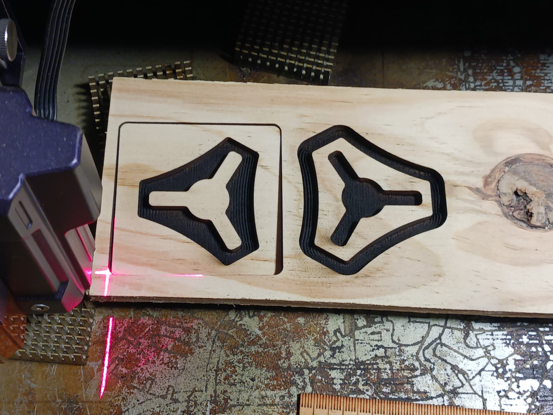
You can export the gcode to process just one, or both, of the “pocket” and “inlay” images. I show here both to the same plank of material…
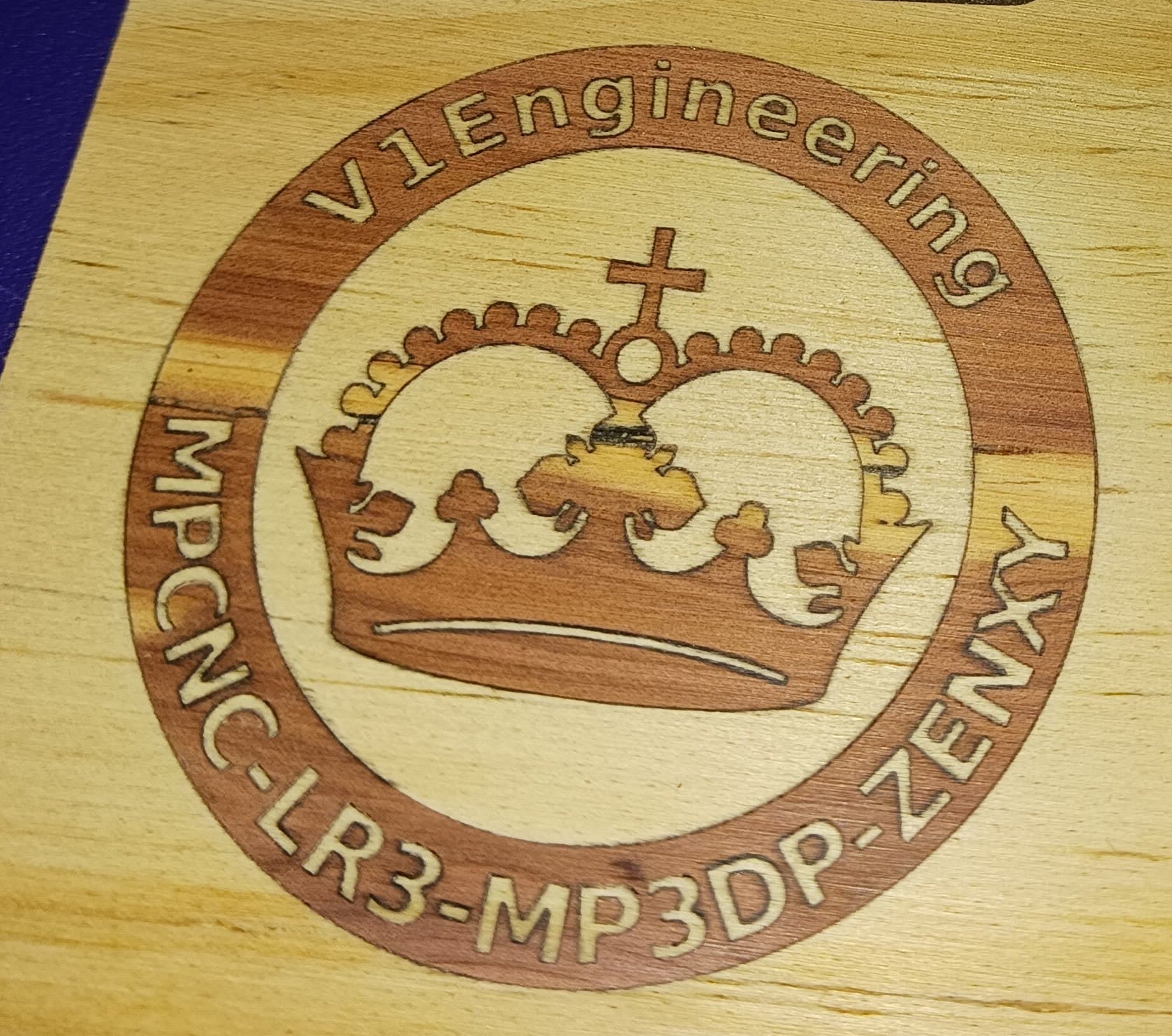
The topmost image is the one using the method just described…
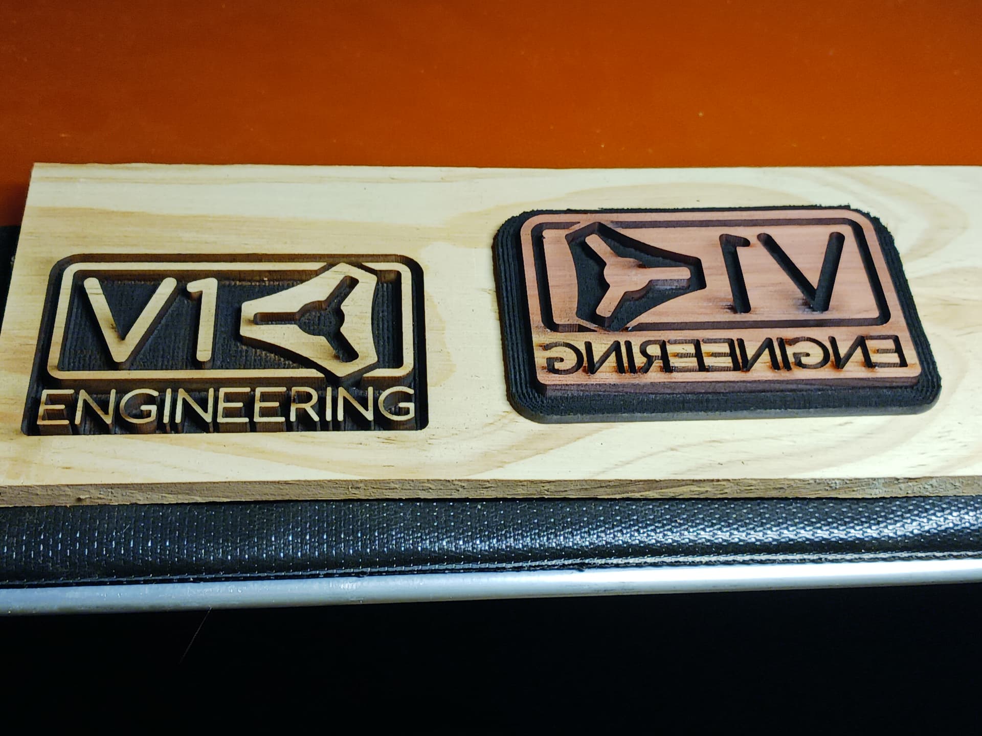
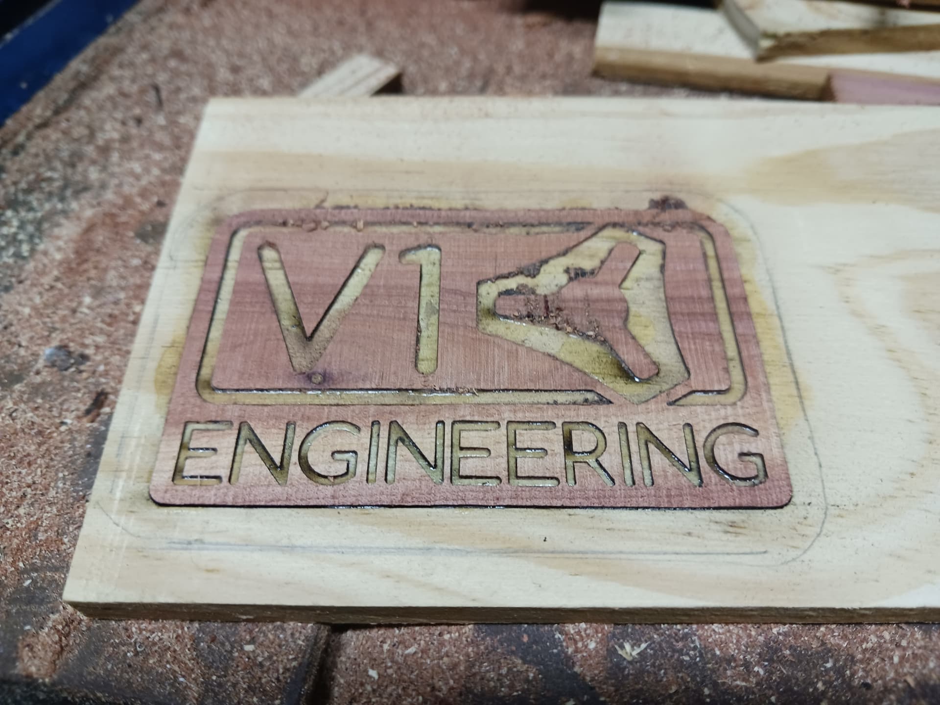
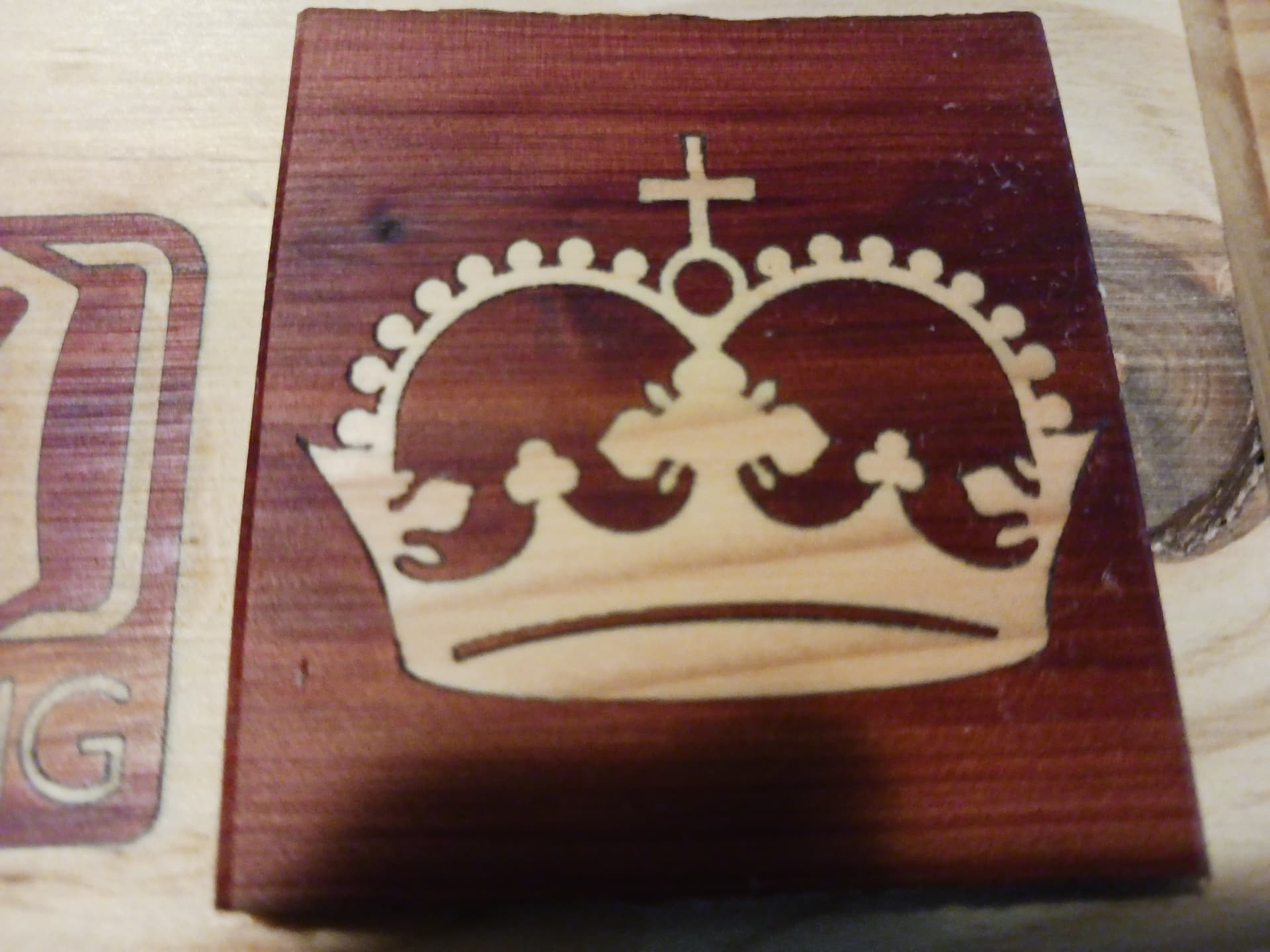
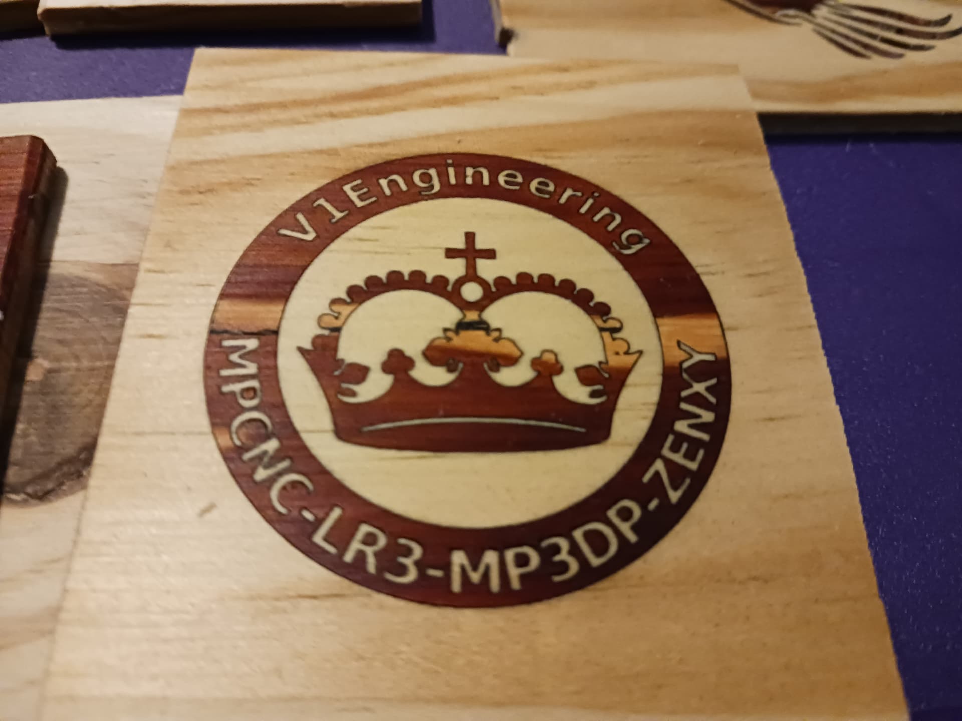
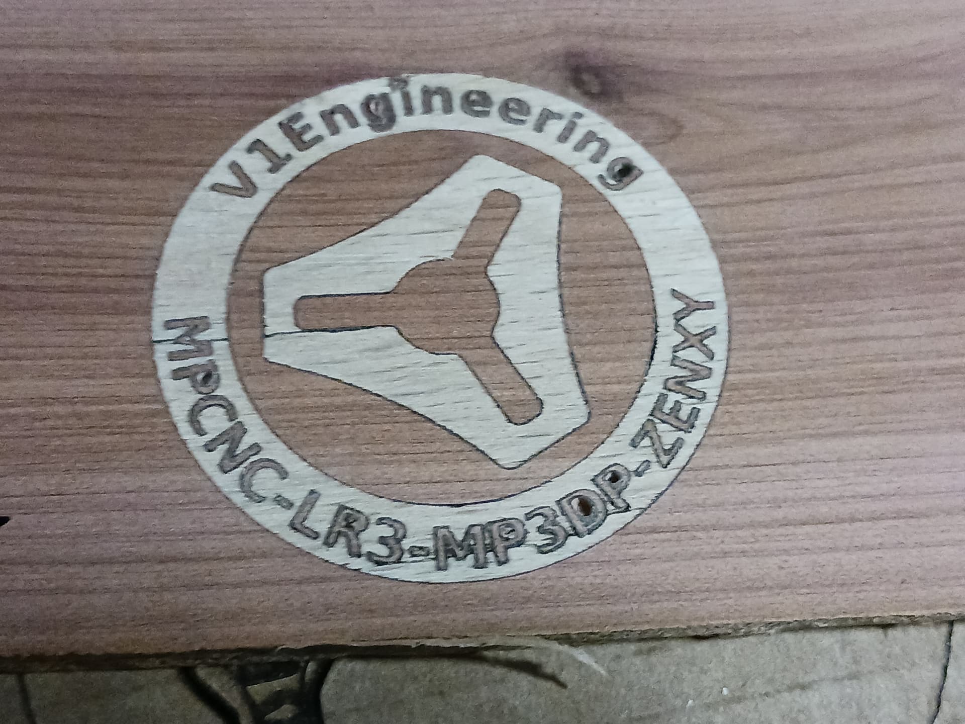
Here, the V1 logo is also done in one material for fit-check…
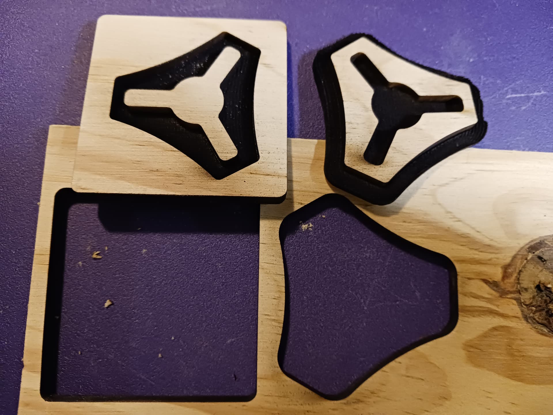
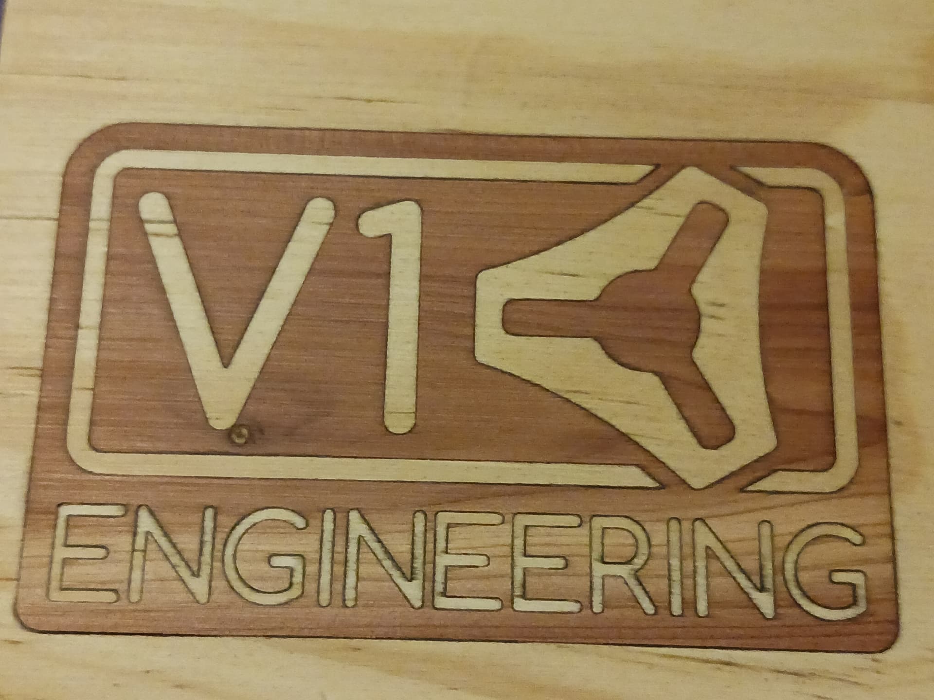
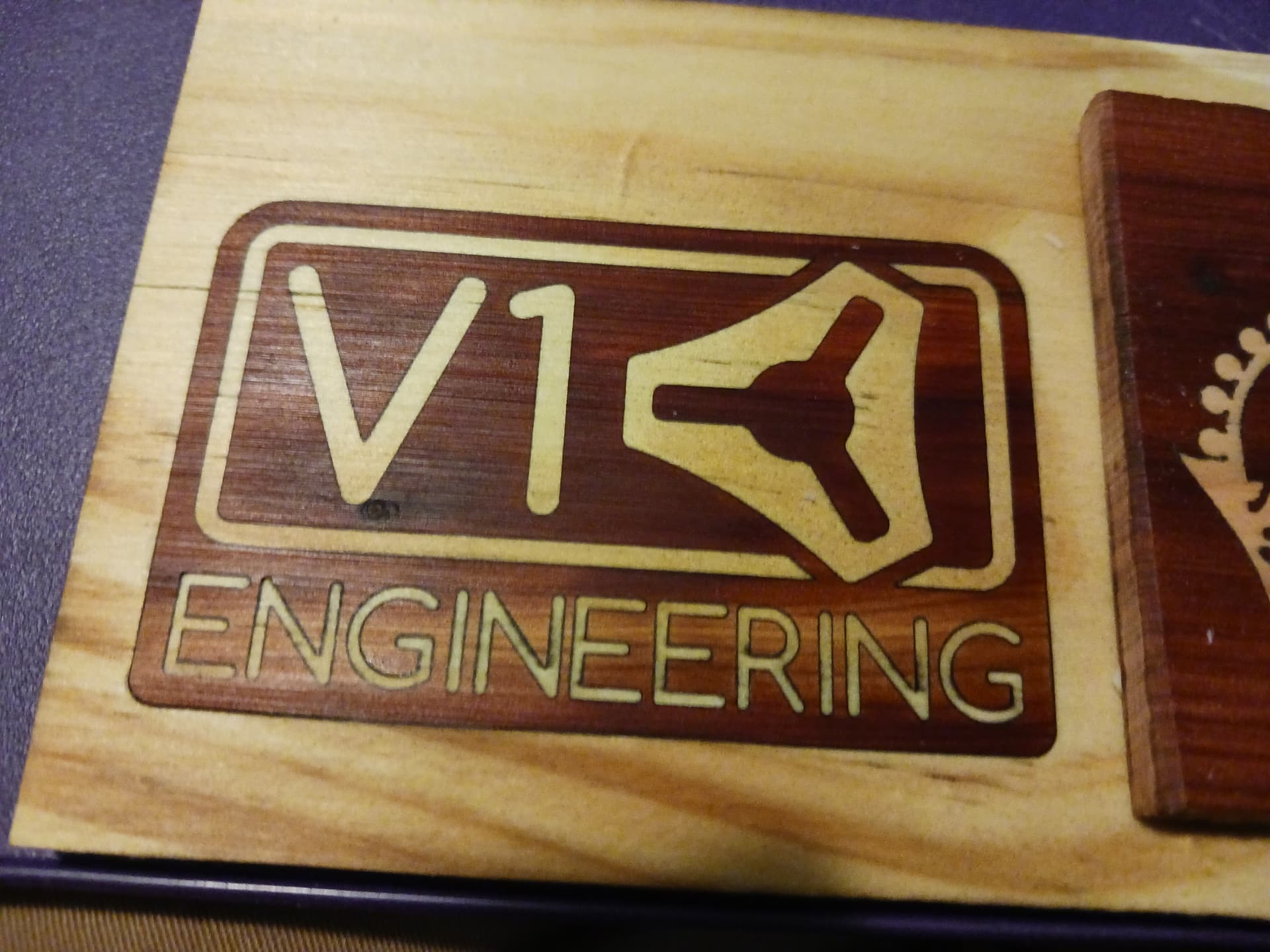
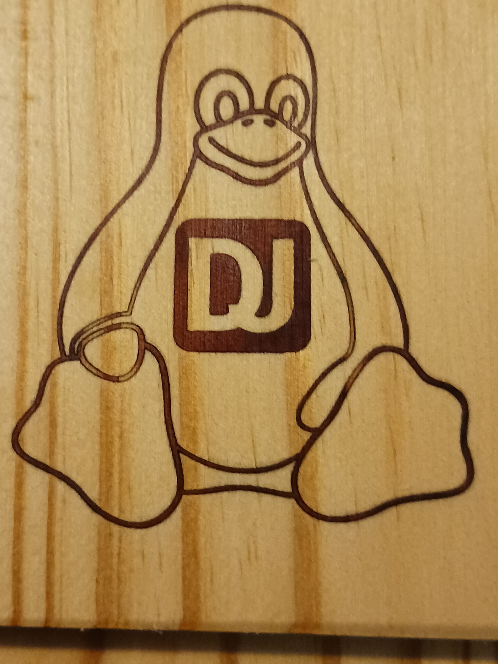
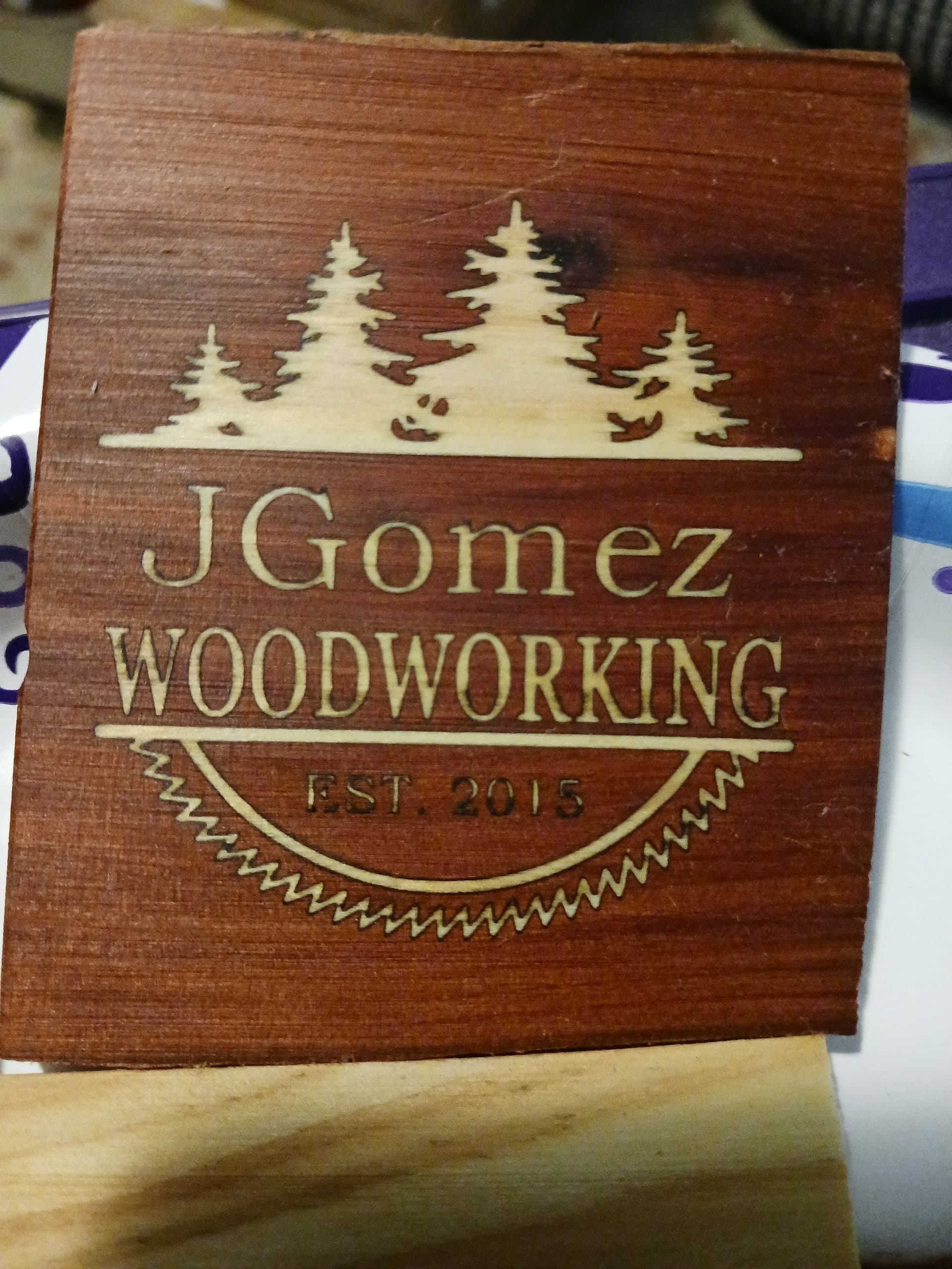
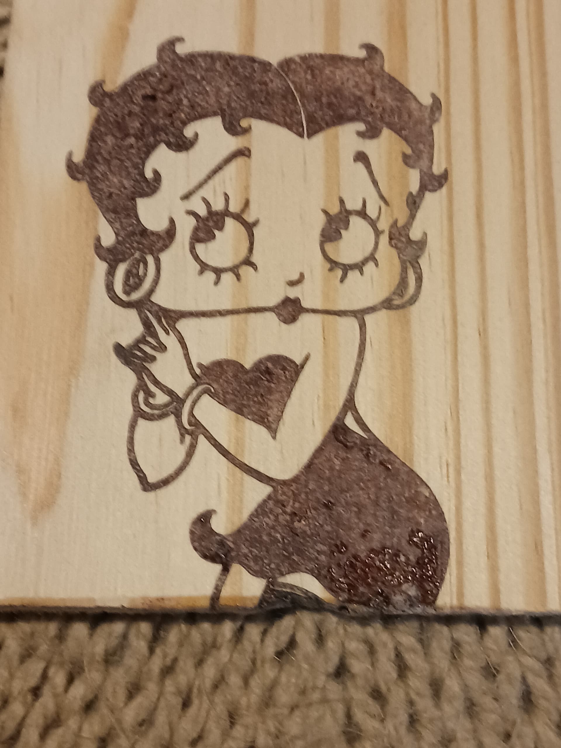
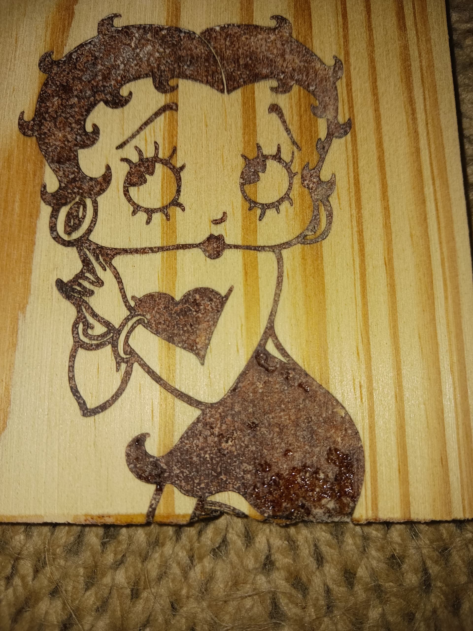
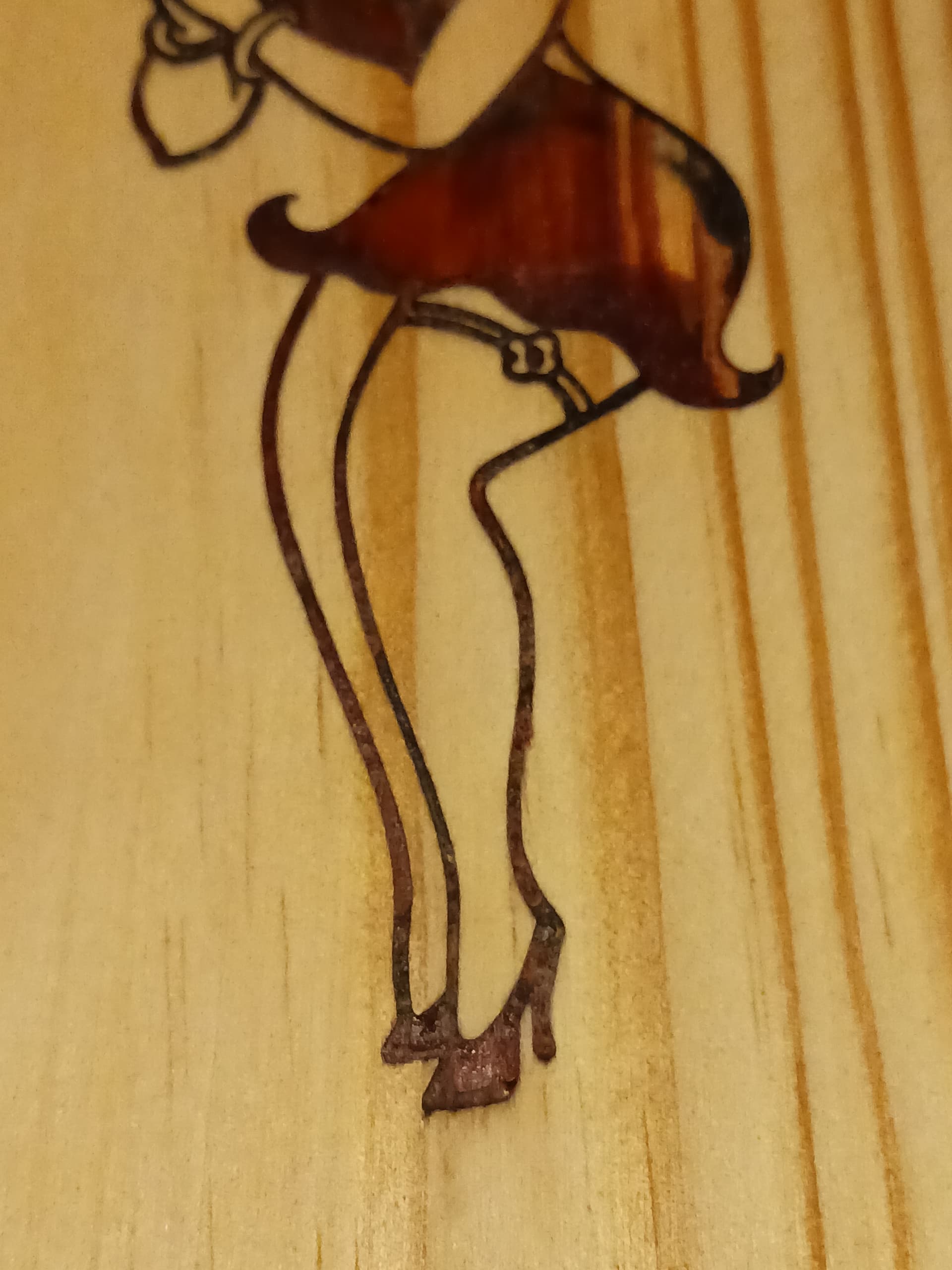
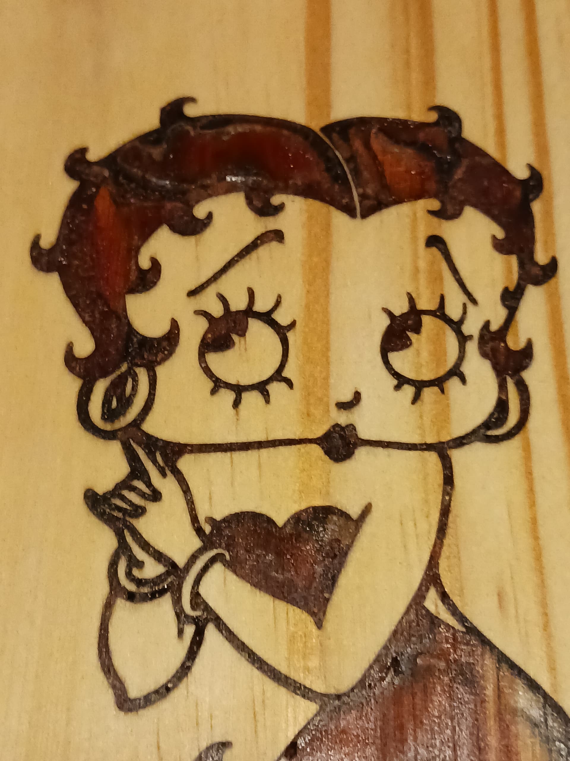
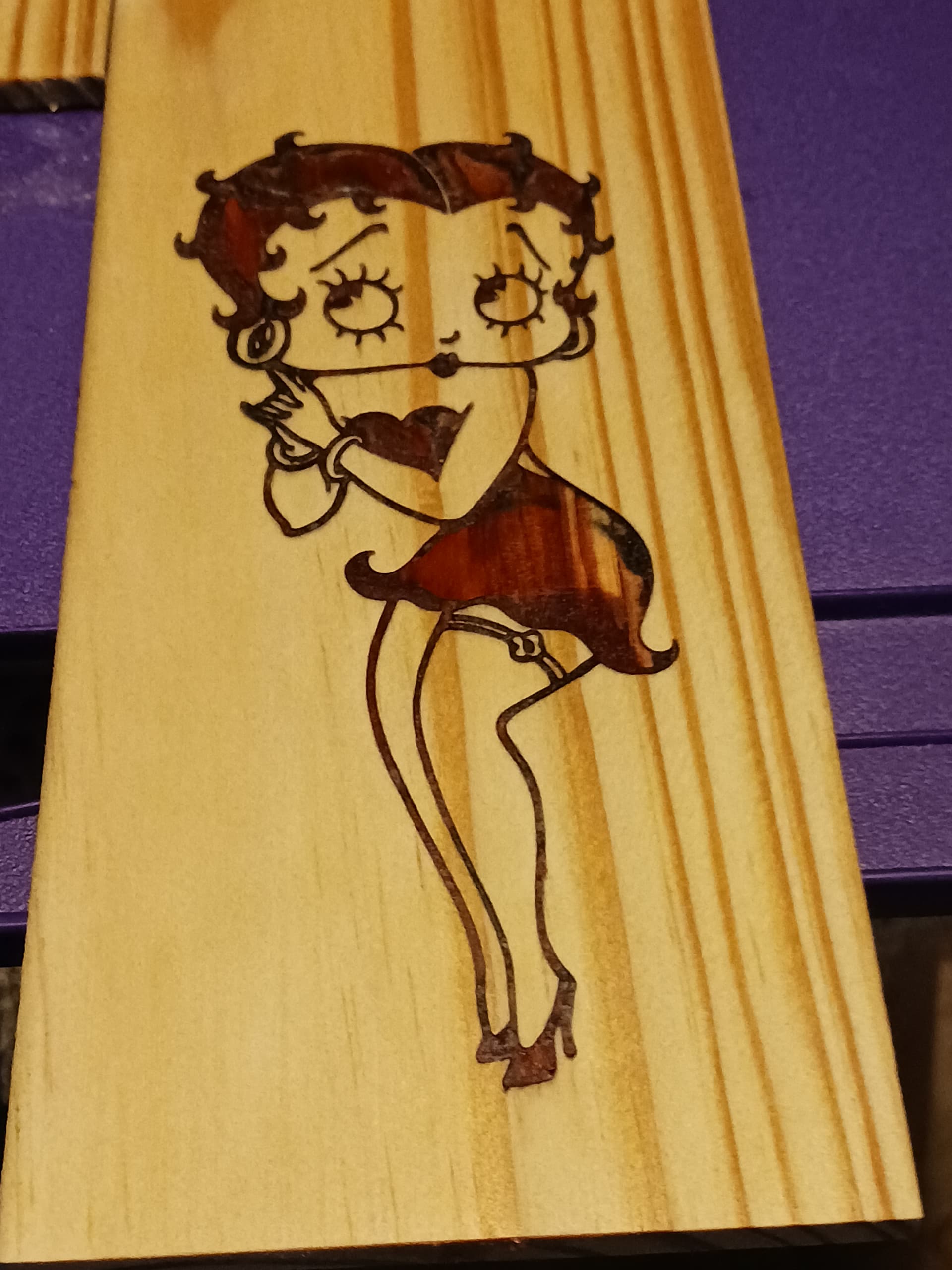
Finally, the “pocket” and “inlay” gcode files are run separately, on contrasting materials, to achieve the most striking results…
Ratty materials will, of course, cause the usually voids and imperfections that will need repair with a little glue and sawdust… but the kerf lines should look uniform and clean, regardless.
I also found that CA glue can be used (if it has sufficient working time) rather than the white wood glue… and it greatly speeds up the process. No more overnight waiting… you can have the finished inlay merely minutes after glue-up.
– David