For the benefit of anyone coming late to this party - here’s how the book says to square the mini!
2 Likes
Whoa that is crazy! At least they do mention it. I was looking around for some faster calibration prints the ones I made to take a long time, I will have to do some tests to see if I can make it faster somehow.
I really really like having a dialed in printer, it is worth the effort. Things fit better, but I guess that is because I tend to like projects that have multiple or moving parts…
3 Likes
I know, thanks. But if you read through it, you will see that XY squaring is not in there… ![]()
The MK3 has a software option to measure and offset it, the Mini does not.
For me it’s just another machine, so I take the same time that I would on a Saw or planer (OK it’s only a zillionth of the time it takes to properly dial in a jointer) - a digital angle gauge can be incredibly useful to check things quickly before and after the whole squaring procedure.
1 Like
If Y, XZ and YZ are square - does it not follow that XY will always be square? I would have thought that the out of square base to your print is due to a warp in the XZ?
But I am confused by all these X’s
1 Like
No, XZ is fine, as is YZ, those can be checked and adjusted reliably. XY would be twisting the arm back/forth, which they do not have in there. I guess there shouldn’t be any twist. ![]()
1 Like
Not trying to argue, just get this right in my head - if that was the case, and everything else was properly squared, wouldn’t you still end up with a perfectly square model but not parallel to the sides of the build plate? Which is why there’s no need to square it?
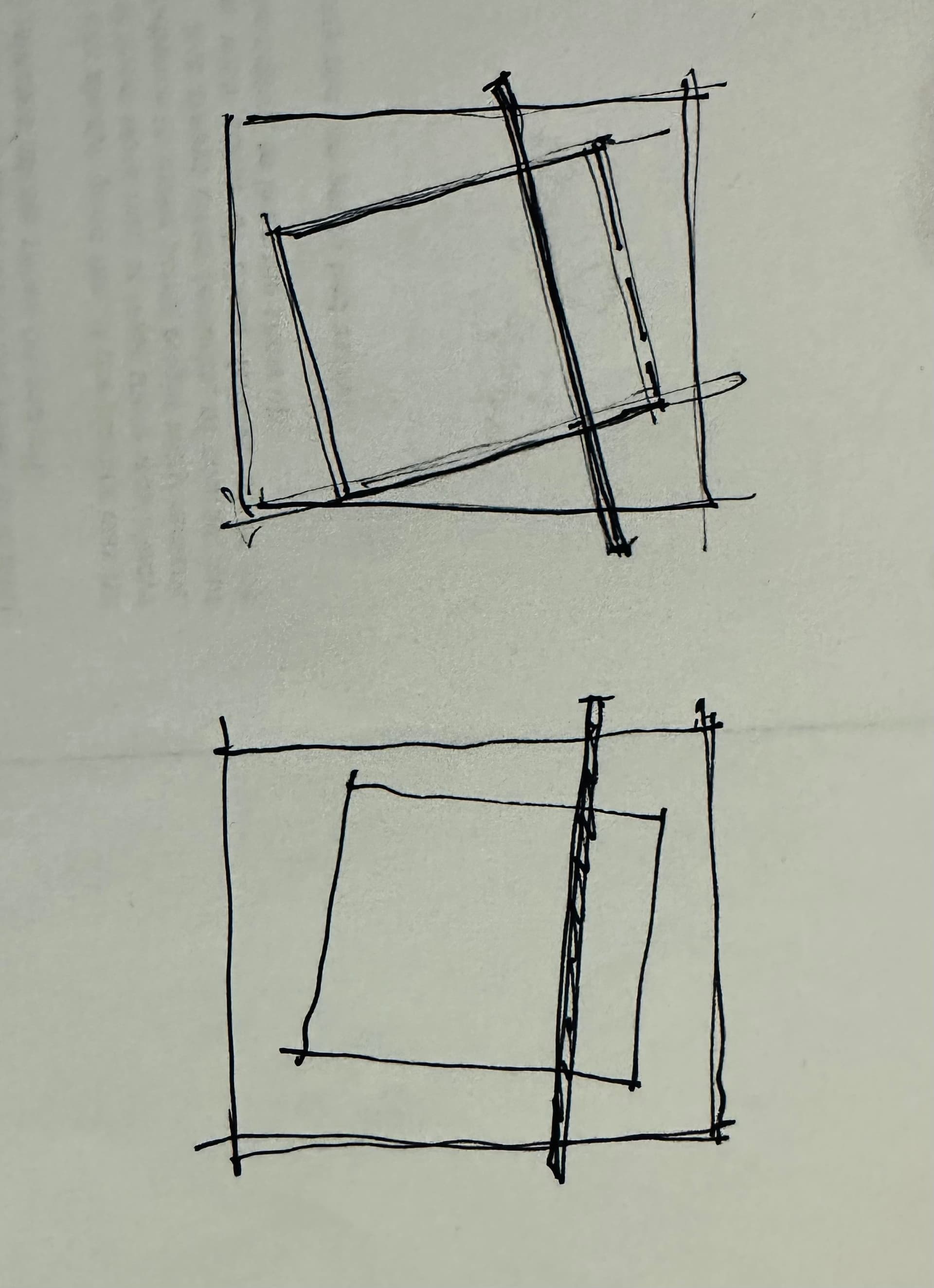
I can’t really explain the maths to you, but there is a difference, maybe because there is only the one arm? After I was physical, it now is square. I tried to draw it as well, but it does not make complete sense in my head. ![]()
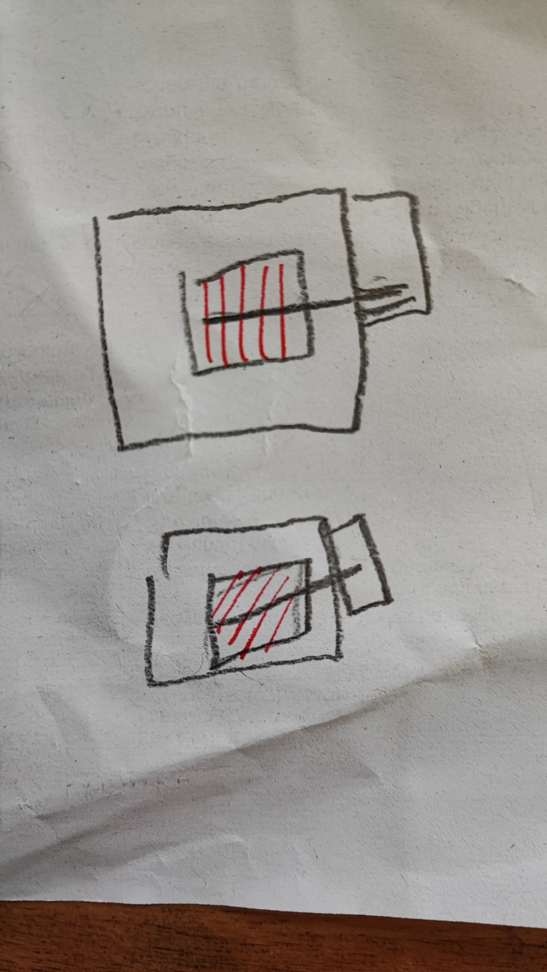
/edit: @bitingmidge I figured it out, with a printer of Ryan’s design, X/Y are one axis that moves in one direction, so what you drew would happen. For the Mini as a bedslinger X does not know what Y is doing, so the bed, Y, is going straight, while the X is crooked. That’s why the twist happens.
3 Likes
@vicious1 I think I have figured out why the LR made groves when planing on the left side when everything else was straight. It could have to do with the brackets as well, since the ends are printed A/B, hence the orientation on one of them is different. So the 1mm error in my printer gets multiplied by 2 because of the mirrored part.
I really hope this is the reason or all of this. ![]()
That would do it. I have thinking about ways to change this, or some test parts for people to print.
1 Like
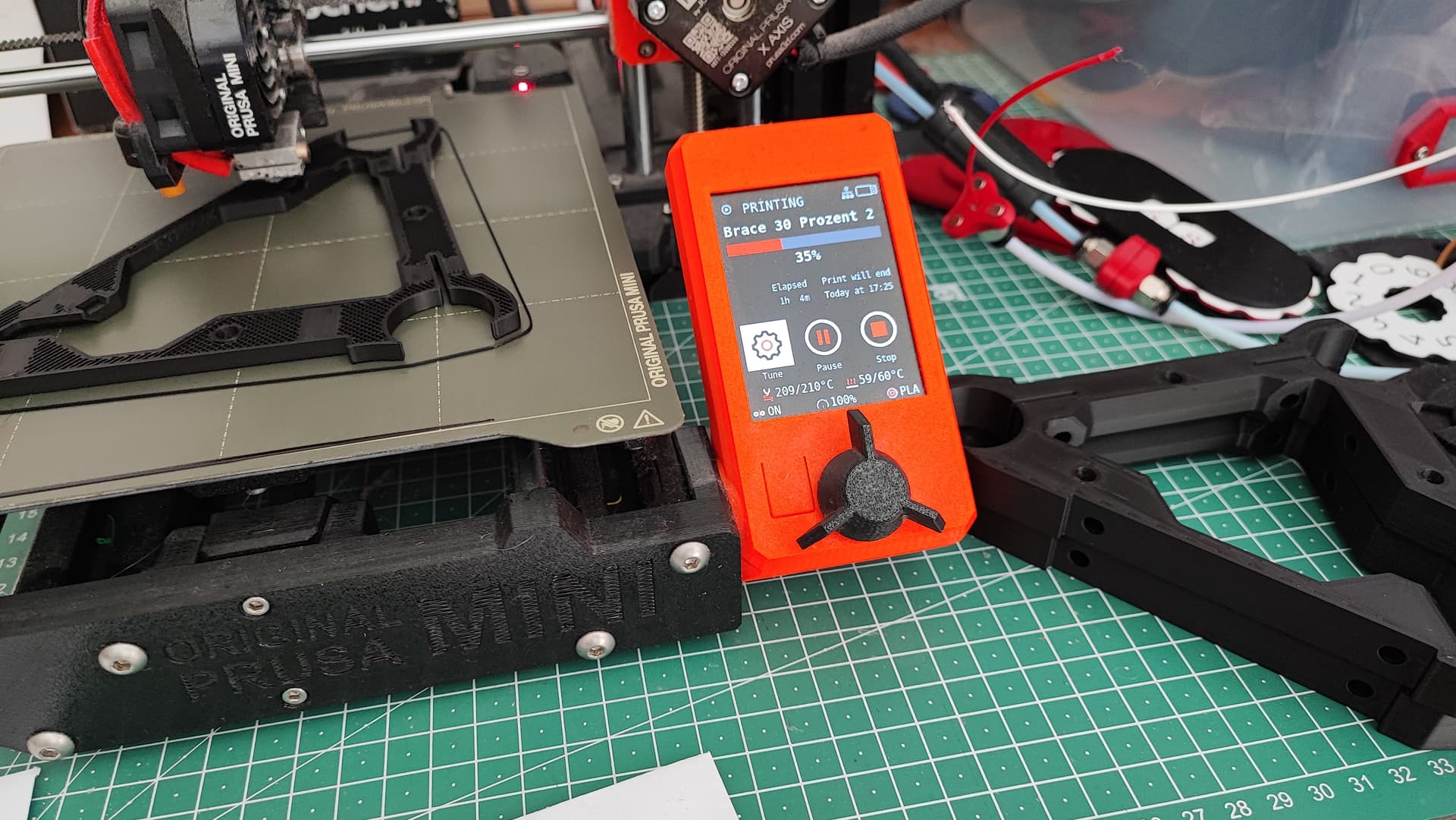
Okay, it was not the braces (at least regarding the rubbing, it might have eliminated the other mistake, because they do look a tad different when placing them next to each other, like 0.4mm diffferent). It took me a while to undo all the wiring thanks to the TB6600, but I swapped all the braces, installed the bottom plate and just set the core on the rails. It looks basically exactly the same and it is still rubbing when I fasten the core’s screws to eliminate the rattling. Interestingly enough I can now see where it is rubbing: in the middle of the core. The cutout where the braces are going through is not even but coming up a little in the middle. I now have three options: sand it down at that part and hope the core is still stiff enough, try the core that warped while printing or print another core. I am kind of trending towards option one. ![]()
Thinking about it… it’s 8 screws, maybe should try the other one first… ![]()
Mayhem:
So you had the core so tight it pulled in the X rails and bent the braces?
Nah, the braces were definitely off because of my printer, that’s what I mean. ![]() And the core must have misprinted because of the same problem. Or because of the colour change. What do I know… -_-
And the core must have misprinted because of the same problem. Or because of the colour change. What do I know… -_-
That would have been a first and I would have renamed the whole thing to The Hulk… ![]()
1 Like
Did you roll the tubes on the floor to see if you had a banana ?
If the braces are loose does spinning the tubes by hand show a spot that has more drag spinning than others?
No, they are fine. It’s the same rubbing for all of the braces, so it’s not specifically about a bend tube. I am going to try the second core, then sanding, then reprinting. ![]()
1 Like
What a mess. I feel sorry for you. I‘d probably go with your option #3 an reprint the core…
Well I hope to be building a beam today, I will be taking a long hard look at it. your printer was pretty far off, but maybe I can figure out how to get a bit more adjustment for an LR4.
Thanks. If you made the bottom have a mm more room (Der Froschkönig - Lowrider 3 in Oldenburg, Germany - #181 by Tokoloshe, picture 3), then I think it wouldn’t be a problem at all. I know this is not your mistake, but maybe you could plan these parts with a little more tolerance? Or is the mm important for stability?
1 Like