@SupraGuy: Thanks for the calcs. For a prospective main design, I’m going to be sharpening the pencil so to speak, to target using only one 4x8 sheet of plywood while getting the best rigidity and greatest reasonable quantity of ribs and spars out of it. I am not aiming for usable storage space inside the torsion box in that instance.
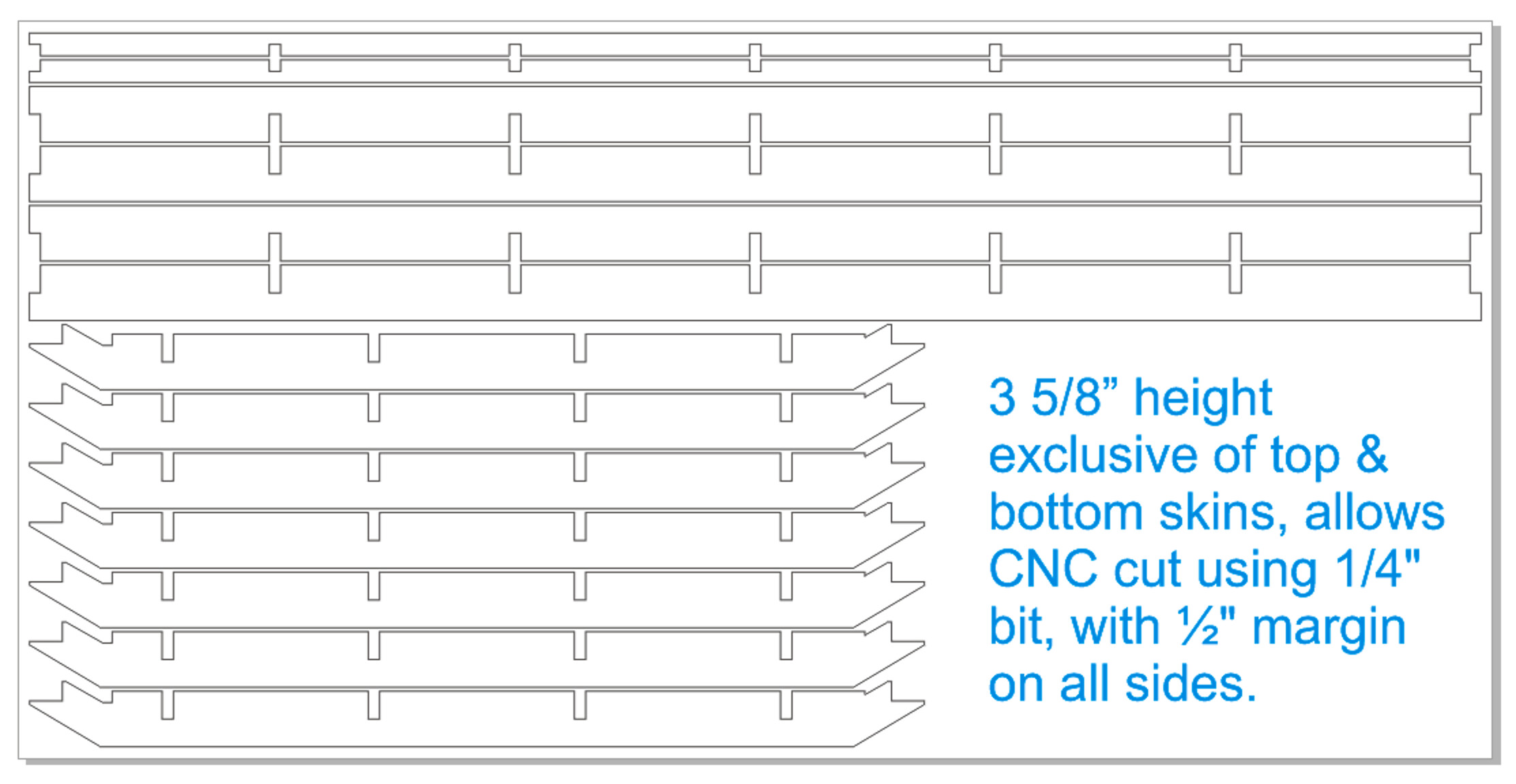
The screen shot below is based on 2D vector manipulation of the design, but I am fairly confident that reworking the 3D model will support this. This potential cut plan shows using only one 4x8 sheet and yet getting four (4) main Y spars and seven (7) main X ribs, plus two minor Y spars on the extensions for a place to attach metal struts. The lower right corner of the sheet has some free room for cutting additional pieces that could be “laminated” or “scabbed” onto the minor Y spars for a version of this that has wooden side rails for the LR3 to ride on. These drawings are based on a 3 5/8” height for the torsion box body, exclusive of top & bottom skins, and it would allow a CNC cut using a 1/4" bit, with ½" margin on all sides.
Awesome. Im planning 2 builds. A 4x8 stock one and a 1700mm x 3000mm build (but first i need to sort out the space issue on my shop, maybe move or get the shop bigger i still have space to grow)
Hi Doug - very good work on the parametrics. But the holes in the spars and ribs defeat two of the aims of the part. 1) Holes cost money and unless you cut a hole then use it as a part then this is a conflict and you pay more for the function of the part then needed to 2) The hole means the local bending stiffness is reduced hugely and the local shear path has been removed. A “torsion box” depends on local shear stiffness and the holes have removed all of the local stiffness. If the holes are to reduce weight, then they need to be triangular like a truss. This improves the local stiffness over a large hole and reduces weight. Peter
@peteeng
Thanks. There are no holes in either the ribs or spars in the version I’m working on now. There were holes in earlier versions (above) based loosely on a Ron Paulk-inspired approach, but the shallower version I’m working on does not have room for the holes or any need of them. You can see a rough 2-D sketch of the current work in this post here:
I’m actively working on this even now, so a delay is advisable.
The reworking for shallower cut plan so that a torsion box can be cut from a single sheet of plywood has not yet been done on the version for metal struts.
The shallower plan for the version with wooden side rails is closer to completion, but the F360 archive currently available for download is not the latest — pending update happening soon.
There are two links for each — because I am not on the paid version of F360, I can only offer a live preview via their cloud, and I then can offer download of a Zip file containing a Fusion360 archive file that I manually upload to my own website. Which link are you clicking? Which table version, and of that one, which of the two links for it?
I’m prepping DXF files for a variety of cut plans
I’m prepping to do test cuts to check tolerances on real life assembly based on actual measurements of thickness of real plywood.
Bottom line, waiting is advisable, but I’m still unable to advise more unless I know which link you’re clicking, and what you see versus what you expect to see.
I was trying to download the .zip files for both designs. Finally got it to work by copying the link URL and pasting it to a new window, not sure what the problem was.
OK, I was able to reproduce that, and I think it was a “browser security” issue. I edited the links to change http:// to https:// and now the download happens on the first click, no pasting needed.
Until now I don’t think I have ever bothered with closely calibrating my LowRider for dimensional accuracy. Things I’ve been making don’t depend on extremely close dimensional accuracy. However, in order to get the cross lap joints (aka half lap, as cross lap is seen as a type of half lap) to work well and tight, the cuts need to match the real world thickness of the plywood. So, this calls for not only carefully measuring your plywood (believe it or not it comes in a variety of different thicknesses, 21/32, 23/32, actual .75" etc) but also checking that if you wanted to cut X you actually are getting X.
The bigger of a calibration check you can run the more accurate the results.
I know I need to adjust to get better accuracy because I just ran a small test (20" in X axis and 30" in Y axis) and I was off by about 2/64th across 20" in X and by about 3/64th across 30" in Y. That’s about 1/64" per 10" of travel.
I enter my original steps (100 per mm), the distance requested (29" = 736.6 mm), and the actual amount achieved (in my case ~735.40938 mm), and the calculator tells me I need to increase the steps from 100 to 100.16.
The calculator page also has the needed commands handy right near the result:
Enter the following in the terminal:
M92 X100.16
Followed by M500 to save to EEPROM.
M500
So, I’m off to make those changes to X and Y, and then check again.
Excellent results on my first test for CNC cut cross lap joint! Video below.
I’m using my LowRider v3 CNC to cut “test” spars and ribs for prep for the torsion box, my result was fantastic. The LR3 CNC is calibrated for dimensional accuracy. My test cut was based on the exact thickness of the plywood (as measured with calipers) as the width of the notch, and exactly half of the height that was to be cut as the depth of the notch. IMPORTANT: I did remember to enable the “Overcut” feature so the inside corners would not be a problem. By use of a hammer to drive the two resulting pieces together, this test was a huge success with a perfect result! Amazing friction lock on the two pieces.
For LowRider v3 CNC, full sheet capable table, Part 1, prep & cross lap test
If you use the 608 skate bearings as wheels, they will deform the aluminum, but I think it would be fine if you use the 60mm rollerblade wheels. The softer material will mean that the roller wheels will take the wear, and they’ll last several years.