I’m currently using the LR3 dimensions calculator in the V1E Docs to verify the dimensions of these table design efforts. I am running the numbers on 49" x 97" assuming the table will want to be used to do spoil board surfacing on a 49" x 97" MDF sheet.
Please note that to err on the side of caution, I am also allowing thickness for printed XZ plates, as well as some extra in accordance with this statement in the docs:
An extra 25-50mm (1”-2”) or more on each dimension is nice if you will be pushing it up against a wall or in a corner.
So, once I run the numbers, and come up with a table size of 61.75" (X axis) x 112" (Y axis), I am adding on 1.25" on X, for a total with of 63" and adding on 2" on Y, for a total length of 114."
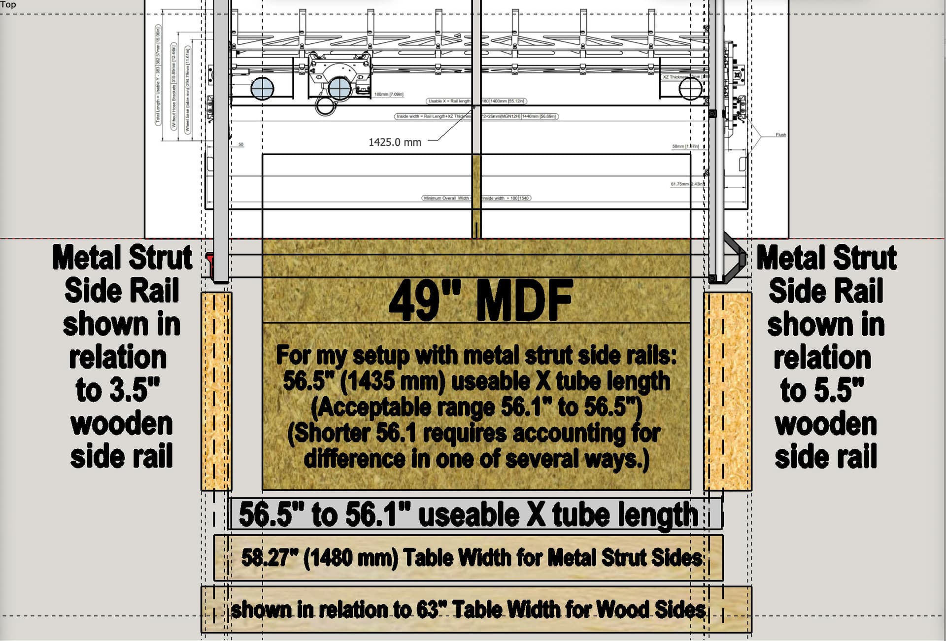
The above is for the version with the wooden side rails. For the version with the metal struts for the LR3 to ride on, the width comes down, and printed extenders for the Y belt tensioners make up the difference.
With the variance possible with the XZ plates, there needs to be some capacity for different belt mounting width on the wheel side. The rail side too, come down to it because it will have a different offset from the spoilboard/cutting area.
The XZ plates are different thickness. My Aluminum ones are 1/4" and the printed ones are wider. That changes the calcs. The calcs show where plate thickness matters.
Yes, my thinking was to have enough of a “riding plate” (for lack of a better term) on both the inside edge and the outside etc, to accommodate either thickness of XZ plate, with a little room to spare.
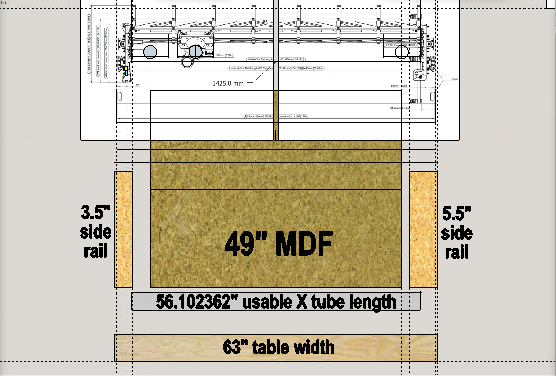
I’m using both the LR3 calculator and some visual reinforcement based on the illustration of LR3 dimensions, slightly modified for 49" cut width (for MDF that’s 49 x 97). Here’s what I am headed for, in general, as something that can accommodate both printed XZ plates and 1/4" metal XZ plates:
LR3 gantry placement, X-axis Tube length, etc. re. MDF for cuttable area
THE IMAGE BELOW IS FOR TABLES WITH WOOD SIDE RAILS (see below for image for metal strut side rails)
OK, got it. I’ve learned so much about Fusion 360 and use of its params, and so much about how to go at creating parameter driven things, as well as getting a better handle on the needed dimensions, that I may do it over, now that I can do it better.
After that, once you build one, there will be things that need changing. Then you might want to include some test parts for the offsets…Some people are going to want space for vertical mounting as well.
It’s funny how complicated a table can be, when a sheet of plywood on the floor does the job just fine. I have been thinking about ideal tables for eight years now. The part I have not tackled yet is adjustable height on a LR, I do on the MPCNC.
I have a vertical clamping surface on my table. I haven’t used it with the cnc yet (still). But I do use it as a work bench. It is very handy. Mine doesn’t do all those angles. Just 90*
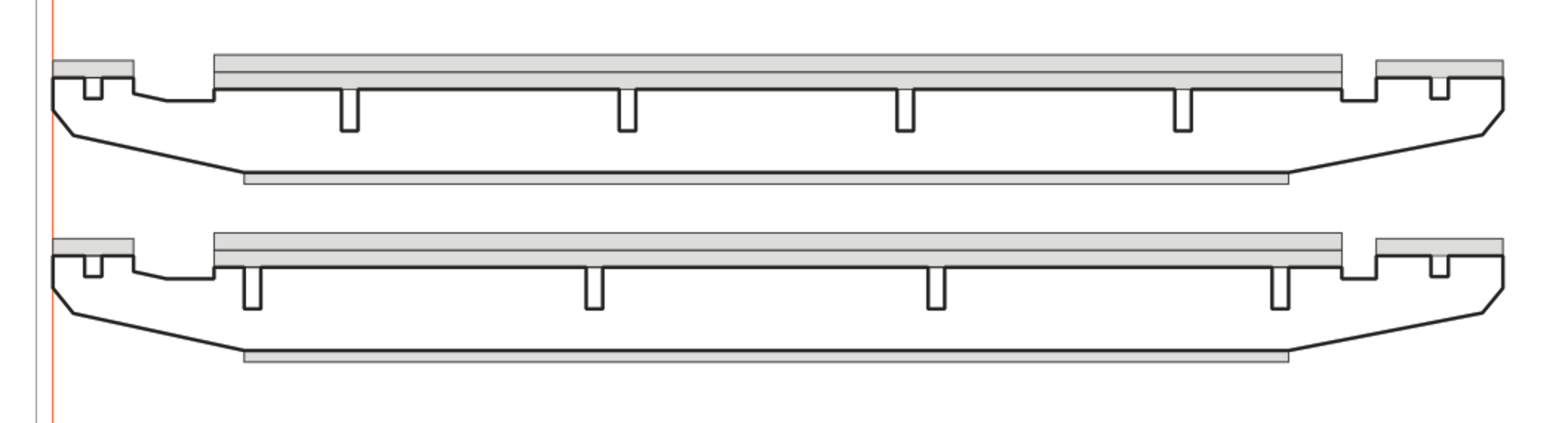
Has anyone found the gaps between the spoilboard and the Riding Plate™ useful? I understand having the two separate so the spoilboard can be swapped out, and there’s a limit to how close the bit can get to the edges to surface, but does the gap help with debris on the riding plate at all or provide other advantages?
I ask because I like the idea of a continuous surface but my LR2 design also has the gap and I’m wondering if I should keep it on the upgrade.
And this design clearly has the gap