Mind you, im using 10 bits for 12usd lol
3 Likes
Good Point!!
Same. We have been using basically the same bits for 10+ years, I don;t know that we have ever bothered to check.
When I build things my tolerances are ±1-2mm. From my previous jobs I know how much it costs to specify higher tolerances than that. So I would never notice something like this or the belts.
yeah, belts and endmills, tramming, leveling, surfacing…hopefully we only need to mention thermal expansion and humidity and not account for it.
Seems at year ten we have hit the point where sub 0.2mm is expected.
Jogging is okay, but that means tramming and Z level have an effect. It is best to use the router base and a very shallow slot along a straight edge.
As for measurement accuracy, that is never going to be easy. Several measurements averaged along a lot should be close enough.
1 Like
Oh, and I guess I should test all the bits I sell and add an updated diameter to the pages.
2 Likes
Smaller bits do really flex. Even 10.0mm bit will flex if you bush it too hard. That was the reason why I asked 3mm bits with 6mm shank in workblace. Also they were much more accurate in diameter.
1 Like
And so much more expensive… ![]()
2 Likes
This has been mentioned a few times, I’m not sure I’ve seen the results of that in this case.
3 Likes
Though - keep in mind not all routers being used have a base as an option. I’m using the carbine ER11 router on my LR4 and it does not include a base. I could put a bit into my dewalt with a base and do a test to measure the bit…but that would also introduce new errors by switching to a different collet/router. So an on-machine best approach to doing a test cut for measuring cutter width is good to specify as well.
2 Likes
Wow. I walk away for a few hours and the thread explodes!
I’ll try to take some measurements of the SPE endmills I’m using and report back. But I think I previously measured the 2-flute upcut mill I’ve used in most of my tests here and found it to be very accurate, at least as far as measuring the bit itself.
I’m currently using a Carbide 3D router that didn’t come with a base, but it might fit into the base for my Makita (provided I can even find it – it may have gotten tossed out in the last workshop purge…)
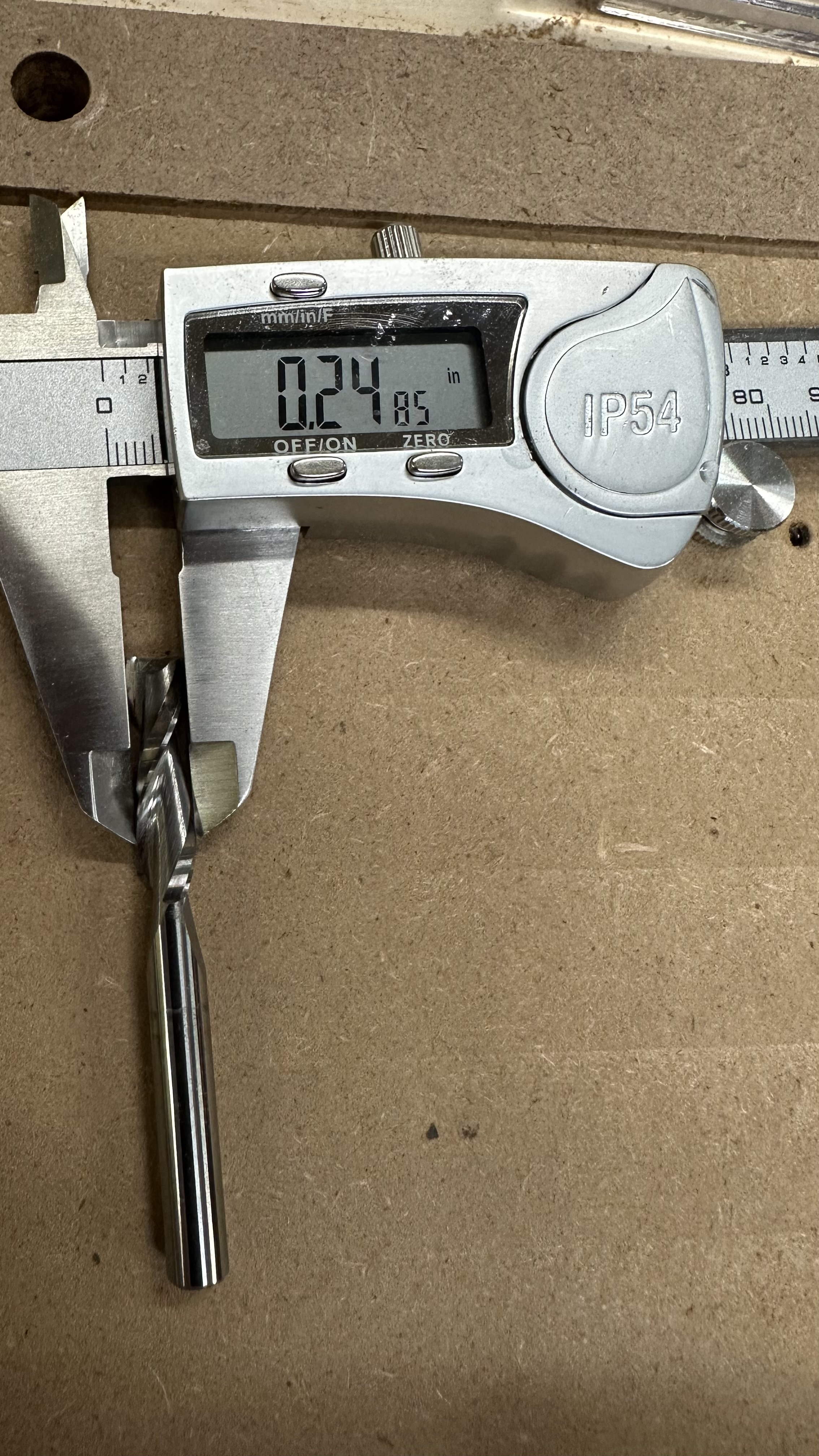
Ok. SPE Tools W04005 1/4” 2-flute up cut bit.
Measuring is hard. Taking pictures of your measurements is even harder.
Bit:
Cut results: about 2mm deep in red oak, using the straight edge guide (carbide 3d router in a Makita base), speed at about 2 on the dial.
Climb cut:
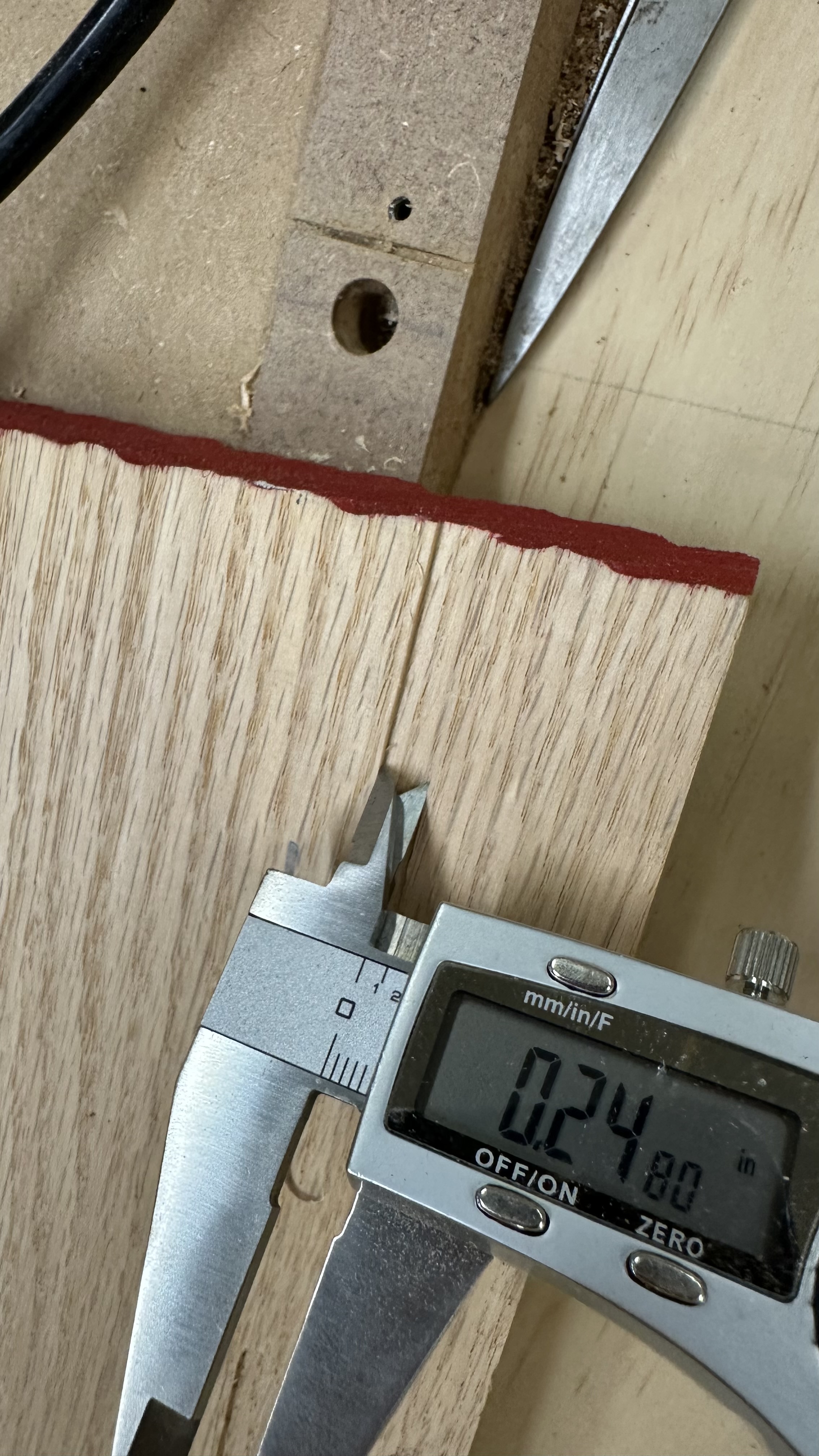
Conventional cut:

So the bit may be off by a few thousandths, but not enough to explain the results I’m getting.
1 Like
You lost me, could you please explain the difference between a climb cut and a conventional cut in a single pass slot?
1 Like
I assume he means cutting with the spin of the end mill or against the spin
I wonder what would happen if you cut the slot in your MDF instead of oak. Maybe the MDF is cutting differently
Maybe it has to do with which side of the router was against a fence? It should be conventional for this test. The bit should pull into the fence so there is less wobble.
I’m at a bit of a loss otherwise.
More or less. One cut was left to right and the other was right to left. Fence in the same side both times. No idea why the resulting slot is different width.
But the bottom line is that the endmill diameter isn’t the smoking gun we were looking for.
Lets not forget that slot width, ignoring rigidity issues (and further ignoring material type cutting variability in the range of low single digit thousandths), can be up-to the cutting tool diameter PLUS two times the runout… which may explain your larger measurement.
Measuring with guage blocks would be more accurate.
Cutting metals would be more accurate, too, if we’re chasing zeroes.
If the goal is just to get the part dimensions you want, then I think your test block is the way to go to find the effective cutting diameter. Slot size doesn’t matter. If you want accurate slots with an endmill you can’t be cutting them full width in a single pass… so should use a smaller diameter endmill if needed. Your test block method automagically accounts for tool diameter, run out and other sorts of positioning error. Just don’t get in the habit of changing the number of finishing passes or drastically changing feeds and speeds.
I remember a while ago I was claiming the v1 bit was 3mm not 3.175mm but I couldn’t prove it and I think I had other problems with my machine at the time.
I think that’s where I’ve landed on this – I’ll just fiddle with the diameter I tell the CAM program to make this test block come out right. For a given endmill, DOC, feed rate and finishing pass depth, I would expect that adjustment to be pretty constant, as it’s the value that compensates for flex in the machine for that particular configuration.
Fortunately, there are very few times when I need this level of accuracy – it just happened that the first “big” project I wanted to do was one that did. I think there were plenty of lessons learned in this process and I appreciate everyone who contributed.
Though I’d still like to see someone with a well-tuned LR4 produce an accurate cut of my test block without adjusting the endmill diameter in CAM!
1 Like
That sounds like a job for a German. @Tokoloshe
5 Likes
My family will be gone over the weekend, I am trying to fit that into the timetable. ![]()
Eeh, it opens in mm… So it’s 3mm not inches.
1 Like
I knew that was going to come up! ![]() I can whip up a metric version of the test block if needed.
I can whip up a metric version of the test block if needed.