So in another very long thread, I’ve been struggling with getting accurate cuts on my LR4. I’ve been through about a zillion gyrations and don’t feel like I’m any closer to a solution. (I’ll update that thread shortly with a summary of all the things I’ve tried - it’s a lot…)
So I put together this simple test and would appreciate it if a few of you could cut it out with your LR4 and share the result – either my particular machine is an outlier, or there’s some bigger issue with these specific cuts on the LR4.
Here’s the file as an SVG and DXF: TestCut.dxf (244.3 KB)
If you cut it out, please share:
material
endmill details
feeds and speeds
Depth of cut, finishing pass, holding tab location, etc.
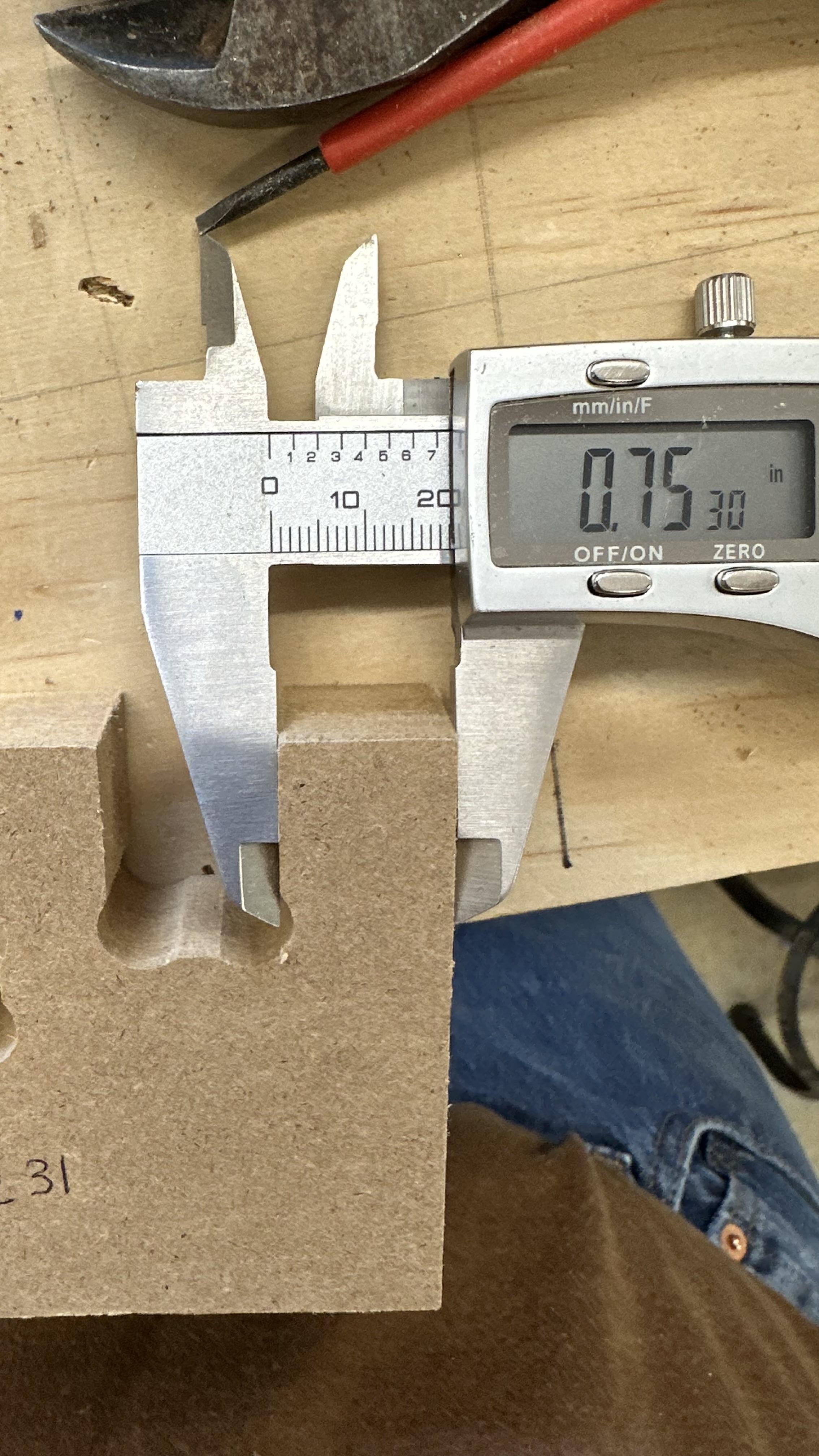
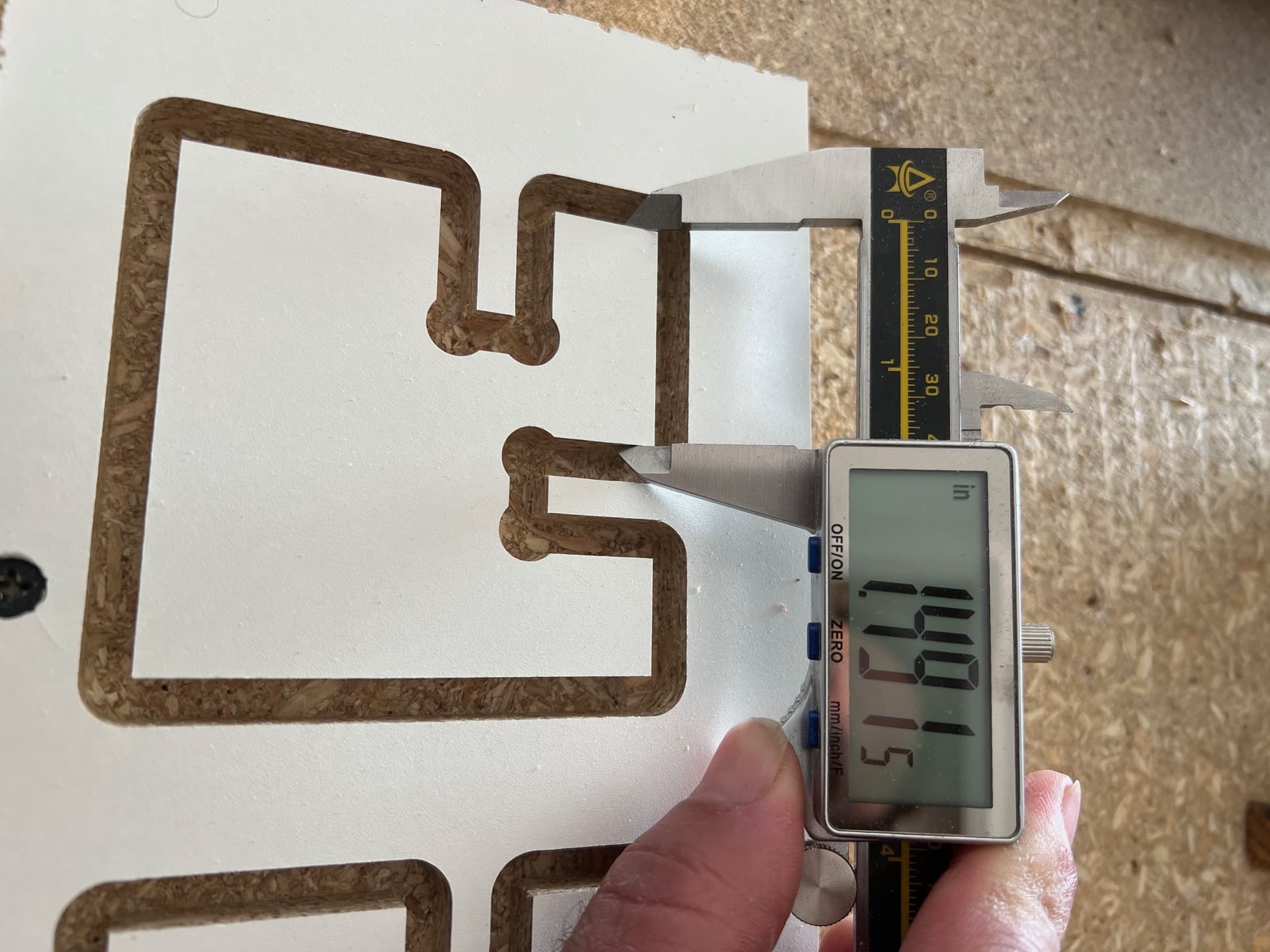
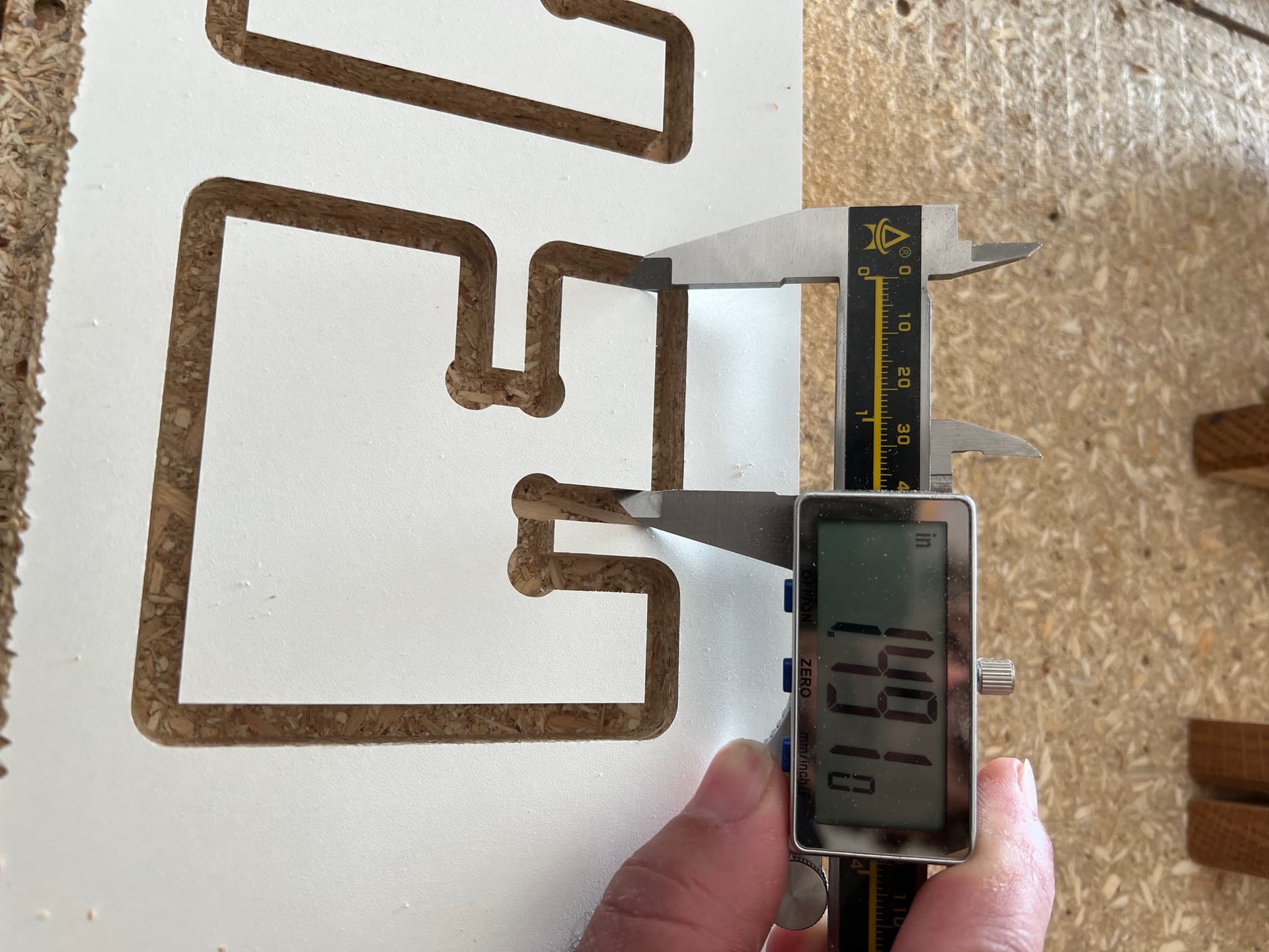
Measurements of the 4 parts with .75" dimensions plus overall size.
My results:
Material: 3/4" MDF
Endmill: SpeTools 1/4" 2-flute upcut
Feeds and speeds: 60 in/min (1524 mm/min), .25" depth of cut, 0.02" finishing pass at full depth. Approx. 14000 RPM on a Carbide 3D router (Makita knockoff). Holding tabs at the top just left of center, and on the right and bottom at about center.
Measurements:
.75" notch on the left is .735"; the notch on the top is .725" and both .75" “stubs” are .775. Overall width and length is 3.02".
Thanks - I appreciate anyone who’s willing to play along!
I found that I needed to define the tool size as less than the nominal tool size in order to get correct cuts. Your experience of having the slots undersize and the tabs oversize seems to mirror what I had.
The overall width and length would be “tabs” in this and the notches as slots. If you were to cut 2 pieces to fit together, they could not, since the slots would be smaller (0.725"?) And the tabs would be too big (0.775"?)
So you want the bit to cut about 0.025" more off. Assuming that you are using a finishing pass to get accurate results, you want to define the cutting tool as being 0.025" smaller than its nominal diameter. This will result in the CAM putting the tool 0.0125" closer to the defined cutting line, and removing that little extra material. This will result in dimensional accuracy and parts that fit together properly.
That’s curious. I did do a test like that in my other thread, making a similar adjustment and it helped a lot.
But it really begs the question: Why would I need to “lie” to the machine about the size of bit I’m using and why isn’t the movement of the machine correct in the first place? Is this a steps per mm issue or something else?
I concur, I had to do the same thing on a LR4, had to lower my end mill size even though it measures correctly. Which means outside cuts are now wrong, but pocket cuts are closer to correct. Is there a wider issue going on @vicious1 ?
That’s the darndest thing. Just did a test with the fake bit size (I used .231" because that’s what I had in my tool database from a previous test) and wouldn’t you know it, I get dead-on exact measurements on both tabs and slots.
I still think there’s some bigger issue at play here – a bug in EstlCam? A bug in the generated g-code? A bug in how FluidNC interprets the G-Code and commands movement? I don’t know. But there’s something – I can’t accept that this is “just how it is” and that everybody with a CNC machine knows you have to play games…
I always thought that was suspicious Dan. I’m fine if that works for you. But unless you have the wrong bit, that makes no sense.
Marty, those speeds look pretty fast to me. But maybe ok for a roughing pass. Have you tried it with a finishing pass? The number one piece of advice to hit a dimension is to use a finishing pass. If you’re using calipers, you have to use a finishing pass. If the machine is taking off too much material instead of leaving too much, swap conventional and climb milling.
You can do a simple square to see if the estlcam gcode is using your tool diameter correctly. It may be possible your tool isn’t cutting at it’s prescribed diameter. But otherwise, you’re adjusting for error without understanding where the error is coming from.
Yep, 0.02" finishing pass for my tests over the last few weeks. It’s a full-depth (.75") cut for the finishing pass (why? because I’m impatient…) - I don’t know if a shallower cut and multiple passes would make it better or not, but I can give it a try. Should my finishing pass be thicker? Guidance I’ve read suggests 10% of tool diameter, so I’m a little under that.
One thing I haven’t tried is conventional vs climb - been using climb all along because “everybody knows” that’s what you’re supposed to do…
.
Good idea, I haven’t really considered tramming up till now. But if it’s a matter of the bit not being exactly perpendicular to the table, I would expect to see “parallelogram” cuts, right - something other than perfectly square? I haven’t really noticed that, but haven’t looked for it either.
(it’s getting hard to keep my 2 threads straight at this point…)
My machine is full sheet sized and I recently checked X and Y travel at min and max, dead on in X over 1200mm and maybe .5mm short in Y over 2200mm.
Squaring is good, too - less than 1mm difference on the diagonals.
Tramming for me is only visable in deep cuts. It’s real viable when the angle makes the entire machine bind up and trash your work.
Checking tram is easiest doing 2 shallow pockets, one cutting x and b the other y. If the finish is smooth, youre good . If there’s a sawyooth texture, you’re not.
I kind of shake my head, but it works, and is consistent.
I have also measured the kerf from cutting slots, and it’s pretty consistent, a 1/8" nominal tool cuts a 3mm kerf. The ones from the V1 shop did this with 4 different trim routers, one of which is in a router table fixture. I get tight tab/slot fits with it defined as 3mm diameter. This goes from solid hardwoods (Oak, maple, walnut and birch) to plywoods to MDF, though not aluminum, where I get the expected 1/8" kerf. I don’t have a good explanation, just the observations.
Runout can also cause this. One time I had (I think) a piece of wood dust or something in the collet that made the cutting bit off-center, and it was pretty severe.
The bad part about this is that if you try to calibrate the effective bit size, then it changes every time you change bits.
It might be acceptable if you don’t have a need to fit tab A into slot B - and for most jobs on the CNC we don’t.
But (from my original results above), try taking a .750" piece of MDF and fitting it in a .735" wide slot. You might be able to jam it in there or force it in with a hammer, but it’s not a proper fit. But - as I’ve learned - once you figure out that you can lie to your CAM software about the width of your end mill, you can achieve a near-perfect fit.
And I understand better now that the “fake” endmill diameter is a means of compensating for all of the flex/deflection/imprecision inherent in the design and implementation of the LR4 – the machine simply isn’t capable of making a precise cut (even if it can make a “pretty good” one).
And that’s fine - my conclusion at this point is that the LR4 is wonderfully suited for cutting out doodads where dimensions don’t matter, excellent for making engraved signs, maybe even acceptable for doing carved inlays and certainly usable for cutting out cabinet parts that will be screwed together.
But for cutting out precise parts that need to fit together? Not so much.
I just wish someone had clearly told me 6 weeks ago that I wasn’t going to get the results I was after purely by making mechanical adjustments to the machine.