You need to build in tolerances, especially in wood. 0.12mm is absolutely tiny.
I never recommended a fake end mill. You 100% have to build in tolerances. Again 0.12mm is well well well within reasonable accuracy in wood even in very expensive machines. I have recommended several times you look at tramming if you want to chase zeros. Not once have you actually tried it. At this point you are defaulting to the machine being wrong. Please I urge you to look at Tramming for the third time. Error stack up is always going to be there but it absolutely can get better. I have not ever looked at any of your cutting parameters because Tramming is the next procedure in getting accuracy finer than 0.12mm in a 16mm deep cut.
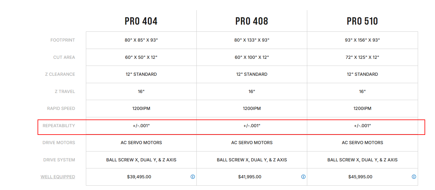
Again, before you blame the machine can we Work through all the calibration procedures to bring this up to YOUR standards. I will tell you Tramming NEEDS to be done to get above 0.1mm accuracy, and Belt Calibration NEEDS to be done to get above 0.1mm accuracy as the belts are not perfect. Understand you are asking for ABOVE Precision Machining. What Tolerance Is Considered Precision Machining? - Cheetah Precision
I am offended at this entire post.
Summary- Out of the box you built a machine that achieves what is consider precision machining by all normal standards, for well under $1000, and you have done ZERO calibrations to get you there. Instead of listening to the designer and doing some calibrations, you write a long post blaming the machine. There is no such thing as PERFECT in machining. There is always tolerances involved. "The standard prototype and production machining tolerance at Protolabs is +/- 0.005 in. (0.13mm). " from Protolabs, Understanding CNC Machining Tolerances
Let me remind you, you ARE already above this standard, with zero actual calibrations.
Even the next step up in Price even for DIY, PrintNC, only claims “The achieved accuracy with PrintNCs is in the range of 0.1- 0.03 mm.”, though this will depend on build quality too I presume
The issues I’m reporting are less about tolerance than accuracy. I fully understand that I need to include tolerance if I want parts to fit together. But for purposes of testing, I’m asking for a .75" slot and getting a .735" slot.
I’m not sure where the .12mm (~.005") number is coming from - I’ve typically been fighting .015" (.381mm) errors in my test cuts. I would have been pleased as punch to get .005" accuracy at any point.
You didn’t, but others have. And that’s the only change I’ve made that seems to have made an appreciable difference.
Tramming is on my list, but it’s going to have to wait until I get the new torsion table built. Conceptually, however, I’m not convinced that tramming is the silver bullet - if the mill isn’t quite perpendicular to the work surface, it’s just going to make not-quite-perpendicular cuts.
You’ve mentioned “belt calibration” a couple of times now but I’m not finding anything in the docs and no obvious threads in the forum that explain what the process is. Where do I find the details?
I don’t think that’s an accurate description at all. I’ve done all kinds of calibrations, just not tramming – I’ve replaced belts, replaced the router, adjusted the belt tension the best I could, tightened and adjusted the core travel on the gantry, etc. etc. I’ve tested and re-tested squareness and movement and all of that stuff.
And I don’t agree that my LR4 achieved “precision machining” out of the box – if it had, I would have gone merrily on my way and not needed more advice.
I replaced my belts a few weeks ago with fresh ones from V1, then checked movement in X and Y. Zero (or certainly a lot less than .5mm) discrepancy in X over 1200mm and about .5mm in Y over 2200mm. That seems pretty good to me.
My belts are tensioned using the TLAR* method, as I don’t have any tools that could make it any more precise.
Why? Tramming is setting the router to your beam, it has nothing to do with your table. If you want better than 0.1mm you need to tram your router, surface your table, tram your router again, and surface your table again.
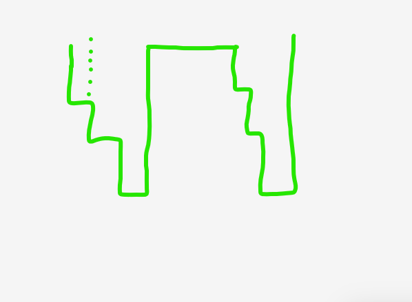
Think about that for a second. Imagine you are cutting out a square.
The dotted line is where the part should actually be.
I am not making things up to defend my proven designs, I am trying to help, genuinely.
I designed this machine, I have been working with these machines for more than 10 years now. I have asked about tramming and belt calibration. Replacing my belts with more of my belts and switching routers would never have been on my list of suggestions.
I am trying to help you but you are being combative. I gave you a link for a tramming tool that prints in about 30 minutes, and takes a few seconds to see if I am wrong or right. Or you can keep telling all of us here how bad you think this machine is that we all keep telling you it can be better.
That is far better (3x) than I have tested with any belt I have in stock, but it very well could be the case I do not test every batch.
Belts should be just above 7lbs tension as per the instructions, it is not much. If you followed the directions and they do not make a sound when plucked, you are probably close enough.
Please make a test cut of a square, 19mm on each side (~0.75"). Cut it to a depth of 2mm, with a 0.4mm finishing pass. Let’s see what numbers you get for each side. This will minimize tramming issues in the test.
Take the router out of the CNC, use the router like regular, cut a shallow slot, ~2mm. Measure the width, that is the effective diameter of your endmill. The CNC can not make the endmill cut more narrow than it is, I don’t have SPE end mills to test with.
I never saw any mention of slot width, I have just been following the part dimensions.
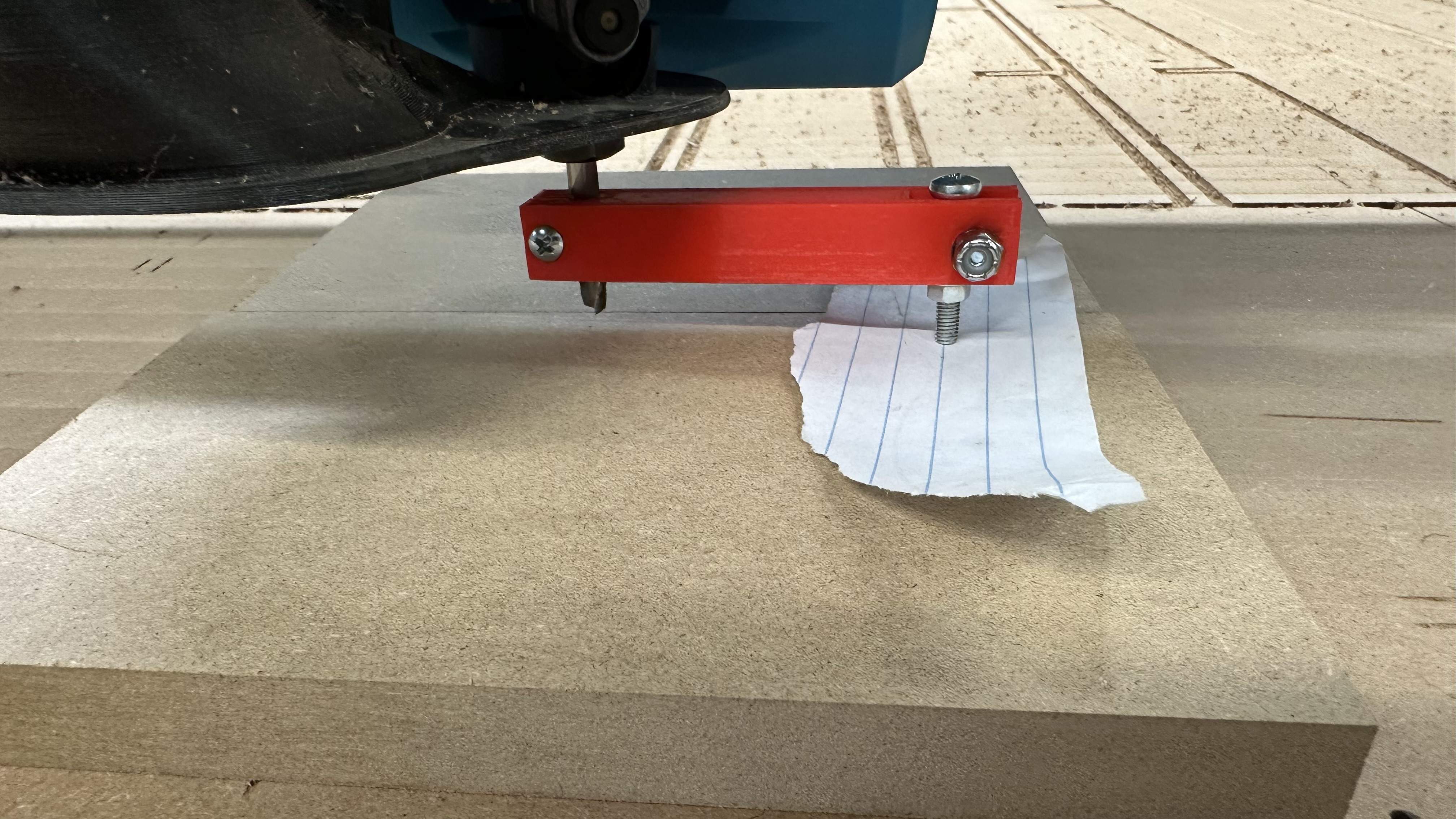
Ok. So I surfaced a section of my spoilboard, and measured the tram distance, using a piece of paper under the screw (kind of like I’d do with a 3D printer to calibrate the bed) and looking for where it grabs the paper.
X axis is maybe 0.1mm off from left to right, with the right side being just a touch lower.
Y axis is about 0.7mm higher in the back than the front (that is, the screw was .7mm above the surface in back compared to front). And that measurement is borne out by the horizontal lines from the surfacing run - my 1.5" surfacing bit was clearly cutting a tad deeper on the “front” side.
So I’ll add a shim at the back of the bottom mounting ring and surface again and re-check the tramming. Will report back either this evening or tomorrow.
Can you recommend a single-flute bit with a 3/4" cutting length? I’ve got a few Kyocera 1/8" single-flute bits but they only cut about 5/8".
Terminology may be getting in the way here. By “slot” I meant a notch, like in my drawing above, that another part would fit into – not a single cut to determine the width of my end mill.
After shimming the bottom bracket at the mounting holes with .015 worth of brass shims, my surfacing pass looks nearly perfect. I’ll double-check tram tomorrow and do a test cut to see how much better it is.
@vicious1 - thanks for the bit recommendations; I’ve ordered a few of each and look forward to trying them out.
Re-checked the tramming today after shimming and re-surfacing last night.
I measure less than 0.2mm on Y from front to back and maybe 0.1mm on X from left to right. Don’t think it’s going to get any better than that.
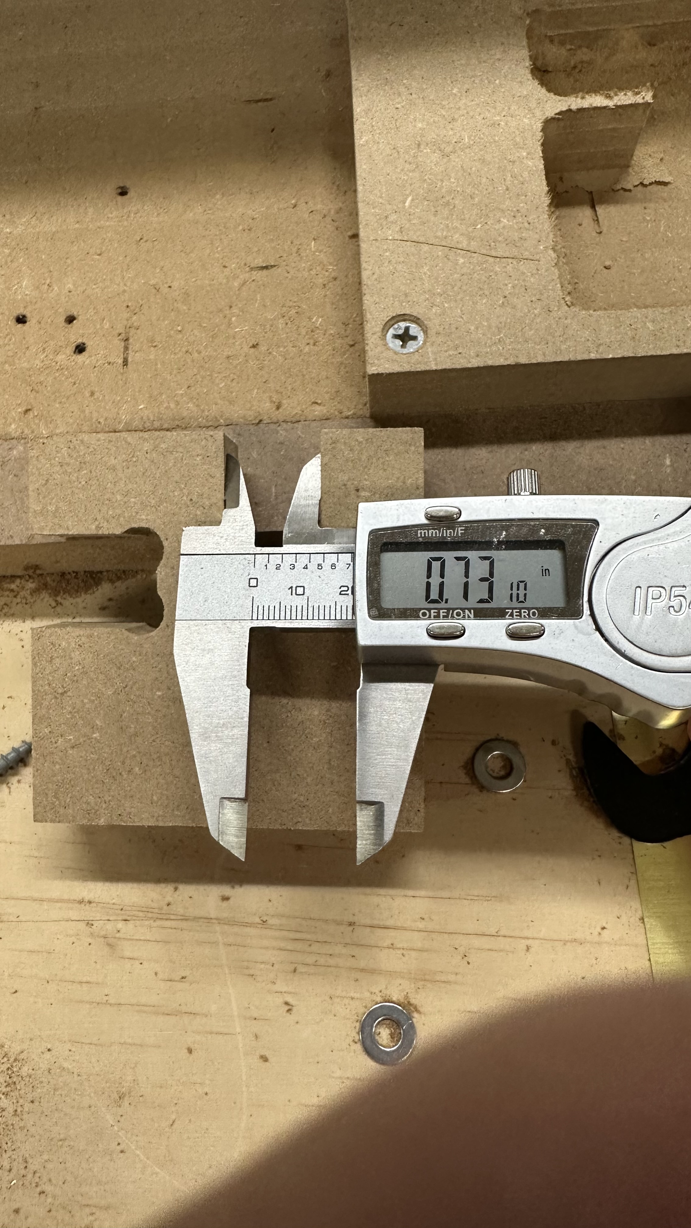
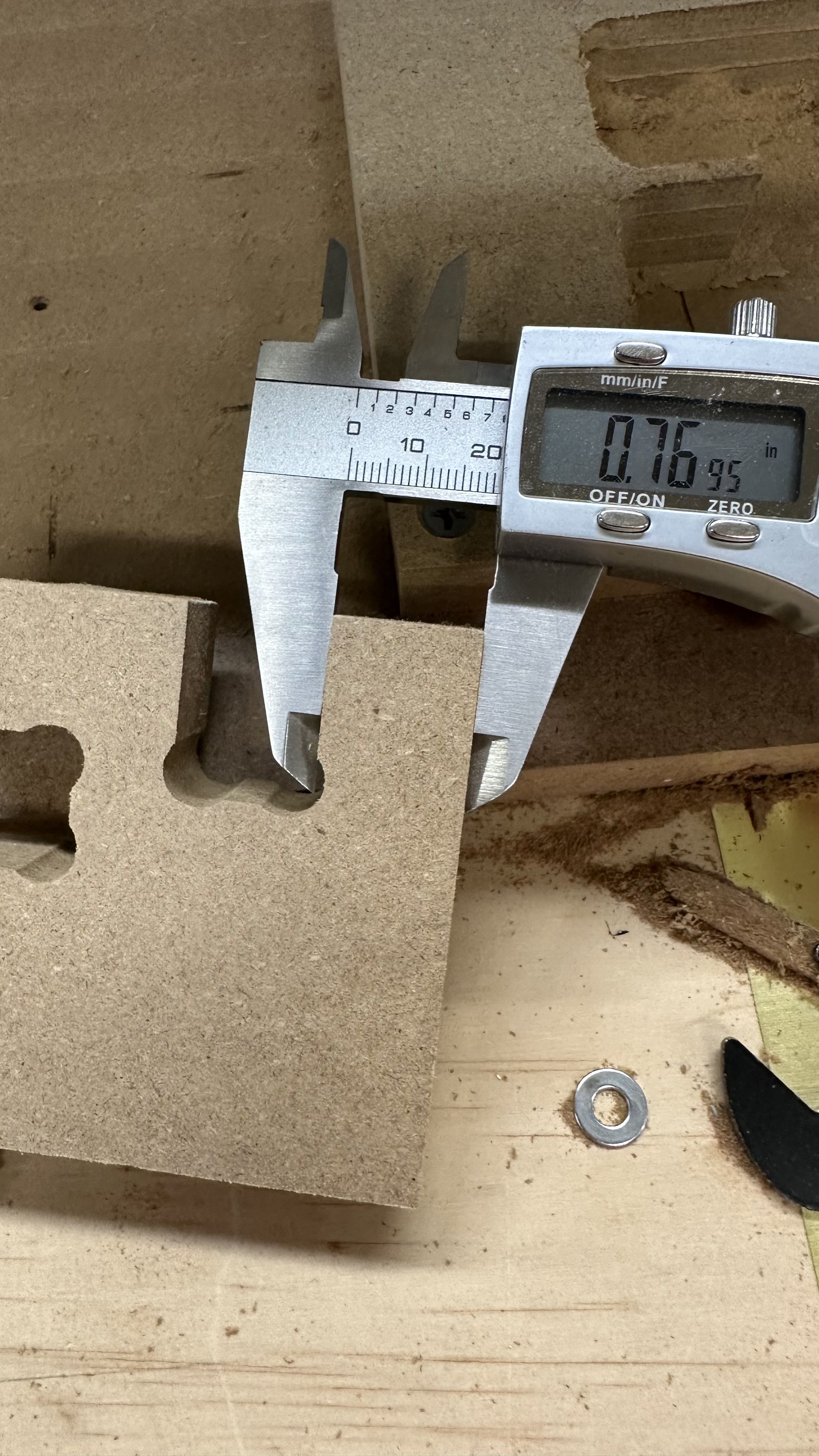
Ran another test cut using my drawing from above, in 3/4" MDF with a SPE Tools W03001 1/4" “O” flute up cut end mill. 60in/min feed rate, .25" depth of cut, 0.05" full-thickness (.75" ) finishing pass and about 14000 RPM.
No difference in final results: slot width was still about .730" and tab width was still about .77"
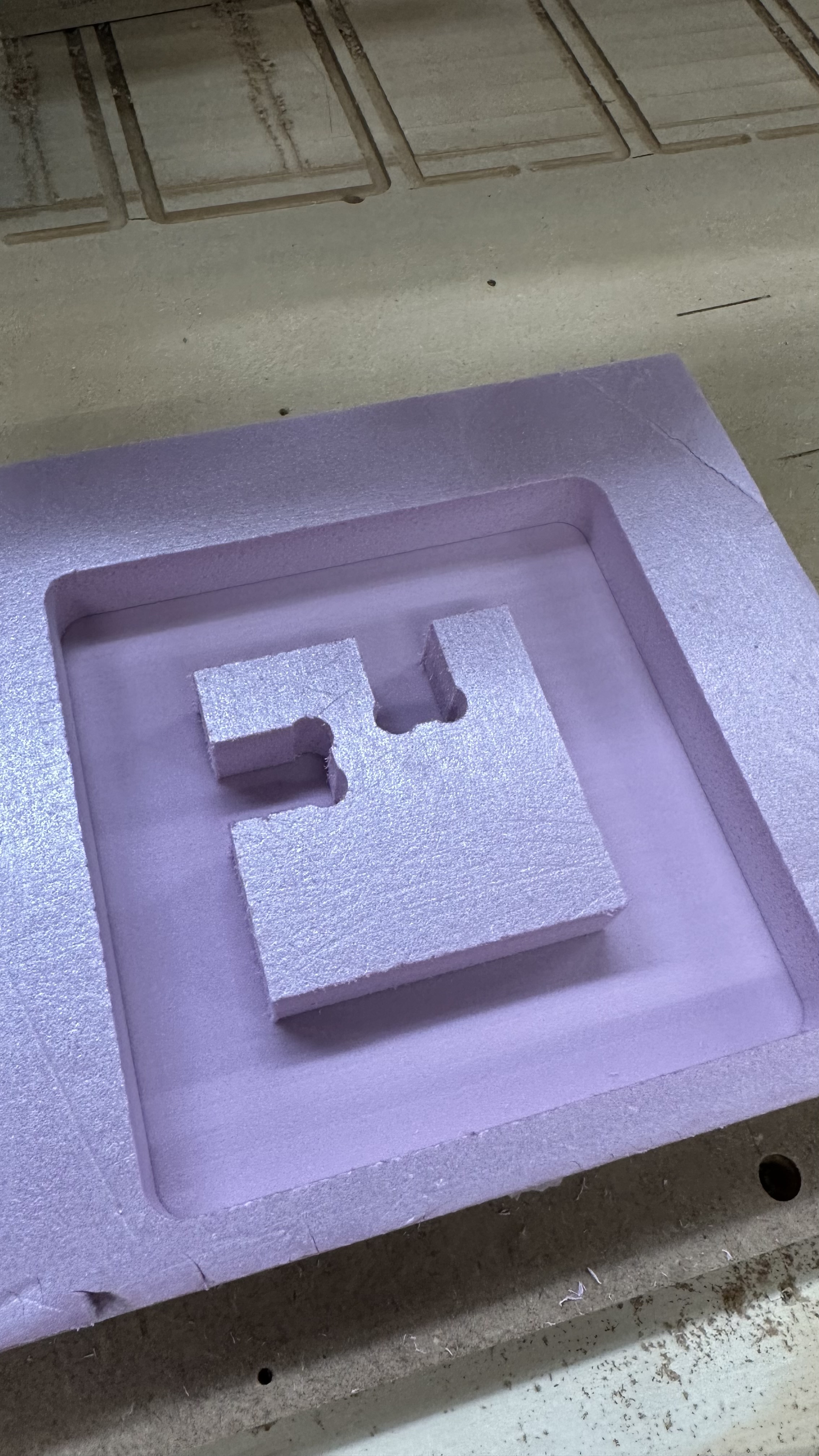
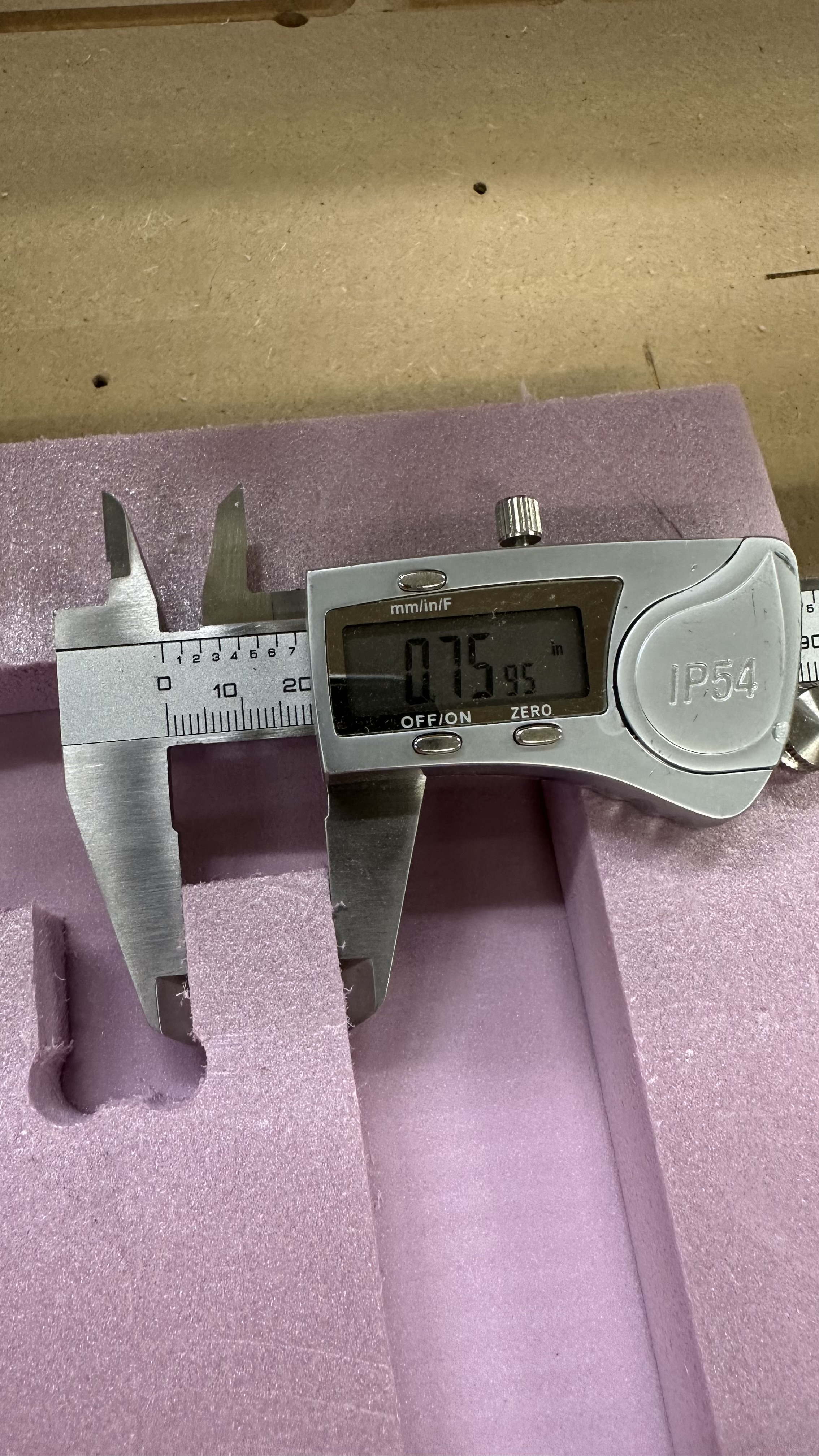
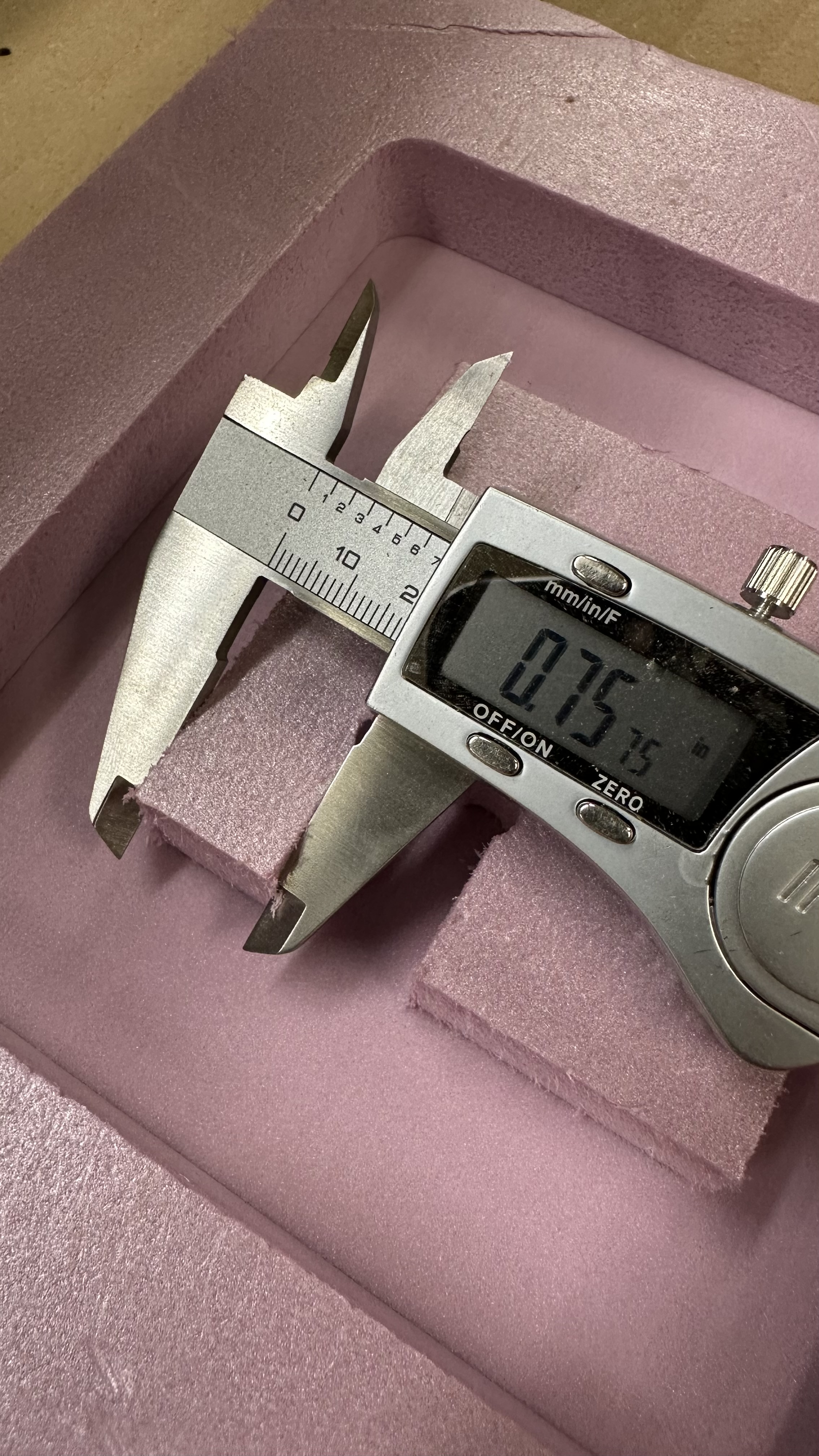
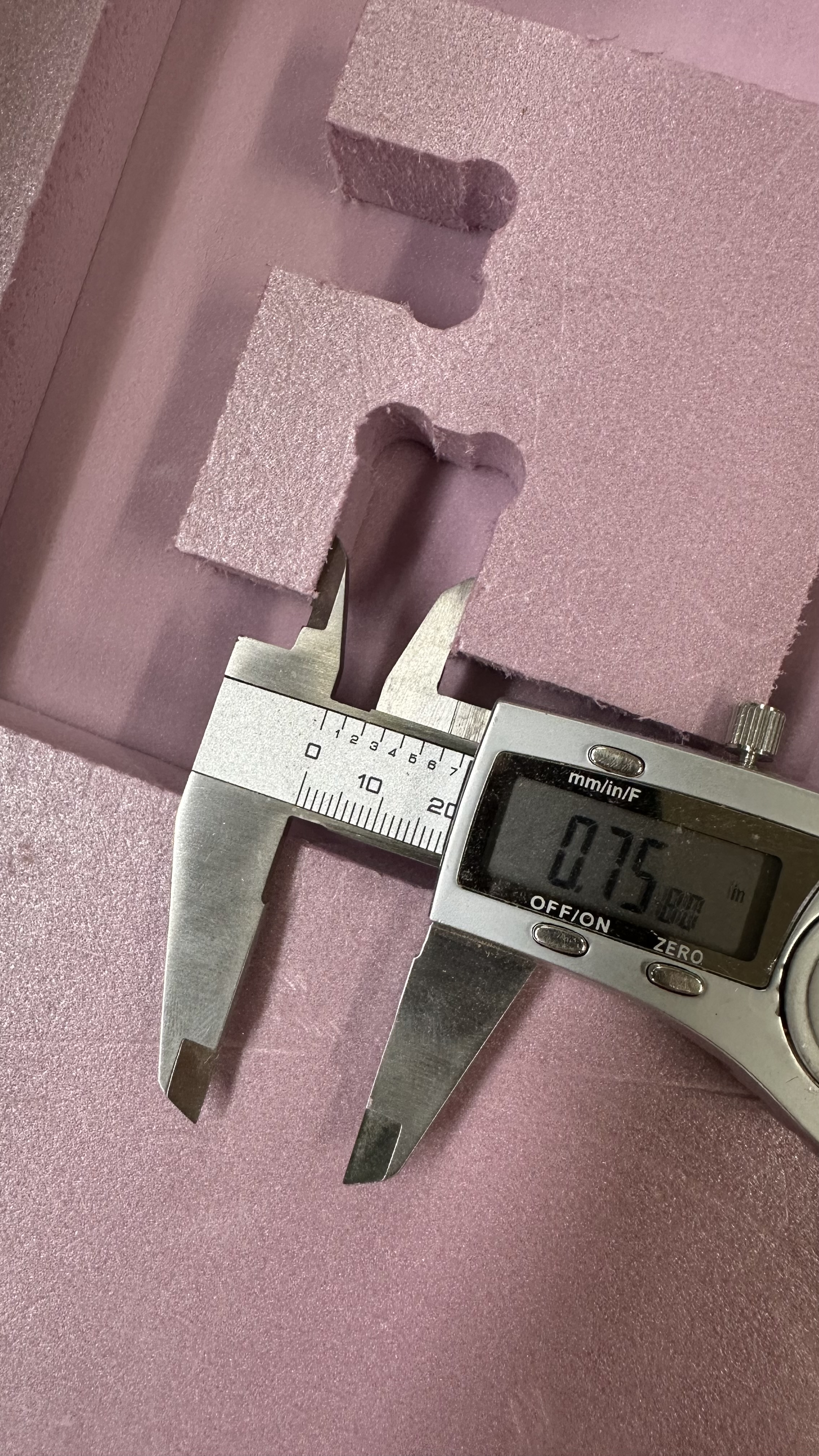
Then I ran another test in 1.5" extruded foam, same feeds and speeds but altered the program slightly to do an “island” cut around the test drawing. Same 0.05" finishing pass and all other parameters the same.
It’s hard to measure inside gaps in foam, but it looks like the cuts were very close to what they were supposed to be - a tad oversized, actually but again, it’s hard to measure foam…
So it seems to me that the issue at this point is all about flex/deflection when cutting. But I don’t have any ideas what else I can do to improve it. Shallower depth of cut? Slower feed rate? Different RPM? I feel like the parameters I’m using should be pretty reasonable - 60 in/min and .25" depth of cut
How are you securing the piece to the spoilboard? I see that you have screws but are you using tabs in your CAM or screws in the part that is cut out? If you are using tabs, are you using enough? If not, it’s going to move. I agree that a video may be helpful.
That is kinda fast. I ran 3/4"mdf cuts for a year straight daily and I don’t think I went that fast. Deeper and slower. With a single flute.
You are also using a two flute so it can get clogged up. your RPM should be as low as possible. You might need to move that fast to keep them from burning.
The other thing you should try doing is increase your finishing pass width a little bit, and slow down the feedrate. Your dimensions come from the finishing pass.
You can go fast with roughing if you dial in your finishing pass right. Do a couple test cuts with a .2, .4, .6, .8mm finishing pass at like 15mm/s. When you find the winning combo start increasing the speed of it until you lose the tolerance you need.
I ran two tests just a few minutes ago - one with the same DOC (.25") but 20in/min feed rate and another with .125" DOC and 60in/min feed rate. The results were pretty much the same. I didn’t try slower and shallower at the same time, but can put that on the list.
The tool is seated in the collet right up to about where the flute starts. Definitely not more than it should be. For the current tool, that’s a stickout of about 1-1/8".
I can’t detect any movement in the core, but if I push the bit along the Y axis, the entire machine moves a little bit, visible when looking at the YZ assemblies. I can’t tell what’s allowing it to move, or if I’m pushing more than “lightly”. Here’s a video showing the YZ assembly moving: https://www.youtube.com/shorts/X51O0CT7A4o