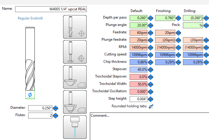
What depth of cut should I be using on the finishing pass? I’ve been using a “full depth” (i.e., 3/4") finishing but haven’t seen any guidance one way or the other.
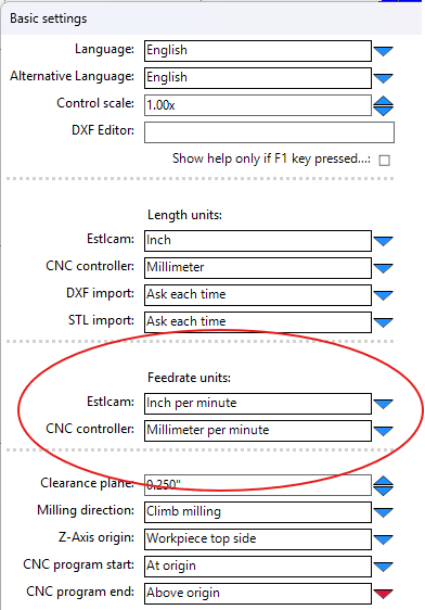
Check me on EstlCAM settings – I think I’ve got the right combination under general settings (I use Imperial units for display because… I’m a 'Merican…)
I also had similar results with my MPCNC. To correct this I made the bit a larger diameter in ESTLCAM to make up the difference. All my cuts are accurate now. When I was testing all this my assumption was that the router and collet weren’t that accurate.
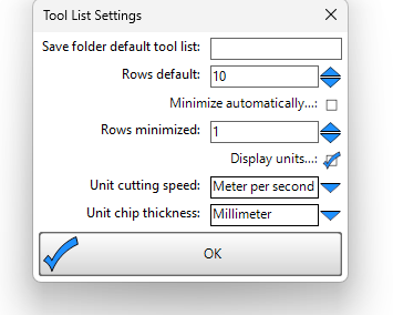
You can change your chip thickness display to something potentially more useful… I have no idea what chip thickness in percentage means when I’m looking at it.
Another test, 25 mm/s and .26" DOC, then .02" finishing at 10mm/s and .26" DOC, all with the router on the slowest speed setting. Might have improved the results by .010" at most, so I guess that’s a little bit of progress.
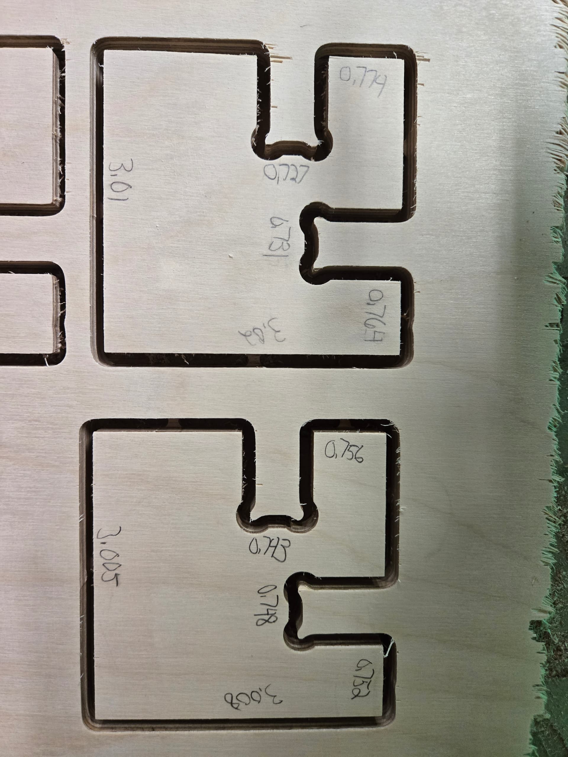
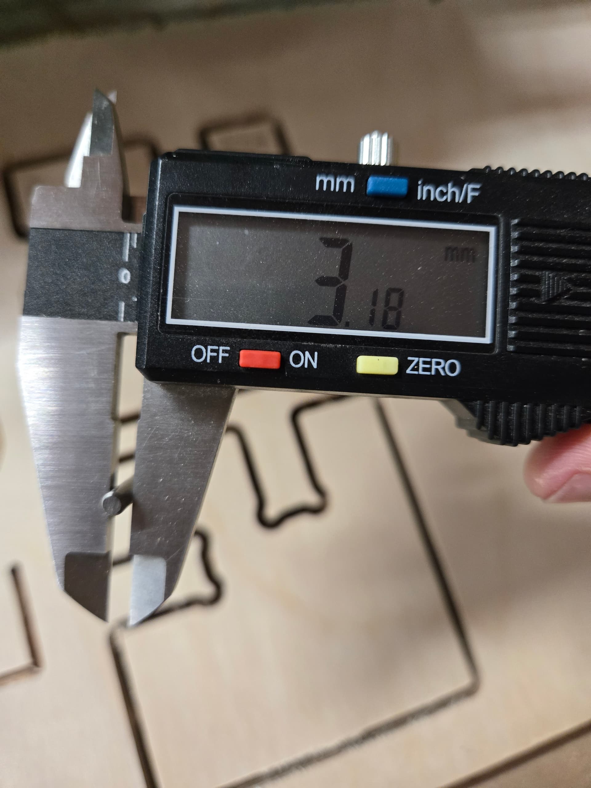
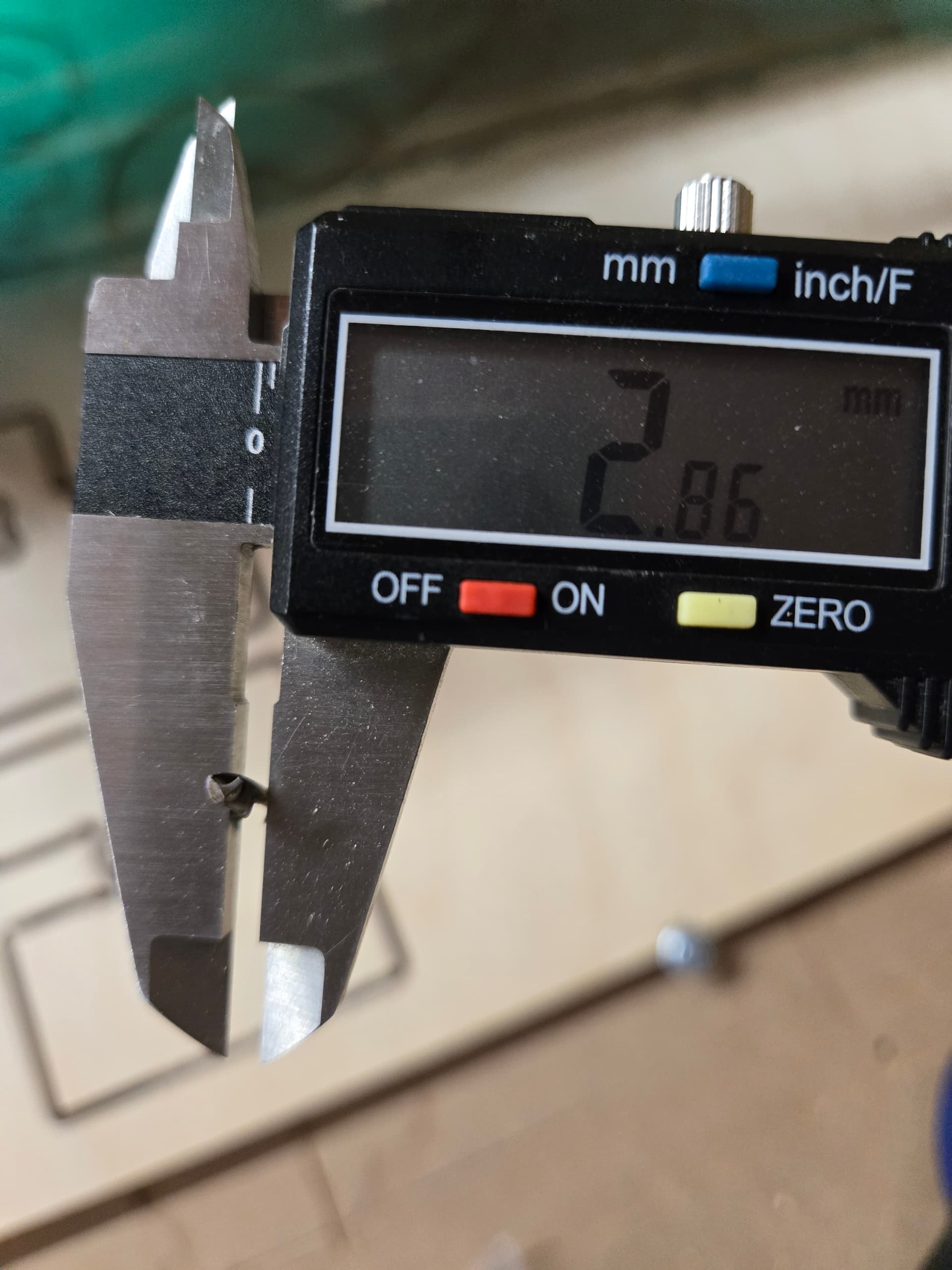
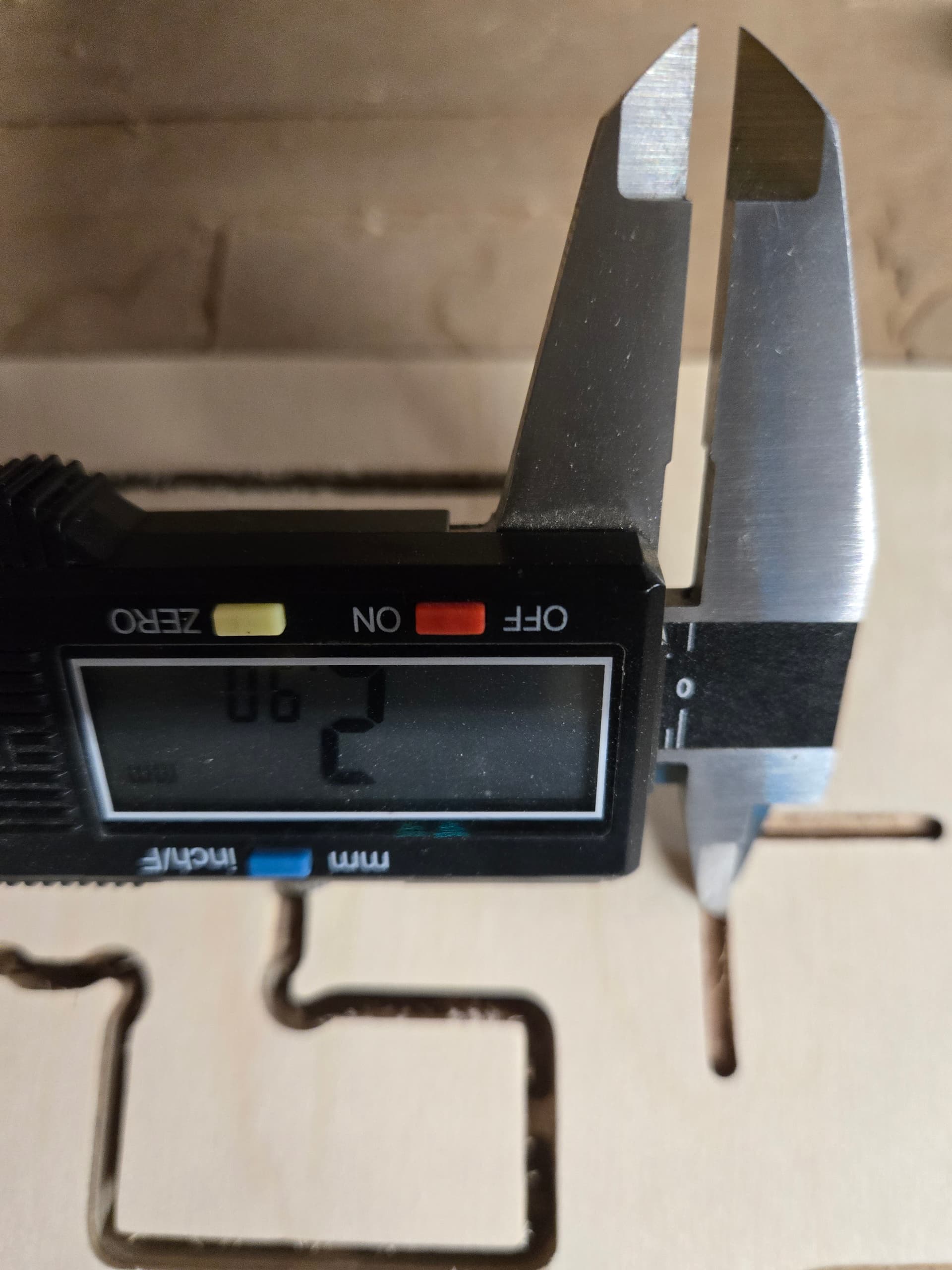
Alright, curiosity got the best of me so, I gave this test cut a try. Note I have an LR3. First round, I whoops and added the finishing allowance but forgot to set the tool. So, those numbers were bad since that means it adds that buffer but doesn’t remove it. Second round, I fixed that and saw very similar results to Marty. It’s an 1/8" bit and I had it in CAM as 3.18mm. This is the standard 1/8" bit from the V1 store. When I measured the shaft of the bit, it was 3.18mm. However, when I measured the cutting portion, it came out around 2.87mm. I then cut a slot and measured it. It was around 2.8 to 2.9 mm (a bit difficult to measure). So, I updated the CAM to treat the bit as 2.87. Then it came out much more accurately.
So, I didn’t lie about the bit size. A difference of 0.3mm matters. I measured it and the slot it cuts which is not the same as the shaft of the bit.
It makes sense in my head that the cutting width is smaller than the shaft of the bit. I’m assuming these bits are made out of a piece of 1/8" carbide rod. So, when they add the cutting part and sharpen it, it would be smaller than the shaft.
Well shoot, makes sense but dang. Can you show me what bit it is. I had some off the shelf ones then 6 months back or so I started getting them custom made. I really hope the custom ones are not that far off.
The one without the collar is the one I used. It’s older than the one with the collar which it looks like I bought about a year ago. I never looked close enough to notice they were different.
I still have some > 1 year old 1/8” V1 bits in their PLA printed V1 carrier if you were to want one back to compare. I’m not able to get to them before tomorrow at the earliest.
I did at one time have some cheap cutters that I’ve noted did not cut the advertised size.
I always naively assumed everyone does like I do- which, as Ryan requested REPEATEDLY in this thread, is to cut a shallow slot by hand and measure it.
I’ve also had drill bits wobble in particularly hard material (in my hand drill) and they cut a triangular hole that is smaller than the shaft size of the bit. The same bit would probably cut a larger hole in a drill press (closer to the size of the shaft). I wonder if the bit is flexing (or the machine is flexing) enough so the bit isn’t cutting the full width at high load.
This makes sense to me. You all know I distrust measurements and I don’t like calibrating the belts (for example). The key here is that the measurements need to be easy to do correctly and hard to do incorrectly. Calipers give us this sense of confidence and then we trust the 0.01mm it says and extrapolate out to 1200mm. It would be very easy to make a mistake in this measurement and then be worse off than trusting the manufacturer spec.
The design Marty is suggesting is a good calibration object. It should only be trusted on a trusted machine. I would trust Ryan to run that shape on a new type of bit and then put the results of the test on the box of that type of bit. The measurements here include errors from the machine as well as the bit.
The manual straight line test could be useful too. But I would ask that we include running it on a straight edge so the result is easier to measure with calipers. And it shouldn’t be a full depth cut (a dado, not a through cut). The result should be pretty easy to measure. Without a straight edge, there may be a slight arc or wobble that would make the measurement smaller than a single hole.
Ultimaltely, I like the slot cut as a first test and Marty’s dxf as a confirmation. It should tell us a lot about the machine to do the DXF test, do the manual slot test, then adjust and do the DXF test again.
There are definitely different classes of bits. I’m guessing whiteside bits will be accurate in that dimension. But I don’t want to spend $50 on each bit. I know I’m not alone. I would rather a bit that cuts well, accurately, and needs some adjustment in CAM for sub $20.
I owe @SupraGuy an apology. He brought his experience and simple solution right to the front and I was too harsh on it. The bit diameter in CAM needs to reflect the shape cut by the bit in the material. I made the wrong assumption that the manufacturer’s spec is more accurate than the measurement from a gcode shape and you were compensating for another error by changing the bit size. Sorry.
I also owe Marty an apology (or maybe just respect) for bringing up this topic and sharing this test file. I didn’t take it seriously enough and we were too focused on keeping the status quo solutions. This test object seems like the perfect test to calibrate bit size on a machine that is well constructed.
I said many many responses ago to the OP: measure your bit, bits comes really off for some brands, cant speak about germany but the majority of stuff we get from Amazon its like the same we get from AliExpress.
0 flutes (spiral) wont measure correctly by hand. You have to make a cut (preferably using some ramp lead in)
Get some straight cut bit, do a couple of slots and measure if the cnc is doing what is supposed to be doing
To be clear, and as @jeffeb3 said above, measuring bits and cuts can be a bit tricky.
I had cutters the produced a slot which was more narrow than I measured the cutter itself (single flute). Most likely root cause is I measured it wrong. “You did it wrong” is always a plausible reason at least for me. That of course include “You built it wrong.”
I still say it’s better to measure the resulting slot (cut) than the bit as it’s the cutting results that matter to the user, and is an explanation for why “misconfiguring” the CAM tool size can produce quite good results.
I agree with Jeff that the DXF used here is a pretty good benchmark. Maybe add an outline “+” cut in the center somewhere to facilitate measuring the slot in X and Y and with each direction of motion for each axis.
Very interesting topic.
Edit: @vicious1 this discussion hints about a need for more elaboration around “setup, calibration and use” in the documentation. Maybe even with a sub section detailing why and when it becomes necessary to do things like steps/mm calibrations, when and why tramming affects the work.
I’m not good at writing that stuff up. We have users who can crush it with machine capabilities and others like myself who struggle with the machining operations (using) of the machines.
I agree that measuring the bit is tricky. I tried to measure the widest part but depending on bit design, that might not work.
I just cut the slot to measure by jogging. It wasn’t very deep. That’s a bit tricky to measure too. You’re pushing the “sharp” part of the calipers into soft wood making it pretty easy to push too hard.
I have no issue with bits costing $5 requiring some calibration. For many things I cut, being off by half a mm does not matter.