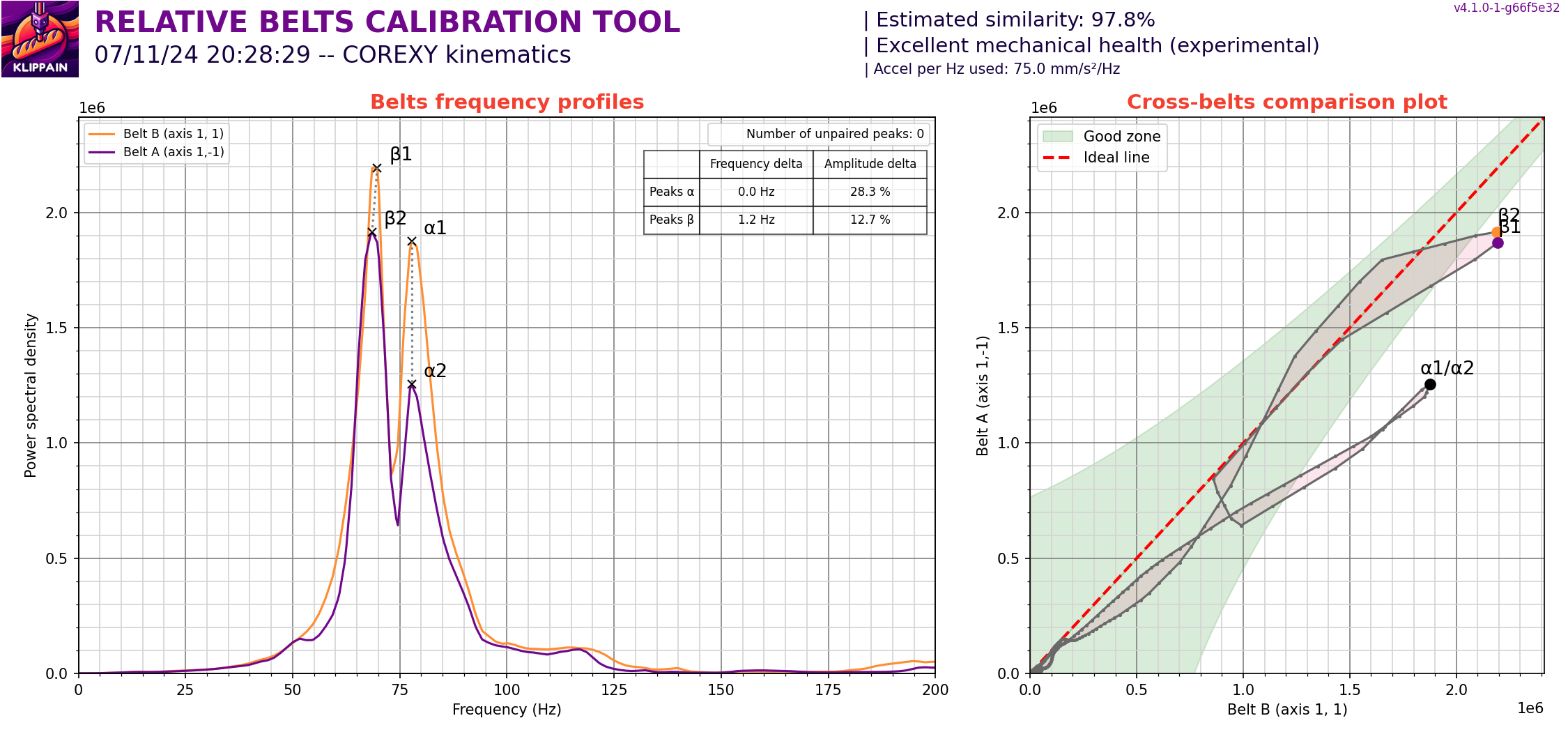
96.8 is amazingly good I would not take them off.
1 Like
1 Like
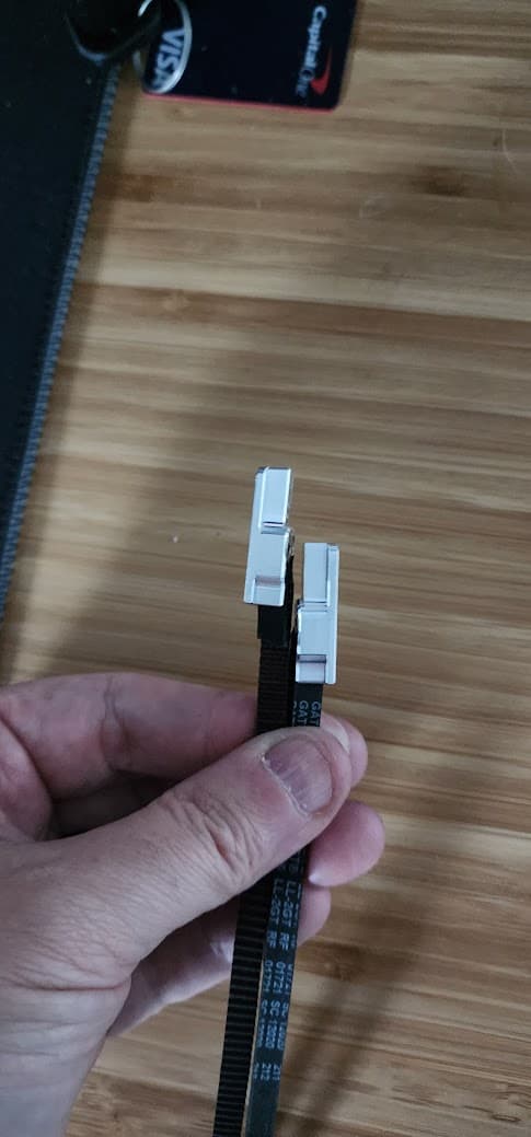
Yeah they make a MASSIVE deal about them being exactly to the tooth the same length. In some ways it makes sense in others I’m not so sure.
Interesting, I never even considered belt lenghts could be an issue at all.
I bet they are vastly off on my corexy machine as I didn’t pay any attention on this point whatsoever.
This thread is really interesting to follow
Did it make any difference in your ripple?
3 Likes
not sure yet. Was too late to try a test print last night.
bed is heating up now.
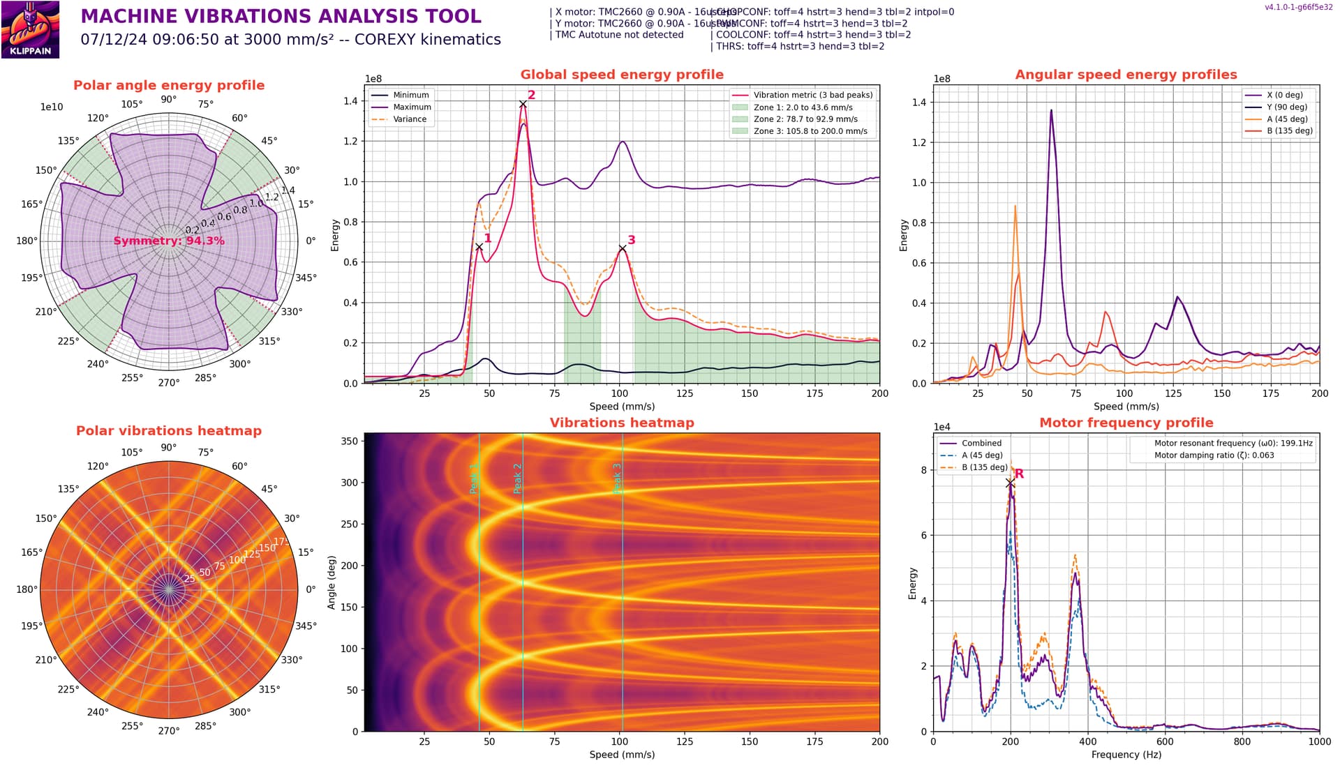
I need to do another vibration test, but won’t be able to do that until after 5. Shaneh’s office is below mine.
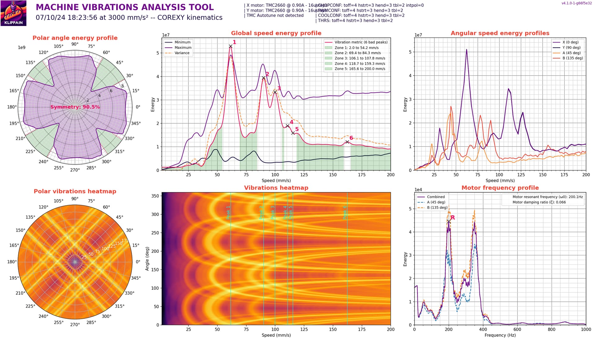
so run the test, then set your print speeds in the green areas.
Running a calicube vase mode at 80mm/s.
Nope, still has ripple! ![]()
Suuuuuper faint though.
To be fair, that question was only out of hope that I had done something wrong…
I also had tried to get my belts the perfect length, and was printing in the green zone, etc. etc…
So I was hoping it made yours better for you… but it didn’t help me
I still see artifacts on some of my prints, but not all. But I also haven’t printed a cube again… ![]()
2 Likes
I figure as long as my mechanical parts fit, I’m not going to worry too much about ripple. I can’t feel them, and have to move the part around to get the perfect light to see them.
All of this is mostly me being bored, and trying to get my printer quieter.
Shaneh was between meetings, so I did another vibrations test.
1 Like
I agree… unfortunately I was able to feel mine, and they weren’t so hard to see.
But I’ve left it alone for a bit, and I’ll revisit when I get some other things finished and out of the way
1 Like
So, I haven’t really been trying very hard to test this at the moment, but I thought this might be an interesting data point to share.
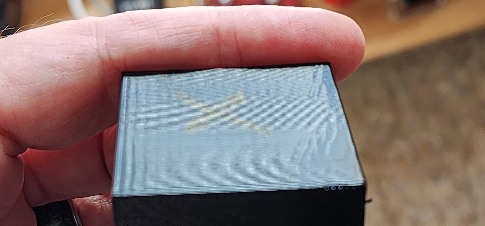
Since my last updates, I have replaced the 0.6mm nozzle on my printer with a 0.4mm CHT nozzle.
I ran a test yesterday, and it has changed again.
This was printed with a 0.4mm nozzle at 0.16 layer height.
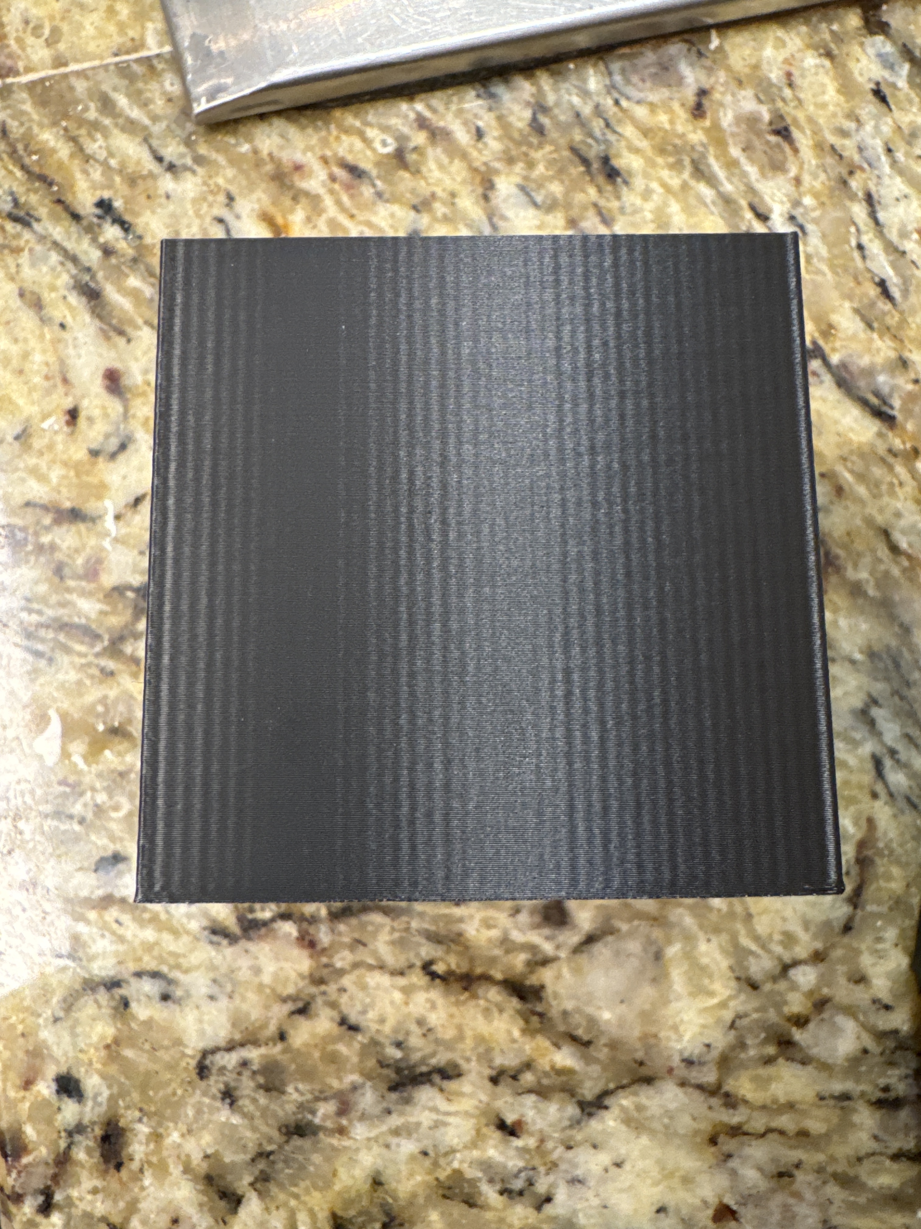
This ripple is much closer together than it was before I changed the nozzle
1 Like
Well, if it was extruder related a smaller nozzle would mean longer extrusions per micro step so the ripple would be further apart I would think.
If it was linear bearing related, it should not change.
This is crazy
1 Like
Printing faster (same flow volume)?
What face is that X or Y?
1 Like
In this case I was printing a little slower than most of my previous tests to try to match speed with my Ender, so speed and flow was slower.
I couldn’t tell you, but it looked pretty consistent on both I think. The cube was turned at a 45, so not aligned on X and Y, but on belts paths.
Which is also different lol…
Because when I first started this thread it was only on one belt path mostly…
2 Likes
I wonder if someone else could slice a simple model for you (or you for them). So that identical G-code is being run. Then two machines could execute the same file. You might have already tried this. I can’t generate and run the gcode as I have a bed-slinger type.
1 Like
we’ve done that.
I have also run models that Ryan has sliced.
The thing is, it’s not all models. I have printed some things that look great…near perfect
4 Likes
Is a bad model always bad or does it sometimes print fine? In other words, are you saying that some models never have the ripple and some models always do? Just thinking if it could be an external factor, e.g power/noise etc. Sorry I have been reading this thread with interest, but I’ve lost the… thread.
The models where I have seen it, are always bad.
The Scoop
the ringing tower test for resonance compensation
Right-Click on build plate and add a box.
etc.
I have seen it on large flat surfaces, as well as on some curved surfaces.
It’s all kind of scattered because I went through this once by myself before saying anything
I went through it once just talking to JJ on the side
Then again through this thread, and have been through so many iterations that it’s hard to even keep it straight in my head anymore lol
The real issue is, none of it was extremely scientific. I’ve tried lots of things but the differences between all the tests and exactly what changes what is not well-gathered or well documented.
Changes were not always well-constrained to be one at a time, and I was also fighting other issues with my printer at the same time, and rebuilt it twice during the course of all of it as well.
The one thing I know that was very repeatable, was the initial scoop I printed, as well as a plain box.
So I open PrusaSlicer, right-click on the build plate, add a square. Resize up to 60 or 80mm. rotate it 45 degrees so each face is aligned with a single belt’s motion. Turn top layers to 0. Perimeter count has been tried at both 1 and 2. 0% infill. 0.5mm nozzle with 0.2 layer height.
I don’t think there has ever been a case where that did not show it.
Increasing either the layer height or speed or belt tension has all had some affect on it to make it less visible.
I have printed the same model on my Ender 3 using the same setup in PrusaSlicer and it comes out fine, with no visible artifacts.
That’s about the best I can do for a brain dump summary at the moment lol.
It’s a very frustrating thing especially since it is not consistent across all prints. If the same pattern appeared on every single surface throughout all prints, I feel like maybe it would be something more traceable.
Having it show up just “when it feels like it”, to me, is worse for tracking it down, but better for being able to actually use the printer ![]()
4 Likes
Slice an always bad file in Cura and see how it changes.
Wouldn’t that mean that you need fewer steps per distance traveled, so if it is extruder related then you should see them be closer together? EDIT: What I mean is that as the flow is happening, you ‘see’ the impact of each small step in a more pronounced way with the smaller nozzle.
This looks like there is a flow-related mode here where the line width is varying because flow through the nozzle is varying. Different outer shells may have different behaviors depending on what type the slicer decides they are.
1 Like