I got in. here is a screenshot. Worth a try???
** Although it looks like his waves were up and down and not side to side like yours **
I got in. here is a screenshot. Worth a try???
The waves definitely are different, and the solution/advice he points to is buried in a facebook group that isn’t public.
I think it seems a little too specific to something else on his machine, I think, than the issue we are seeing which has surfaced across 3 machines with different settings, rails, extruders, power supplies, etc.
In the beginning I thought it was a bad part on my machine, but I have now replaced all of them.
With this showing on more than one build, it feels more and more to me like something intrinsic in the design, but I don’t know what…
Something that carries vibrations easily maybe? I’m really out of my area of expertise to even venture a guess, but I’m not a lone datapoint anymore.
I don’t know what else to test yet.
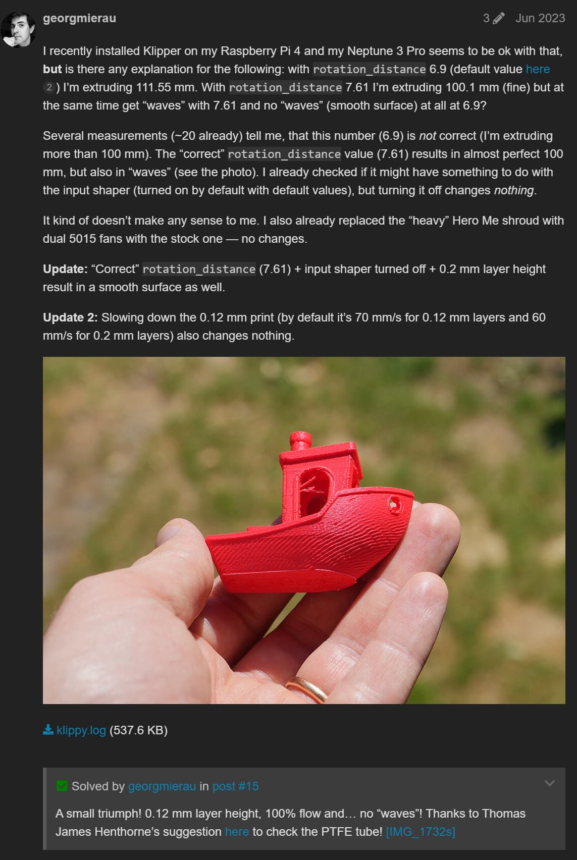
It sounds like the guy above had a PTFE tube problem. I can take my filament out of the sensor and PTFE and feed it directly and test to be sure
Or Firmware, If the Railcore builders are seeing it as well. That post is getting me thinking about it more. Different extruder steps per millimeter were working for him. My printers are pretty busy right now or I would be testing this.
He had a PTFE problem but it isn’t clear if that was the problem. It looks like he was print without waves before that.
Interesting to try input shaper off, or Pressure advance off, from that post.
I did that before I left. I’m pretty sure 40mm/s test print I did had both of those off
Edit:
I don’t know if I posted the pictures, or which ones they were, but at 40mm/s with none of that on, it was still there
I have 2 other corexy printers running klipper and neither of those have it. One being the V4 and the other being my Ender5+
But if you still think it could be firmware then you are the only one of the 3 of us that can test that lol. Me and @Michael_Melancon are both running canbus and that’s not supported by marlin AFAIK
Yeah I’m not buying that as the issue. None of us have any PTFE tube after the extruder to be able to clog.
Maybe there is some kind of bug in Klipper or the slicer(s) when calculating how to command the extruder for flow, which manifests itself in slight variations in delivered flow rate to the part, which then would manifest itself as very slightly varying extrusion with across any given extrusion segment.
I would say, maybe, if it was more confined to a single set of parameters.
But it’s hard for me to come to grips with it being a firmware bug like that since it was seen across a wide range of flow rates from 4mm3/s all the way up 17mm3/s
It was across both 0.2 and 0.3 layer heights, from 40mm/s up to 130 mm/s.
If the flowrate calculation was that finicky, it seems like it would affect a much larger range of Klipper users.
Slicer? maybe.
But JJ, Ryan, and I use different slicers, and have 3 different sets of settings, and have all seen it as well.
Now… that being said…
I decided to quit worrying about it for a bit and print a few things I needed to print, after burning more than a half a spool of filament on test cubes…
And these prints look perfect…like some of the most perfect prints ever made at this house…and I didn’t change anything…
Now I’m scared to print another cube lol
(It looks worse in this picture than it does in person…by a good bit)
Maybe that’s what fixed it LOL. I never saw it in mine until I started printing cubes to help you LOL.
It only pops up in certain parts. I can’t figure out why.
Resonant issues can be like that in that they need specific conditions to be a problem and without those can be completely non-existent.
That said, if it were a resonant issue I’d have expected it to come and go with changing speeds a lot more than it has. I guess it could still be something fundamental to the system like torque pulsation from stepping but with so much microstepping I’d have assumed that this would be pretty much non-existent…
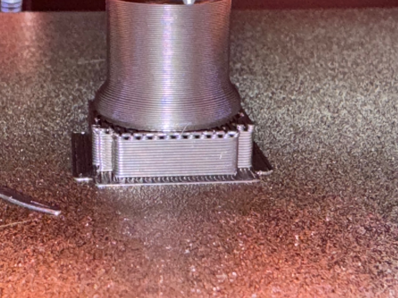
@Michael_Melancon What would you say the worst case amplitude of the waves were? You could potentially try to measure that with a straight edge across it and poking strands of copper wire down into the valleys or something?
Well, hopefully that’s a good dose of perspective and peace of mind. That’s a good looking part.
Very small. In this worse case you can see it from across the room very easily and feel it easily.
Sometimes you can see it, but to feel it you have to rub your fingernail across it to feel the vibration.
Sometimes you can’t feel it, but you can see it.
And sometimes you can only see it if you look at it in the light at a certain angle….
![]()
Yeah, that’s kinda the issue. It’s crazy how sensitive our eyes and sense of touch can be to that kind of thing.
I’m wondering if it’s not necessarily a lack of stiffness in the motion system, perhaps more that it’s the spring effect of the stepper motor holding torque combined with the inertia of rest of the motion system. That would explain why the amplitude might change with belt tension (more force on bearings, more static friction, higher damping coefficient) but period wouldn’t (assuming the belts are orders of magnitude stiffer than the stepper itself). A 0.1mm peak to peak amplitude with a 20T GT2 pulley would be roughly +/- 0.4 degrees. I wonder if that would be visible on the pulley itself.
I can’t reason my way to a conclusion about how that would change with different pulley sizes. Essentially the spring would be constant in an angular sense but with a different lever arm from the different pulley dimension. That would change the effective spring rate which should change the period, assuming no other changes. Changing the pulley size will also change the inertia of the system which would change the period and at that point I’m in the weeds enough that I don’t have a good gut feeling on the magnitudes of the effects at play here.
I’m trying to figure out if that would be testable by raising/lowering the stepper current. My gut feel is that more stepper current will lead to higher flux density or ‘holding torque’ which would lead to smaller deflection for a given applied torque, which should look like a higher rate spring, which would change the resonant frequency. That sounds plausible, to me?
So perhaps trying with a dramatically different stepper current, either higher or lower?
Not super confident on that one, I think it would only be likely if the ripples are extremely shallow. If they were step sized then the stepper would ultimately skip to a new step, so I’d say anything less than a step would be possible, well below a step would be plausible.
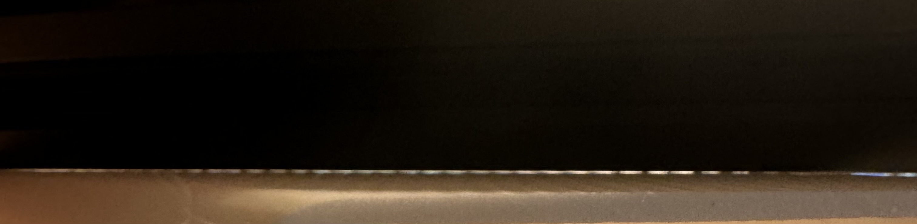
It’s tough to tell from the bloom but if that pitch is 3mm, that could be 1-5% of the pitch? So 0.03mm to 0.15mm? If you took a hair and put it in one of the grooves, would that straight edge pinch it? Most stranded hookup wire in the 26-20AWG range is 0.16mm. The 24AWG wire I have here is 11 strands of 0.16mm. Do you think a single strand of hookup wire would get pinched in the gap shown?
I don’t know if it would help you, but I ended up using 1/8" mono plugs for the MPCNC. Made it easy to eliminate the pin pushing back problems I chased for a month on the DuPont pins and to switch when they went the wrong direction. Two plugs per stepper.