Just to clarify, EstlCAM has two “functions” - CAM and CNC. The former is what you want to use. The latter is a controller firmware that is hardware specific to the EstlCAM controller (not what you have).
The two functions have different icons in the Windows start menu, but it is possible to enter the CNC function from the CAM setup menu (Setup - CNC Controller), which can cause some confusion. Ignore that setup menu option, it is not needed for your controller. You will need to configure Setup - Basic settings and Settings - CNC programs / “post-processor” menu options
As soon as I try to run the crown file it pops up the window with the aforementioned controller screen shot. Not sure how or where am I going wrong and I seem to be getting more confused by the minute lol
Sorry but I need a lil more clarification. The limit switches make total sense to me as a hard stop for setting zero/home but if I don’t need to set any limits for the work area how does it know the size of my table and where to stop since there are no limit switch’s at the far ends of the Y or X axis. I assume Z down limit is set by the probe and up is set by the limit switches.
Is there a for dummies step by step walkthrough.
Wifi connection wise I seem to loose connectivity a bit and my PC is less than 8’ away the LR4 guts are wide open still, so no wire issues. Could be wifi interference I do have powerful APs all over the place here. I have changed wifi channels of the JP3, well see if that resolves it.
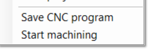
After you save your .gocde file, you then put that on the SD card and put that in the jackpot. Then from the webui you can run the file. We cant run the file direct from Estlcam.
We handle this by not setting up a job that is larger than our work area. IF the machine goes beyond its limit the worst that happens is some grinding noises from the motors. It sounds bad but doesn’t hurt anything. Just need to make sure you home the machine again after that happens.
Oph that clears that up lol. So there is NO way to upload a cut file directly through Estlcam or the webUI to the JP3 then. I just assumed it was all baked in drag n drop ish.
Ok so what about the squaring process I am still confused about that
you can connect to the webui from your computer and put the gcode file on over wifi. But you will have to save it out of estlcam first. You cant do it directly inside of estlcam.
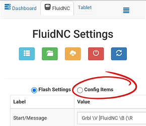
Auto Square on this board is as easy as editing each endstop individually directly from the “Config” section of the WebUI (or directly to the yaml file).
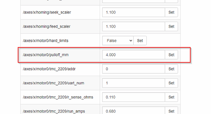
From there you have a “pulloff_mm” setting for each endstop. This setting is how far the machine backs away from the endstop after it triggers it. This needs to be far enough to reset the trigger at a minimum and if your values should be within 3mm of each other. If they are not it is best to move the endstop triggers.
Be sure to save your edits at the bottom of the config screen, and then by also using the red save button (macro) on the home screen!
Do you have a v bit? Best way to do it is put down 4 pieces of blue painters tape (or whatever tape) and manually drive your machine to the farthest 4 corners of the table. Go down in Z on each corner just until the bit touches and leaves a tiny mark. Then measure diagonal to see how in or out of square it is. From there we can help you make the pull off adjustments.
For Z you home Z and move down and probe with the touch plate (if you have one) on each side X Min and X Max. Then see which side is moving farther than the other, take the difference and add that to the pull off on the size that moved farther. For this one probe a few times and take the average. Do your best to not move the touch plate at all.
I am sure someone else can explain this way better than I can. But I did my best
You are doing great explaining thank you for your patience and I believe I understand you clearly.
This is where I was confused as to how we obtain the number data to set which I referred to as the table limit (we don’t care about the table limits only that its squared up)
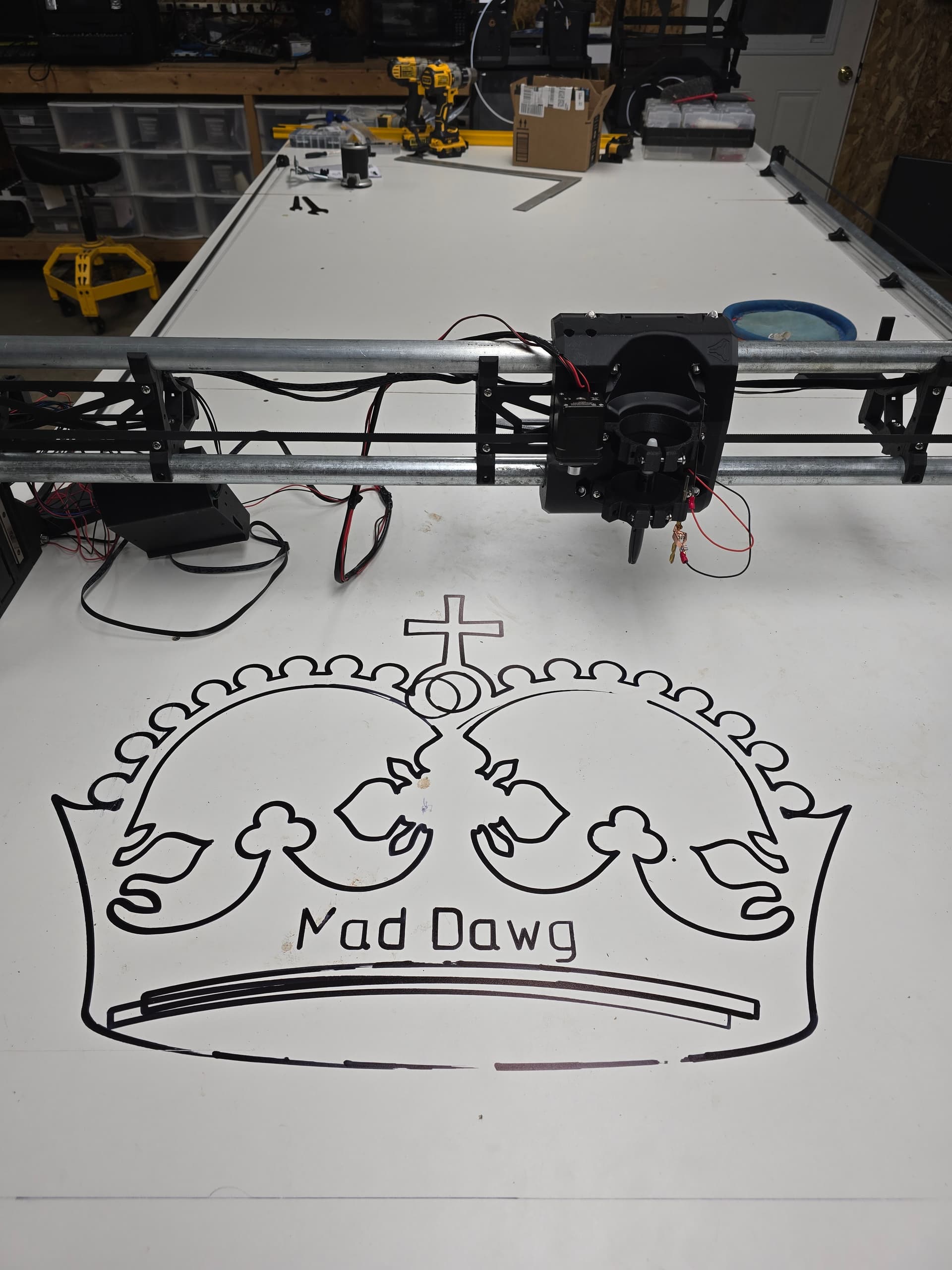
I don’t have any bits or even the makita 701 yet its all ordered just haven’t arrived. I was going use a marker with the makita mount I 3d printed.
Since there is no Z probe working I guess I am hosed until the router gets here unless there is a way to visually/ manually set it.
You can use a pen. That will get you close. Fine point and barely touch so it doesn’t skew. Once you get your router and some bits you can run it again to get it even closer if you want.
Thanks Jonathan gotta get a spoiler board going the marker showed that my table has some humps lol. Then the strut plates and followed by a table. I truely appreciate your and others assistance
Well I tried to cut strut plates today from the generator but I found that the screw holes were too big for the screw heads. I checked in estlcam and it shows the holes as 5.3mm.
I suppose I could use washers but I’d rather get it right). So I bought the Estlcam software thinking it may unlock features like multi select but honestly so far I haven’t noticed anything different from the free one.
Anyways shocker I have more questions lol.
Is there a way to select multiple items in estlcam i.e. resize all the holes at once. holding shift is a no go.
Does anyone have details on wiring the JP3 with a relay to start the router in software.
Not sure if this is a taboo question and if so I do apologize in advance but I have seen some references regarding moding the RTC701C to allow FluidNc to also software control router speed (like a spindle)
Tips for others building
Using this command “$X” in the Fluid terminal will save you a lot of plugging and unplugging of the power cord while your figuring things out.
I also switched my wifi to connect to my network as a STN and assigned it a static IP.
This has resolved any disconnects that I was getting and as a bonus I can reach the FluidNC gui from any chrome device on my network which is very kewl.
I use ESTLcam v11 and there are features for auto-creation of hole cuts and part cuts, etc, and I’m sure that’s a feature in v12 too.
Also, there is “marquis select” (draw a rectangle around all the cuts).
If you used ESTLcam to output your cam file (Gcode), look at your project in ESTLcam and make sure they were hole cuts inside the holes instead of part cuts outside the holes. If your tool is about the same size as the holes, then ESTLcam will usually balk and not put a hole cut it thinks the tool is too big for. In such cases you can mark it as drill operation instead of a hole. You can also fudge it by reducing the tool diameter ever so slightly until ESTLcan calculates the tool can fit in that hole. The amount by which you fudge that becomes the amount by which the actual holes will be slightly too large.
Thank You Again Doug I suspect you nailed it with ”part cuts outside the holes” zooming in and moving around objects or trying to re-center the view in Estlcam seems a bit flakey to me but its likely just me not knowing how to use it