Thanks Phillip
1 Like
I added some information. ![]()
![]()
Hello All
Quick update
The new linear rails I ordered actually came with extra ball bearings. A small magnetized screw driver allowed me to replace the lost ones (yeah)
Hopefully getting some MDF and conduit today to create a temporary table and get her fired up.
So I think I am in the home stretch now, but its possibly the harder part. wiring in the controller.
That said I ordered the jackpot 3 board and case from V1 but my board does not look like the one in the instructions (not a surprise I know its the newest option).
However my case does not seem to orient the board very well. (i.e. the sd card slot and RJ 11 port are not accessible as the existing case openings do not line up no matter how I place the board.
Two questions
Do I just make my own holes or is there a different print file for a newer style board case? Even if I did make my own holes i would need to use a pair of needle nose to be able to change the SD card.
I assume the board itself is pre flashed so the SD card is really only needed for loading files. I will only be accessing it from my internal network PC, so maybe its not even really needed in my use case.
Thank You in Advance
MD
1 Like
Did you use the Jackpot V3 case?
Firmware loading is done over USB, but you won’t need to do that generally as Ryan ships them pre-loaded.
The SD card is where you put the gcode files you want to run on the machine.
If you want to run a sender on your PC, then it’s a different discussion (and it’s not advised, normally we put files on the SD card and then use the Web UI to start and run those from SD)
1 Like
Thanks Jim
I bought the case from V1 but it looks like it shipped with an old model
thank you for the link that one looks more like it. Printing a new one.
OK, paging @vicious1 on that one. Glad you’re able to print up a replacement.
Sorry, I was pretty sure I shipped one or two on the first day of release with the wrong case. Sorry about that. It was such a hectic day and so many boards went out, the next morning I was packing up a printed parts set thinking…“I know I have not started printing v3 boxes how did I send those out yesterday…” Duh
Let me know your order number and I will take care of it.
2 Likes
No Worries all good… damn canuks eh! lol, ![]() gives me an excuse to use my new H2D.
gives me an excuse to use my new H2D.
I have discovered something else though, the kit I purchased was for 32mm my thinking was that thicker gantry = stronger anyways. Up here in winter wonderland our 1” EMT conduit is 29.8mm OD. So no problem with that however 32mm doesn’t seem to be a standard stock item at our local building suppliers.
Went and bought 1-1/4” EMT thinking that would be the right size but its actually 38.8mm OD. No bueno so If any other canuks have a source for a premium 32mm OD option I would sure like to know. I may be not calling it by the correct name but I am also in a pretty rural area. Anyways I know there are no print files for 38mm so I will just reprint for 29mm and I should be ready to assemble and test fire.
Ryan I am thoroughly enjoying your build and I am in no way complaining about any part of this experience. Im loving it, i am just lucky I got the 3d printer and am learning quickly how I can use it for these types of projects.
Since I basically now have everything to build another one I’m thinking about making 4x8 laser cutter or something else dunno yet but either way this is all a win for me.
Thank you all for your assistance
2 Likes
Another good use for your H2D might be printing the braces and Y rail clips for 29.5mm EMT ![]()
Kind of a big country, so generically, Metal Supermarkets.
Edit: I see you are in Ontario. Also a big province… and wildly varying definitions of rural.
Thank you Daryl never heard of them before but looks like a great resource. I am also interested in various sized 8020 type aluminum extrusions do you have an ontario distributor for that as well. Thanks much
I’ve been happy with Faztek (https://www.fazstore.ca/) out of Montreal. Lengths of 94" or under ship without UPS freight charges. They package stuff very well. Cut lengths are cut square.
I believe that @macboy used them for his last machine, and was happy with them too.
Excellent thank you again i forsee a large table for my lr4 in the future ![]()
2 Likes
Ok so I am now ,squared, wired and fired
Web login -check
Movement check good on all axis
I’m stuck on Limit Switch connections to a jackpot3.
Does any one have a pin out or wiring diag. for the the jackpot3
I cant seem to locate one, I would also like to know what the other connectors could be used for.
Thanks in Advance…im getting close ![]()
Have you looked here?
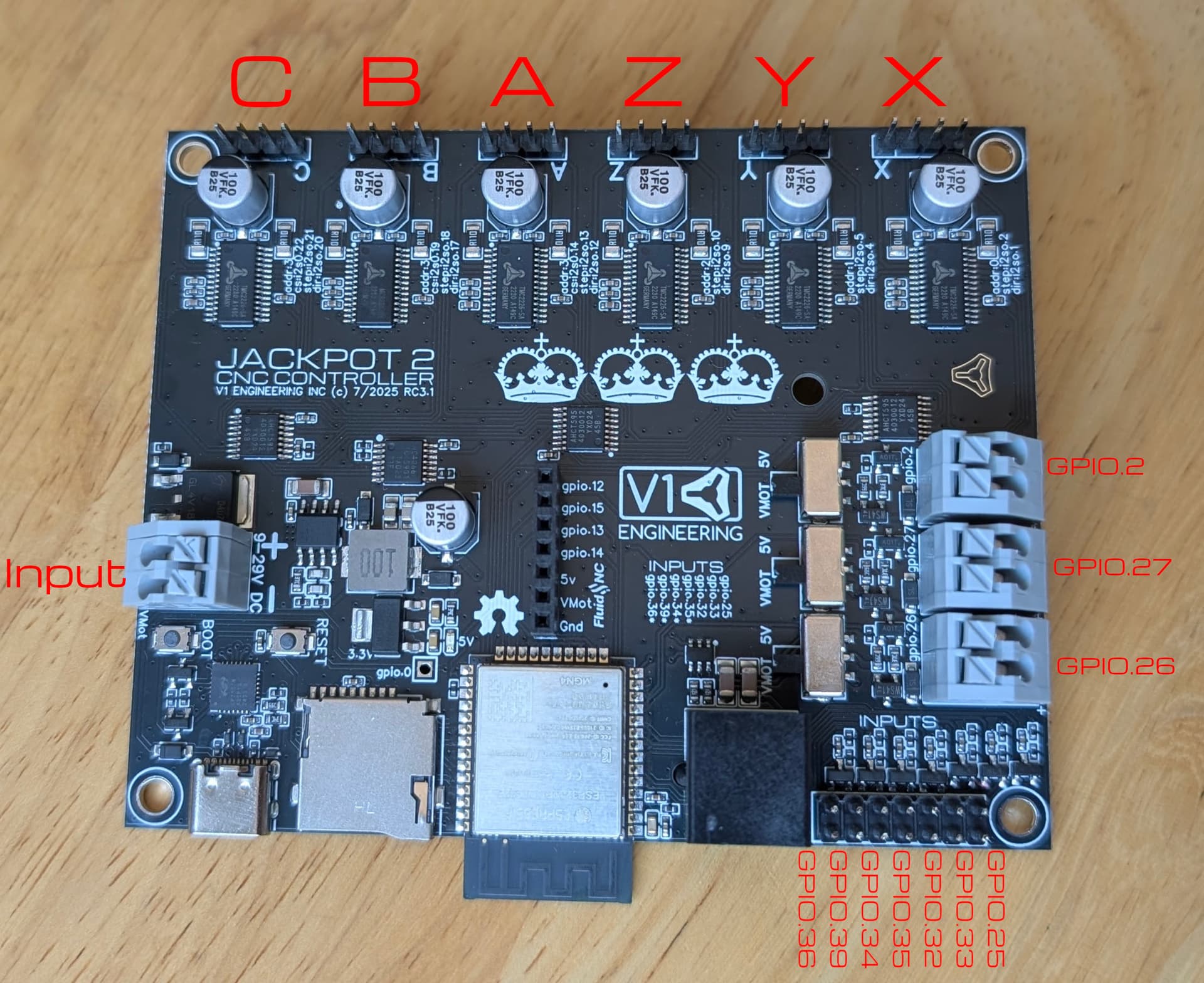
Admittedly, Ryan should have labeled with the same CBAZYX on the endstops instead of the GPIO numbers to make it easier. It should be the same as the jackpot 1. Same right to left, then skip one and then probe.
X - GPIO25
Y - GPIO33
Z - GPIO32
Y1 - GPIO35
Z1 - GPIO34
PROBE - GPIO36
Just to be sure I did verify this with the JP3 config and it is correct
2 Likes
Thank You much that was the key piece I was missing
I saw the image but I had no axis for reference to match the gpio # ![]()
2 Likes
No Problem
Yeah hopefully @vicious1 will see this and make an edit to the docs.
Yeah I need to finish up the jp3 section of the docs. I have a list of pics that need to be changed.
3 Likes
Build Update and clarification questions
LR4 is built and running Big Thank You to all for your support thus far ![]()
I believe I am in the home stretch now anyways
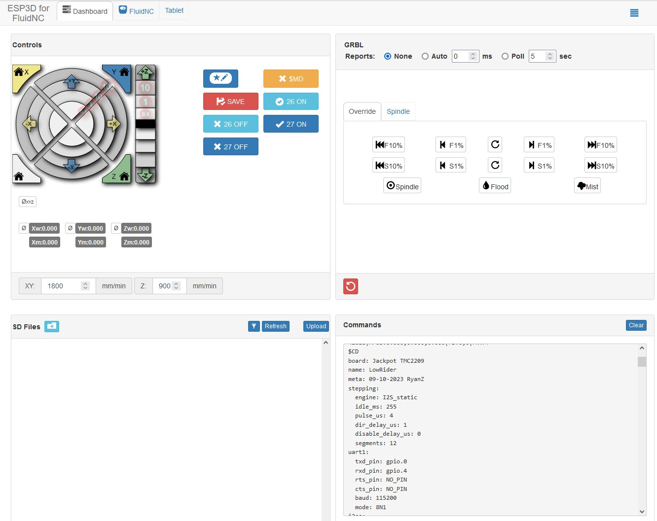
FluidNC settings are as per the below instructions (Note: My WebGUI on my new jackport3 does not show a controls icon upper left like this document image does) but everything else appears to be the same . My JP3 came with WebUi v 3.0.0.6 does it need updating if so. How?
Estlcam is installed and configured as per the instructions here
Crown DXF is loaded and ready to test using example pen settings.
What is unclear to me is;
How and where to set the limits of the work area. I see a reference to Auto Square in the FluidNC documentation but little details. I Looked at a few videos for a squaring process which seems to be straight forward enough but I cant find any info on how or where to actually set the hard limits of the work area ideally with a lil safety buffer. I assume this is a necessary first step to the squaring process. I must be missing some details with this bit.
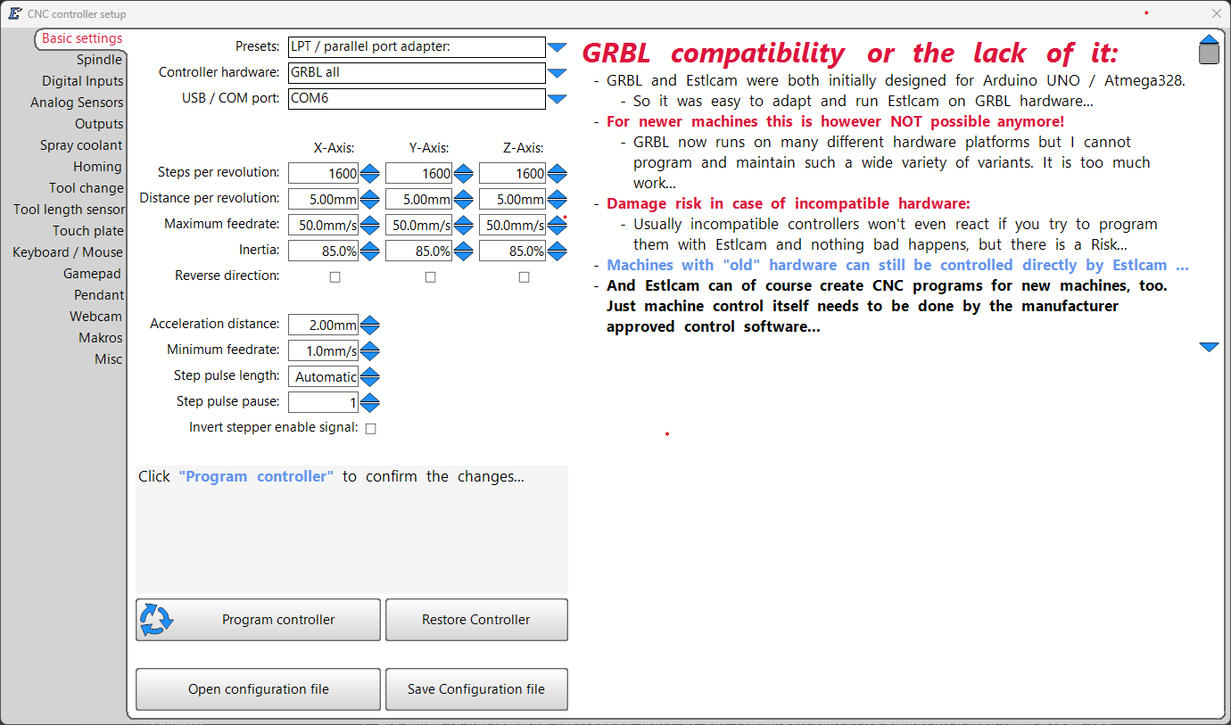
- When I try to run the crown file it wants me to input controller info. (screen shot attached Not sure what all to put here) I am connecting wirelessly to the JP3 from my Desktop PC which is also connected to the internet via ethernet.
- The wifi connectivity range of the JP3 is extremely limited and this is not a fault of the board design per say it is simply due to low power with a microscopic antenna. Given that my business for the last 20yrs has been as a wireless internet provider (WISP). I couldn’t help but notice that the power adapter already supplies 24v so it would be pretty easy to add a much more powerful wireless setup to this. Is there some sort of ethernet HAT or addon board that can be used to provide Gbit ethernet connectivity to the JP3.
Other than these few things I am really close and I have to say I am very impressed with the overall build and experience in this community. Thank You to All.
Best Regards
MD