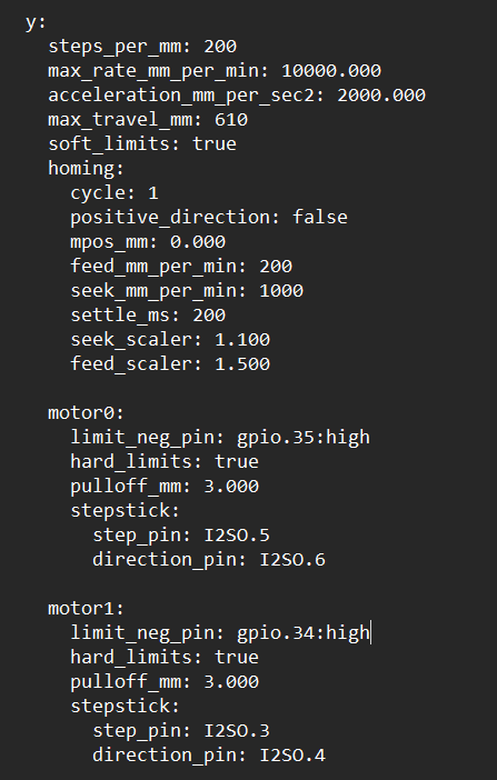
I am trying to setup autosquaring on a custom laser engraver I have made. I am able to get Y axis to home, but only if each side homes at the same time (already square). If the machine is not square, once one limit switch is triggered, both steppers stop. It should let the other motor that hasn’t triggered it’s endstop keep going until it triggers seperately. Here is my Y config. What do I have wrong here?
If you check end stop behavior with $Limits , are all end stops correctly paired with their motors?
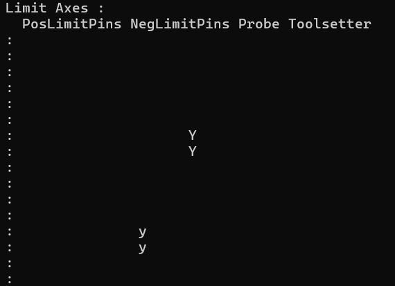
I believe so. When I trigger the left motor, the lower case “y” is triggered. When I trigger the right motor, the upper case “Y” is triggered.
Even if they were reversed, why would they both stop? Wouldn’t the wrong motor just continue to move?
What does the terminal report when you do this?
There’s two scenarios.
- When the left side stepper engages its endstop first, then both motors stop and eventually get an error stating that homing approach failed.
- When the right side stepper engages its endstop first, then both motors continue to move until the left side finally engages. You can actually here the right side motor crashing into the endstop as it’s waiting for the left side to engage.
It’s like everything depends on the left side, or Y1.
Videos of both scenarios below.
Not sure if these videos work. Not sure how to make it work with Dropbox.
$limits, that Y should move it should not be in the same position. If you are unsure try to get a screenshot of both of them.
Yes, the two are in different columns in the $limits reporting.
Are you sure you have them plugged into the right ports, both wired individually?
I am not seeing how this can even happen unless they are wires in series or something.
maybe show us the rest of your config.
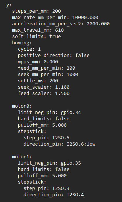
Nailed it. I had Y2 plugged into the Y2 slot on the DLC32 board. Which is just an extra slot in series with Y1. I switched it to the Z slot and I am getting closer…
Now when I home it, both motors approach Y=0 as they should and I can tap the Y2 limit switch over and over again to make the motor stop and start and become unsquare. That is good. But when I try that with the Y1 limit switch, it just stops both motors and wants to finish the homing sequence.
Does that make sense?
Here is my config.yaml right now.
Here is confirmation of seperate limit switch inputs.
Sorry I assumed you were using a jackpot.
Do you have a wiring diagram for that board you can share? My configs are not going to work out of the box, I have a feeling there will be a lot of edits.
There will indeed be a lot of edits.
The DLC32 has a very sparse documentation page in the FluidNC docs:
Edit- only the DLC32MAX is an ESP-32S3. Let’s be sure which flavor of DLC32 is in use.
The “Factory” DLC32 firmware has previously been a private fork of FluidNC.
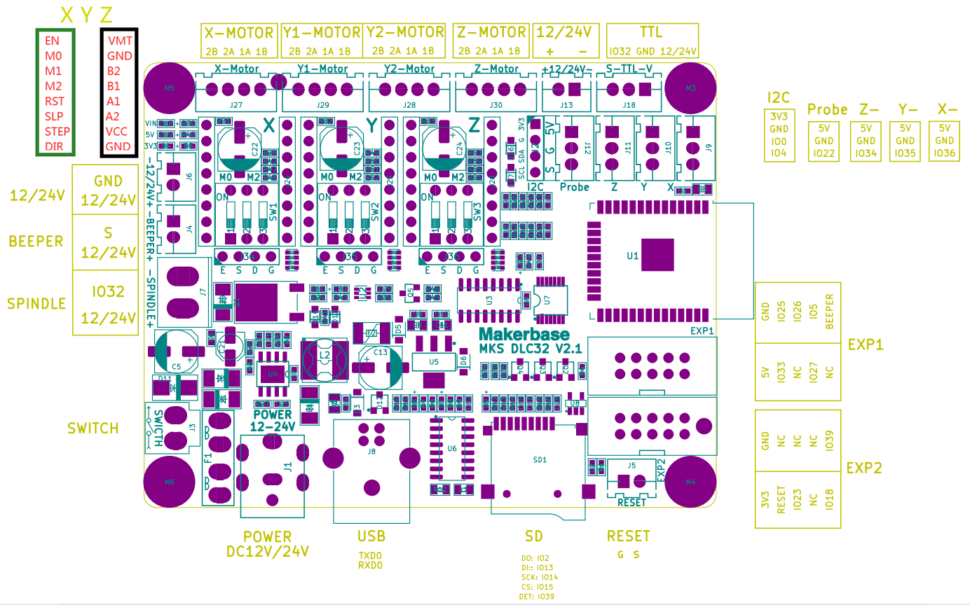
Here is a pinout for it. It is not a DLC32MAX. It is just a DLC32 with an ESP-32.
It has been a while since I started the project. I don’t believe the config originated from any V1 configs. I believe I derived my config from a basic dual axis config I found in FluidNC github or something somewhere and I have adapted it to my machine. Everything works great. Laser controls, movements, fan controls, etc.. Just need to finish the dual axis issue.
I bet the y1 and y2 are not separate signals. Have you ever driven them independently?
For the UART you can have up to 3 drivers on it. If they have 4 they would have 6.
Yes that’s what I was saying here:
I was running my Y motors on Y1 and Y2, as they are labeled on the board. Then I realized that the Y2 slot on the board is actually just in series with Y1 on the board (shared TMC2209). So I left Y1 where it was and then moved Y2 over to Z (as I have no Z anyway on my laser). Now I am getting closer to my end goal, but I am now having the issue described here:
1 Like

The board was made for a 4-stepper CNC, that’s why you have 2Y and a single one for X and Z. You’re not going to be able to configure autosquaring for the Primo, which needs 4 separate ports for it
I am not using this on a Primo. It is for a custom laser engraver with no Z motor. Therefore, I reassigned the Z to Y2, allowing me to autosquare the Y.
1 Like