There is a chain link button that also gets the number. But quoting or making a link is more useful than a number.
The firmware is pretty simple and it isn’t magic. Something simple is causing the issue. Sorry if we keep repeating the same things. It usually works and I restated it more clearly to make sure we weren’t miscommunicating. MakerJim’s ideas are the next step. He’s on a good track here.
I wasn’t clear. Yes the link is there in the quote or the slider at the right. But it isn’t displayed in-frame on the individual post.
That means that you have to either scroll around until the post number on the right matches the one you’re referring to, or otherwise infer it. If each post had, on the post itself, a post number, then the functionality would be much more useful.
Yeah, for long and complex threads we need to quote to keep context.
Yes this has to be simple, but not obvious yet.
Because there’s been so many changes, I strongly suggest @Just_bright goes back and methodically checks the Z endstop switches with the M119 command.
@Just_bright - Yes, I know that you’ve said that you’ve done this already, and yes, I know that you’ve said that they’re working properly, but please, let’s double (triple) check to make sure that there’s no misunderstanding or miscommunications.
Start by doing an M119 command with no switches activated (position the gantry and core in the middle of the table). Take a picture.
Then activate and hold one Z switch (use tape to hold it) and take another picture.
Then release that switch, activate and hold the other Z switch, and take another picture.
Do the same for the single X switch, and for both Y switches (one at a time).
My guess is that the switches are working, but are connected to the wrong terminal at the controller (z2 possibly swapped with one of the Y switches). But we won’t be able to pinpoint the problem unless you retest and show us pictures of each step of the troubleshooting process.
Note for the above, you may need to do an M119 command for each step.
Also when you post the pictures, please include some text to describe which switch you’re activating for each photo.
Thx
Well the video in Post #209 clearly shows you going to the Movement menu, selecting 100mm/move, then (after moving Y twice) pressing the Z+ button to move the gantry way past the endstop switches (with predictable results).
This is what I was referring to in my post # 234:
Please understand and accept that some of your statements (for example that you never use the Move command, that you only ever use the Home command) are in conflict with other posts that show you doing exactly the opposite.
I get it that you are frustrated. But please,
- Take a few deep breaths.
- Accept that you may have been mistaken in some of your assumptions.
- Let us walk you through the troubleshooting step by step.
- Don’t think that just because you have done something previously, that you did it correctly. There is a reason we are asking you to revisit these steps
- Don’t rush ahead or jump around trying things that pop into your head. Let us walk you through the process methodically.
If you be patient with us, we’ll be patient with you.
Ill do it again for you… but if u scroll up, u will see i did it methodically for Jim. …but I digress… on it.
One thing is though, isnt it obvious the right endstops are connected? When it clicks, that side motor drops. Maybe that happens if any endstop clicks…in that case ya u could be right i guess.
Back to the garage…
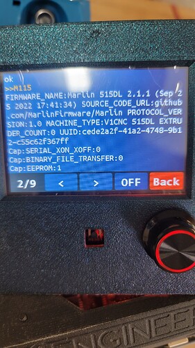
M119
You typed M115
No.
I’m going to start trying to explain things as we try and help you.
Part of the problem here, I think, is that you think you understand what’s happening but you acctually don’t.
So something “obvious” is only obvious if your wrong understanding is correct.
You’re conflating cause and effect. That’s not correct in this case.
When you are homing Z, it is actually two independent control activities. The left side Z is homing (UP), expecting to see it’s endstop trigger, then it will command that side to back off and more slowly go back up to re-trigger.
The right side is independently doing the same thing. It’s trying to move up to trigger the endstop, back away, and then slowly re-trigger.
When you seee the right side do that correctly, then drop- it isn’t the right side that has a problem. It just so happens that the controller has figured out there’s a problem about the time that happens.
The left side never stopped, never found the endstop, so the controller gives up, throws an error, and disables the steppers. Then the axis drops.
We’re trying to do a phasing check, and to do that we need to start over.
We start over becase every post or two multiple things got changed. Partly because you’re working with a bad understanding and thus potentially making things worse not better.
One step at a time, and we’ll get this.
Edit- and that’s the only way we can help you get through it. One step at a time, no other changes in between and we iterate on it. If we test, we’re verifying some things and if other things get changed then it throws off our mental model of the setup and won’t help.
Ya i noticed that. It does the same thing if u hit m119 at startup
I put everything back to “oem” configuration. The firmware is flashed new also and I havent done anything inside the settings. I noticed when doing the m119 commands per endstop that I was now getting an intermittent trigger on z2 or y2.
Im guessing that something got pinched when bundleing the harness.
So I am taking it all apart and rewiring everything today.
As for the phase check… I use the multimeter to check each of the endstop positions. Thats why I felt so strong they are in the correct spots.
Heres a question… I have the secondary motors and endstops on the rail side. So that is the side I call z2 or y2. That shouldnt matter though correct?
Ok, the reason that I was asking you to assert each endstop switch individually and take a picture was to ensure that Z1 endstop was associated with Z1 motor (and same for Z2, Y1, Y2, X). If you are 200% sure that the far (rail side) motor and end switch are both connected to Z2, (same for the Y2 motor and end switch), and the M119 commands show Z2 asserted when you close the rail side Z switch and Z1 shows asserted when you close the roller side Z switch. then I’ll believe you (although video or photo evidence would be reassuring).
If everything indeed is correct, the next thing to check is that both Z switches are actually being closed when the Z travel is at (or just before) the point where the lead screw nut hits the top of the YZ Plate. If the travel is htting the YZ plate but either of the limit switches aren’t closing, then that might cause the condition you have.
One way to check this is to MOVE (not home) Z axis 10mm at a time until it is about 10mm from the top, switch to 1mm at a time and raise the axis until it just touches the top of the YZ plate. Then do another M119 to verify that both switches are closed. You may need to adjust the limit switch holder down a bit, or you may need to carefully bend the switch arm.
And no, it doesn’t matter whether Z1 is on the rail side or the roller side, as long as both the motor and the switch are on the same side.
My bad brother. I saw the glitch on y2 and took it off to replace it because the metal tab was gone. Then i couldnt find my other endstops… etc etc. Just put this on the back burner again for … who knows. Almost bought a Langmuir out of frustration, but decided better.
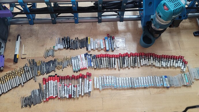
On a good note, the guy gave me about $800 or more worth of industrial endbits and whatnot from the distributors he never uses the small stuff haha.
Karma
Anyways…turns out the bits are all way too small for my use…
Edit-----Ryan
They do look okay though. What is “your use”?
Not pcb boards.
These are like .012-.03
Few 3mm (like 4)
Ah, okay. can’t see that with those in the plastic. The ones you can see look okay.
Good god! We sell all that at work! That is insane!
They just gave it to you? Fullerton is made here in Saginaw!


