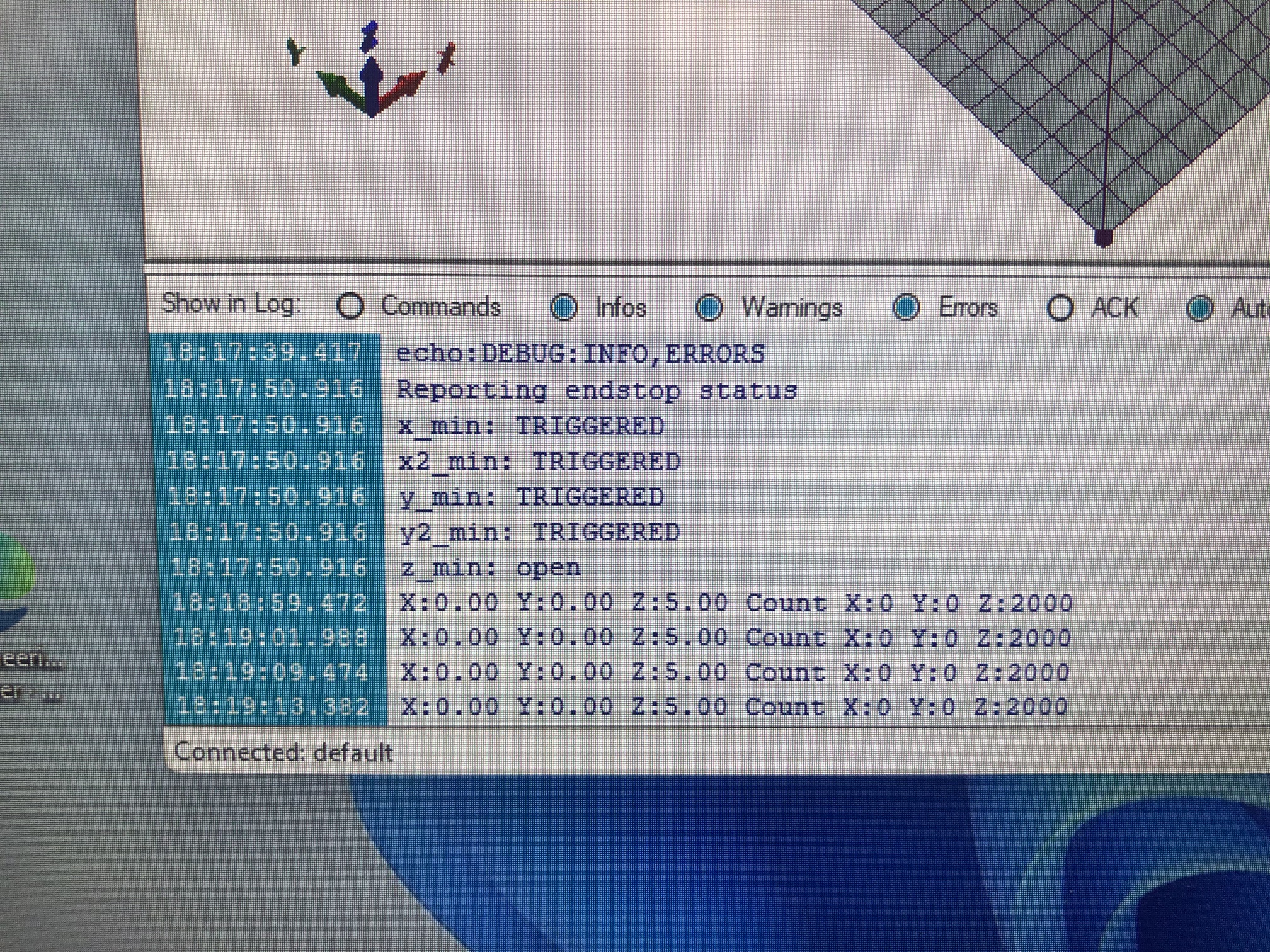
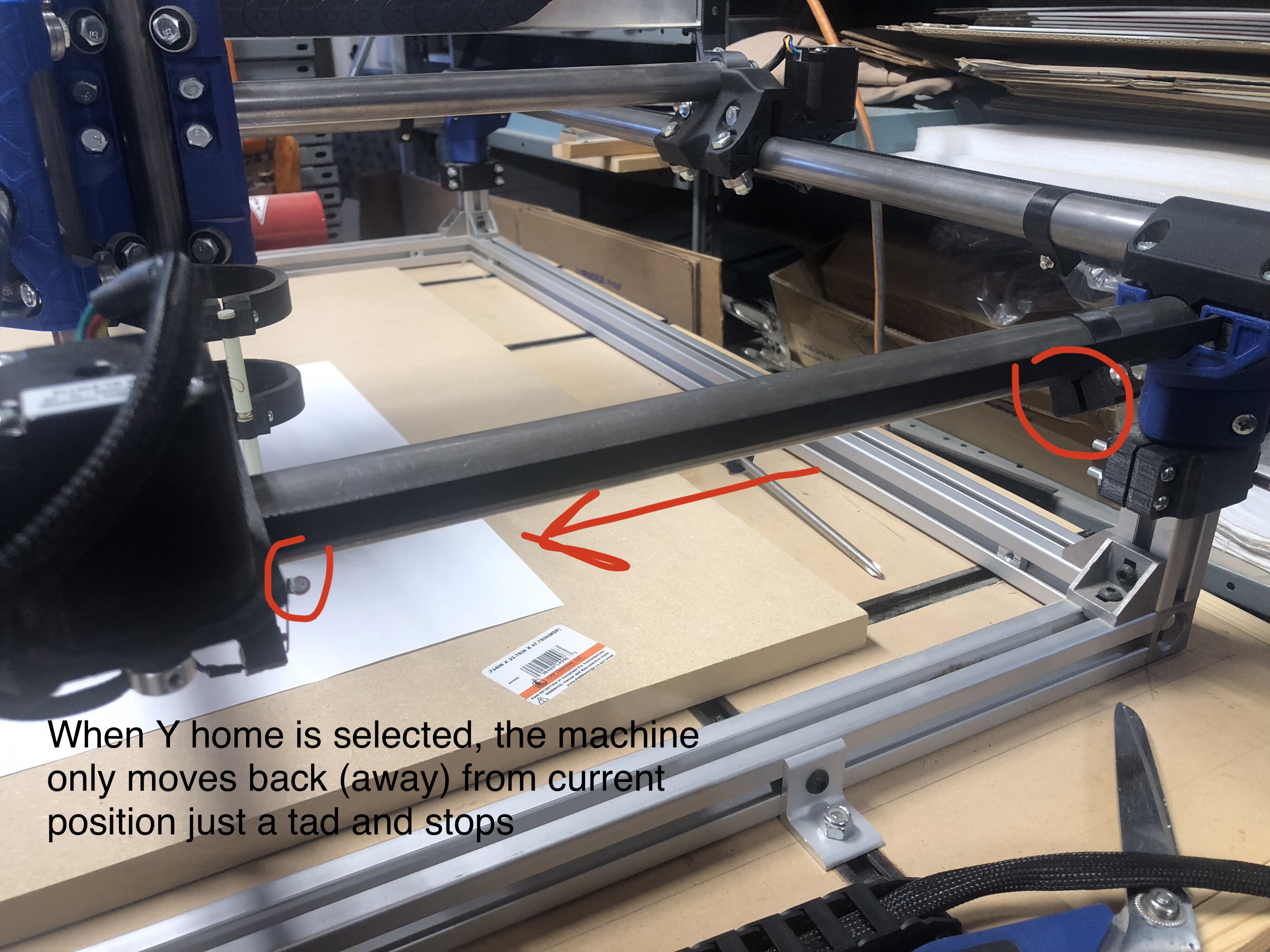
X axis will home just fine as does the Z (with plate). The Y axis when homing only moves back a tad as though it just hit the stop. M119 showed all ‘triggered’ .
I have the SKR Pro1.2 board with dual end stops. Same result with control board or using repetier software. Same results when homing just the Y or using auto home. Both Y motors back up just a tad as though both switches hit the stop even though they are nowhere near the stops.
This means that the circuit is at logic HIGH. This will happen if the switch is wired incorrectly (normally open jnstead kf normally closed) or if the wire ks disconnected somewhere.
Press the switches and try M119 again. If it now says “open” then your switches are incorrectly wired. If it still says “triggered,” then your switches may be incorrect another way, or they may have become disconnected, or you may have a broken wire.
Would that still hold true (wired incorrectly) if X works fine? When I select X Home, it homes to the stops then backs off a tad and then sets as it should. Same switches on all four spots… all wired same NC… If one switch has broken wire, would not the other still work ? When Y home is selected, both motors back up in unison as if both were hitting stops. Appreciate your help.
Did more testing… so when gantry is in the middle (i.e NOT against the stops) the M119 showed x1 open, x 2 open, y1 triggered and y2 triggered. Got me thinking. With my finger i pressed the one x stop switch and reran M119 and it showed x1 open, x2 triggered, y1 & y2 triggered.
I disconnect the wires from the board for each of the Y switches… ran M119 and it showed X1,X2 open, Y1 & Y2 triggered. Not even connected it should show open, would it not?
I did not run M119 with wires of X stops disconnected to see what that would show but i would assume it would show open. Might this be the board issue then and not the stop switches or wiring?
Not even connected it should show open, would it not?
No.
The term “open” does not mean an open connection. The V1 maintained Marlin firmware expects normally closed switches, so when the circuit is completed, you get “open” from the M119. When the circuit is not connected, you get “triggered.” The wording is not intuitive.
Since you’ve removed the wires from the switches, the next step to try is to short the wire for the Y1 and Y2 stepper and run the M119 again. If you get “open,” then you have a switch issue…either you’ve wired them wrong or there is an issue with the switch. On the other hand, if it still reads “triggered,” you have an issue with the wires, the wires’ connection to the control board, or possibly the control board itself.
There is a known issue with the endstop electronics on some SKR Pro boards, but I would eliminate other potential causes before going down the road of a replacement or a fix for the SKR Pro board. If it turns out to be a control board issue, you can either 1) replace the board, 2) remove the LEDs that are triggered by the endstops, or 3) add a pullup resistor to the signal pins.
Like Robert said, disconnected will show Triggered.
It works like this. “Open” is logic LOW, “triggered” is logic HIGH.
A resistor connects the switch pin to a 5V source, so when nothing else is connected, rhe voltage rises to +5V and it reads as logic HIGH. This is the state with the switch open, or disconnected, or a broken wire. (Also, the SKR Pro has LEDs that should light up in this state.)
The switch is connected to ground (0V) and the switch pin. A short circuit to ground drops the voltage to (near) 0V – or at least below 2.2V which the MCU reads as logic LOW, or open.
This is true, but it’s the opposite effect, where the switch reads as “open” even though the LED is on. It happens because the LED draws wnough current to prevent the switch from reading logic HIGH and switching the state to “triggered.” I think we can rule this problem out from the start.
Troubleshooting:
Test the board. A jumper cap between the signal and ground on the board should make M119 report “open”. The LED for that endstop should go out. Removing the jumper should make it report “triggered.” The LED should turn on.
Test the switch. A multimeter should report near 0 ohms across the “C” and “NC” terminals on the switch. These are typically pins 1 and 3 on the switch and should be where your wires connect. Any value greater rhan 10 ohms across this is a bad switch. Just to be sure, the resistance should change to infinite when the switch is pressed (assume disconnected from the SKR Pro.) It should also show near 0 between the “C” and “NO” pins (1 and 2) when pressed, and infinite when not pressed. Pins 2 and 3 (NO and NC) should always have infinite resistance between them.
If the switch is OK and the board is OK… it’s got to be your wires. Something is connected wrong, or disconnected. I would check that the wires are connected to G and S at the SKR Pro (and NOT to V) and that they are connected to C and NC at the switch. (Doesn’t matter which is which.)
A BIG thank you to ALL who helped me troubleshoot the issue. turns out that when I jumped the pins on the board, and sent the M119, it showed “open” and at least that meant the board was working properly. so, I had to admit it had to be in the wiring. so, while I was looking at the pins I removed from the board, the colors of the wires caught my eye… and then I looked at the color of the wires on the two Y limit switches… and then again at the connectors and began laughing out loud so much so that I startled my dog who was laying by my feet. Red and blue were connected to one Y switch while black and white were connected to the other Y switch… but the pin connectors did not reflect that… I had black and red on one pin connector and white and blue on the other… both clearly labeled as such - LOL
I switched the pins in the connectors so blue/red on one and black/white on other and wouldn’t you know it, the Y axis homed perfectly. LMAO I know I never would have found the issue without all y’alls input. thank you again.