This might already have been mentioned but a standard independent z axis homing system to get repeatable leveling across X. I know you can use the dual end stops and people have designed their own z max or min systems. But something built into the standard design like the primo has.
Either that or a independent z axis like the primo but that might be blasphemy as it would no longer low ride
The grub screws on the 611 plate stepper motor seem like they would be really hard to get at with the stepper still mounted to the plate… I thought about adding a hole in the plate to have access from the bottom while it was assembled but that would be fiddly at best.
Sure enough, I could have left a little hole for the allen key. I figured the chances of lining that all up would be tough, so removing the two M5’s was the backup…added to the list for the next one.
For making the gantry rigid I am planning to add a small piece of flat bar to the bottom of the tubes, something like 1/2" or so as a fin at 6 o’clock. Doesn’t sound like much but will likely take all of the sag out of the pipes and should easily run through the gaps in the existing brackets.
I’m this would add a bit of stiffness vertically, though I doubt it would increase lateral stiffness much.
How would you add the barstock to the tubes though? Welding will almost certainly result in tubes that are neither straight nor round…Brazing might work…I use silver solder fairly often, and that minimizes warpage, but I’ve never tried soldering anything remotely that long.
Tig weld, only needs a few small welds down the length, not enough heat to warp or bend. Will measure the clearance, but a small angle could fit as well. I have a lot of history working and designing machines using pipe and tubing, it is a very interesting material that doesn’t behave exactly like you think it should. I have seen several wanting to try heavier wall tube, this will actually sag more, it is a factor of cross sectional area, a thinner wall will resit bending more then a thicker or even solid rod. The thicker has advantages in capacity and tornisional load, but in deflection the thinner will perform better as long as the load is less then it’s breaking strength. Another option would be to add a threaded rod inside the tube attached to plates at each end, the rod is then threaded out to apply pressure to the plates from the inside putting a tension load on the pipe, we did this for some very large screw assemblies, 4’ diameter, 60’ long. Works well, pipe and tube does not like compression, tension though it does.
For the tube under under its own weight, a thicker tube would sag perhaps slightly more, with X percent more weight and slightly less than X percent more moment of inertia since the extra thickness is added to the inside.
But from the weight and sideways loads generated by the router, there is no way a thinner tube will deflect less than a thicker tube. A thinner tube is not better at resisting bending in that sense. If you want a stiffer machine for higher feedrates or harder materials, thicker tube has higher stiffness than thin tube, even if the sag is not less.
It would be cool if the router were mounted on a vertical surface rather than horizontal so we could take advantage of things like the carbide3d router mounts or what is on the shapeoko. This would allow more control over how much of the router and collet sticks out of the bottom plate without having to be a victim to the design of a router base that comes with the router. Pros and cons to both though.
A few things that require improving on the current LR2 Plastics.
nut access on the X/Z-Tube bolts ( the 4 little bolts that squeeze both the vertical and horizontal tubes is near impossible to gain access unless using needle nose pliers.
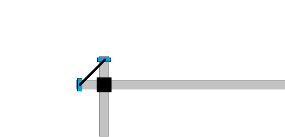
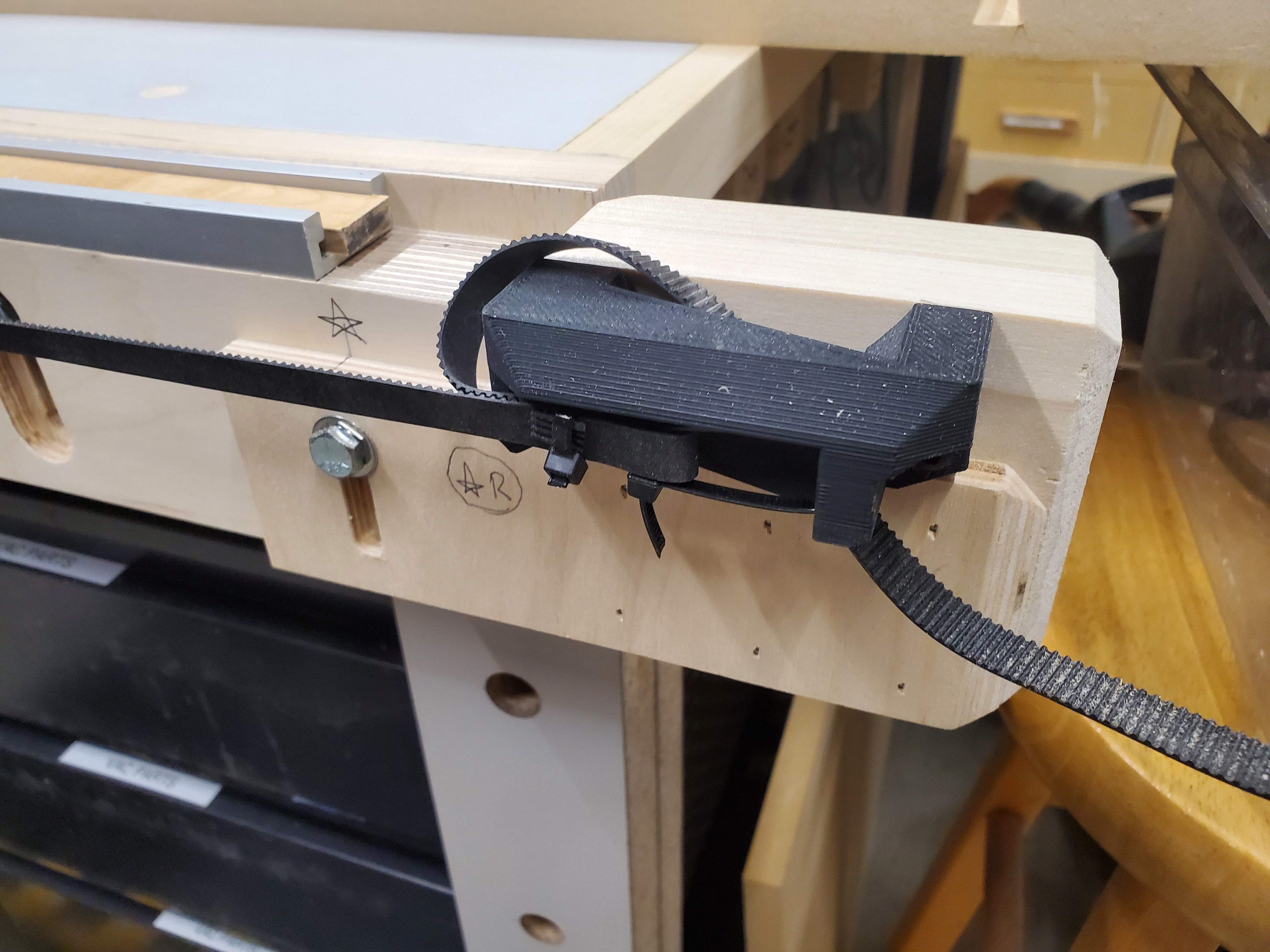
belt tensioning - zip ties are not the way forward. note - There’s a great belt tensioner on Thingverse (a Primo / LR2 hybrid) .
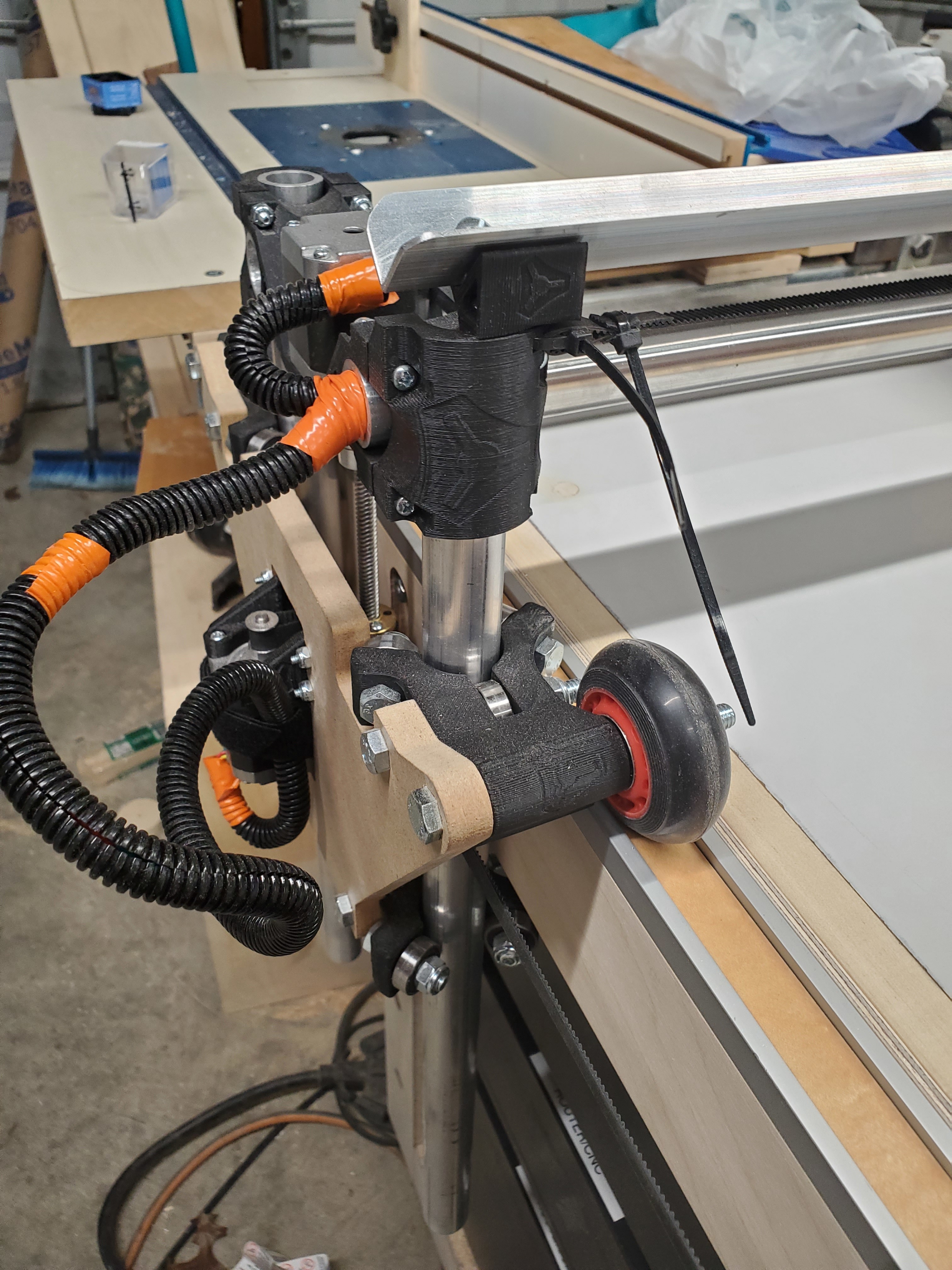
The Y plate should have ability to easily attach extra wheels beneath the table for added rigidity.
A Y-plate “wheel corrector” allows the operator to adjust slight variations in the angle of a wheels direction along the Y axis.
Now that I’ve used my lowrider some, I’d say the biggest improvement I’d make to it would be to have a fixed gantry with a sliding spindle mount for the short & Z axis. There seems to be a lot of room for alignment error with those 4 sliding tubes, and the added issue of it dropping when the steppers are unpowered are the biggest pain points for me. I guess with the current design you have a much larger total range for Z, but I think it’s rare to need more than 4-6" of clearance or 2" of Z travel for most stock.
I might modify mine in the future to be more like an openbuilds gantry for the short axis and Z, but lowrider wheels for the long axis.
I feel like this is the biggest advantage of the LowRider over any other large format CNC. The Z can be as tall as you need(within reason) and is the absolute most rigid at the depths of a cuts, exact opposite of what other machines are.
I totally agree with you, but this really depends on the distance of the gantry to the spoilboard. Of course, if you carve as low as possible the lever to tweak the Z pipes is also as short as possible and therefore it can take high cutting forces and be also quite accurate.
The higher the gantry must move because of a tall workpiece, the worse the ability to take the cutting forces becomes…
This is why I think the most improvement in a new Lowrider design would be more rigid XZ mains or even some additional braces. As you know, I made the parts out of aluminum tube, but to stay with the philosophy of mostly printed parts it could be an idea to make the tubes longer and brace them with diagonals.
A quick scetch may explain it a little better:
Yes and I think it is more that enough for the 2" max z that people use. Have you ever cut more than 2" up? 1/8" endmills are about 3/4" worth of cutting surface and most 4x8 (5x10) sheet goods are not thicker than 3/4". The LowRider is build strictly for sheet goods, the MPCNC is built for everything else.
The exception is people using the lowrider to surface large goods (or Ice) but they typically built them with a drop table.
Any thought to using phenolics? Rockler send to really like it for their router table inserts and other sheet good jigs. I wonder if using a 3/8 sorry, a 9mm-ish, thickness would do well?
Thanks for that! I’m reading this and thinking, “crap, I picked up a thicker tube vice thin wall to avoid the sagging” but I kept reading and there you were! My savior!!
I have not experienced a notable sag yet. I’m just cutting parts or so far. So just through and through. Once I get to some tray or stepped items I’ll check again.
Here’s what I have done to accomplish this. I created a removable block to hold the belt and adjust height of needed (though once it was completed I don’t think height adjustment will be needed) this mounts on the end of rails that also can raise or lower for my multi-purpose bench top where I can mill sheet goods with my circular saw. There’s a miter track on the top of the rails where the wheels of the y axis sit (too deep at first, but I placed a .25 inch strip in there and it’s good) I’ll use that miter for circular saw and router sleds for case work.