I had been thinking on how one might incorporate a circular saw, similar to what @jgunnar suggested, where you could manually move the gantry to do cuts. Cuts along the Y-axis seem simple enough, but along the X-axis I would think it would be difficult to keep the current gantry from ‘racking’ with the steppers turned off. I had a thought that incorporating 10-foot pieces of conduit running along the X-axes and attach a set of those three-bearing roller assemblies to the Y-plate might provide the needed stability. These conduits wouldn’t be supporting weight as they are just there to help the keep the gantry from racking. Therefore, their stiffness, or lack thereof over the distance, might not be an issue. I’m not sure if they will really experience a great deal of force… maybe that’s dependent upon how well you can manage to ‘pull’ the circular saw straight along the X-axis. As a side benefit, I would think they would also be a replacement for tracks that some of us have installed on our rails.
And since I’m planning on cutting new Y-plates and I have tons of skateboard bearings and bolts from a when I was working on incorporating a panel saw design into a maslow frame, maybe I can print something up to try it out… unless someone can tell my why it wouldn’t work.
What about adding a “toggle clamp” to the assembly that houses the bearings and bears on the rail so that any of them could be temporarily locked? Something with a rubber tip would prevent damage to the rail itself as long as it was appropriately adjusted.
If it were possible to dis-enable selected axis’ stepper motors (instead of all of them at once) you could achieve the same effect.
Mine dont flex either but when my brother cut them for me he screwed up and cut them out of 1/4" MDF so I epoxied them together to make 1/2" Y plates. Primed and painted them as well and they may not flex but I can never seem to get them perfectly squared.
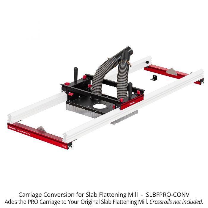
The gantry on this is one idea that looks like it could accommodate a swappable platform. Could see a default open base with different inserts for different tools, including a Router on a Z axis. Looks like it has locking knobs to fix it to the rail when needed which would be great for a panel saw-type operation. Guess they could be level adjusters but some locking concept could be added fairly easily.
In fact, that whole setup could probably be turned into a CNC rig in a number of different ways if you wanted to just pay up front for a certain degree of precision.
OMG! All this talk about circular saws has me envisioning gantries getting thrown through walls/doors or worse the operators. There is a very good reason panel saws are as expensive as they are. That is they cut straight every time and have a lot of safety features put into them so the boards or the saw don’t become a weapon,
I would think one of the biggest upgrades for the LR2 would be to ditch the cross rods and replace it with a vertical piece of MDF and attach 2x MGN12 rails on it. It would be super rigid and cost effective. You would create a pretty heavy gantry as you would also want the sides to come up and attach to the vertical to really create a strong rigid gantry.
There is no reason in my book to bother with adding trunnion tables rotary tables etc to make it 4+ axis. This is a sub $1k machine. With that comes people that probably have never used CAM software and thus never programed 4+ axis machines. You won’t be able to afford the CAM software to create the tool paths for a 4+ axis machine. If you can then why are you wanting to use it on a sub $1k machine? I’m sure a few people understand what I’m saying. Fusion360’s CAM is a Alpha program at best. IE. don’t expect it’s free version to be able to do CAM for long for 4+ axis work.
As far as the gantry moving because of a lack of a track has been something that has concerned me mainly for large jobs that will have the gantry move across the table say 30+ times. Without a track of some sort you can never expect it’s short axis to be where you expect it to be. A single rail on one side of the top of the table would seem like the easiest to implement idea. Staying with belts will keep costs down. I personally use steel core belts so I don’t have as much belt stretch, but would love to see a rack and pinion setup (not 3d printed). The extra cost would probably be around $300 I think off the top of my head so staying with belts just makes sense for cost effectiveness.
Really putting a belt tension solution similar to what the Primo has would make sense and you already have it figured out so it’s almost a no brainer.
Yeah I have been giving the LR a re-think. I am pretty sure we are on the same page with most of that. The weakest point is certainly the rails, I am sure I can come up with something else without breaking the bank. I am not ready to start sketching yet though.
Those will break if they have not already, guaranteed. The failure time is usually measured in hours of use in these builds. Kevlar or the lesser glass fiber lined belts are the right choice here.
I think most are talking rotary axsis and CAM software is relatively cheap 300 to 1500 and some free form true 4th axis with undercuts and such much more
Thank you. I’ve been wondering about that since there are some pretty major bends in the belt plus using a 16T pulley. I do have several hours on my Burley before I stored it away last year. I’ll have to get some Gates belts as they are my goto for Kevlar belts. IE. I know what I’m getting for my money.
BTW I think I came off cocky and that wasn’t my intent. I so often see people ask for 5 axis machines without them ever having programed or even ran a 5 axis machine. ie. it’s a small niche that can/will actually get use out of it. Most things done on a 5 axis can be done one a 3 axis machine and several setups. I see many people having issues figuring out fixating/work holding involving multiple setups and that is where most of machining boils down to. ie. Figuring out how to hold something or planning for it. Obviously a rotary 4th axis has it’s benefits and when people learn how to use it can be very beneficial for machining things that have features all over. And mounting a circular saw to a gantry just scares the living hell out of me. Maybe a jigsaw but at those speeds you would be better off just using a cutter.
Yes I have a 1off job i want a rotary for but sliced cutting will do and easier also. I like your thinking and didn’t take it as cocky everyone can has a opinion and a answer and is entitled to voice it. I love my 600$ dollar machine and it far exceeded my expectations and abilities
Genuinely curious: Assuming an axis could be fixed, how is using a saw guided by the unpowered free axis of a CNC any different than the operation of a track saw or a circular saw-based miter station? Isn’t just a straight reference?
I’ve been doing alot of work on the L2 lately, and with that comes making sure everything is tight. That being said, would a setup something like the attached photo be realistic (but using belts)?
With our current L2 setup, it would be riding on the side of the table and not on top, but I would think it would fair better and keep the tensioning…
I would think to keep tension, you’d only have to adjust the rollers that ride against the belt rather than at the ends of the belt. Although it would obviously only work for the X axis unless there’s an overhaul to the gantry.
I would think there would be a pretty limited range of motion for adjusting the motor, while you’ve got basically unlimited adjustability when setting up the ends of the belts, which need to be secured somehow in any case.
I was just throwing an idea out there to help keep belt tensions. With the setup I pictured, the only stretching or tensioning on the belt is between the belt rollers and the stepper. Rather than the entire belt.
But I guess the more I look at it, it would probably require a bit more rework than I was envisioning…
