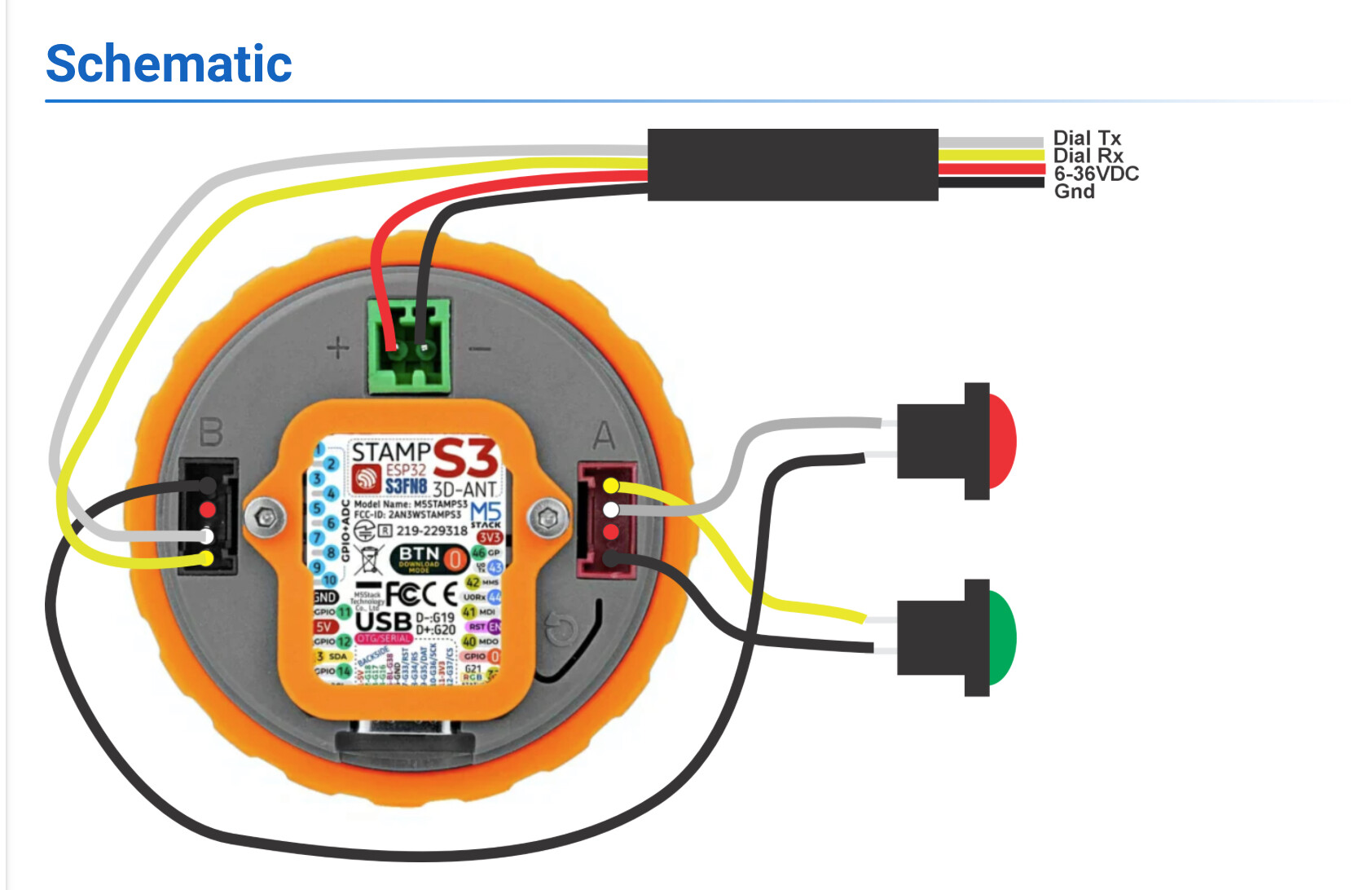
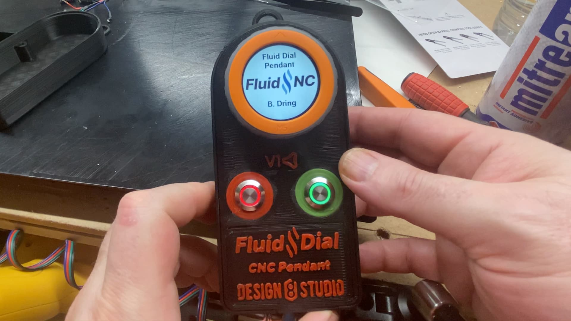
I’m wiring up three (3) things — two (2) 12v LEDs (inside switch buttons) and one 12v electronics device.
This is for what I’m working on over here:
I’m wiring up three (3) things — two (2) 12v LEDs (inside switch buttons) and one 12v electronics device.
This is for what I’m working on over here:
Thanks, but I have that schematic, yet it does not address my situation. Both my buttons have LEDs in them capable of accepting the same voltage as the dial, and I want them lit up.
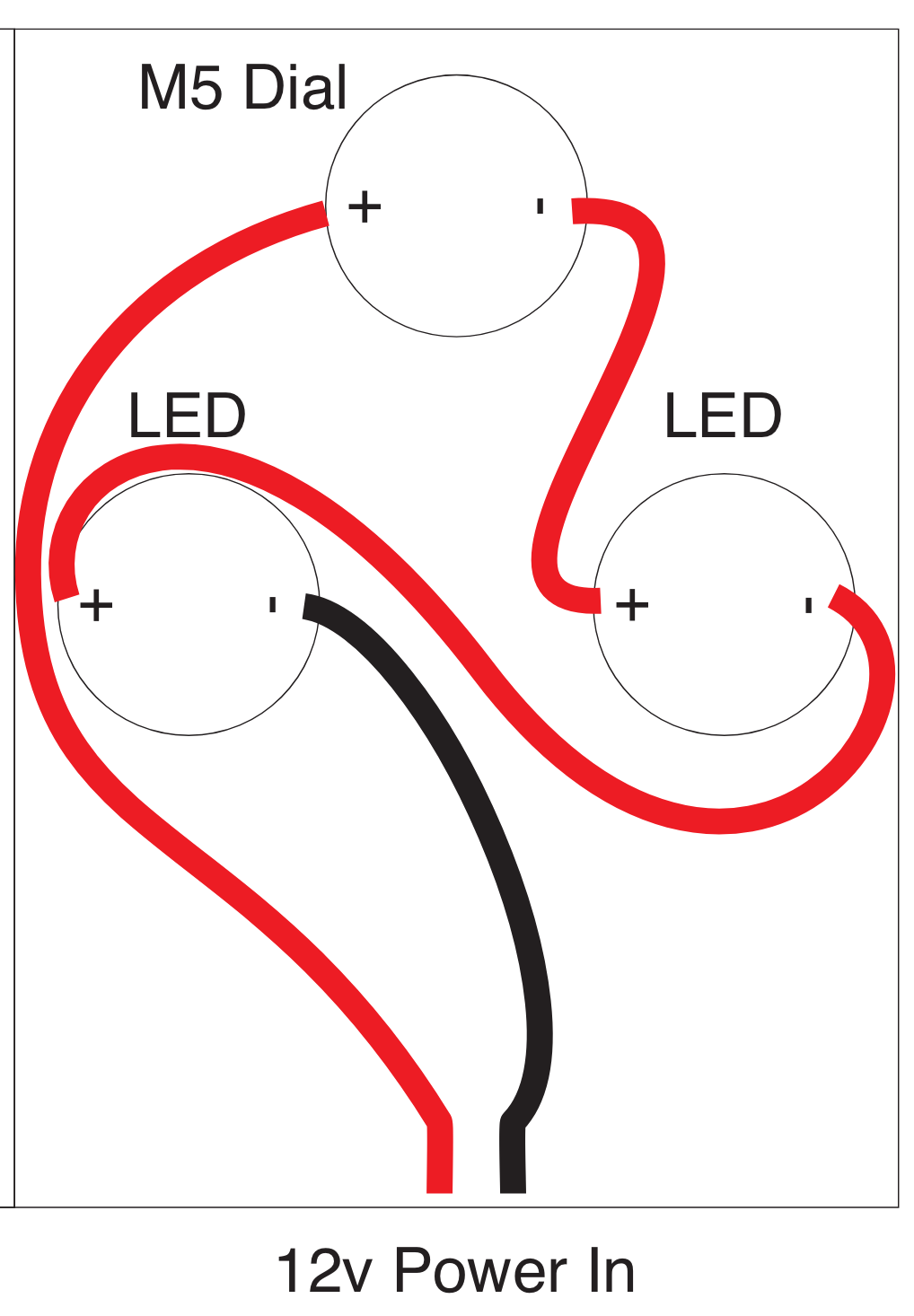
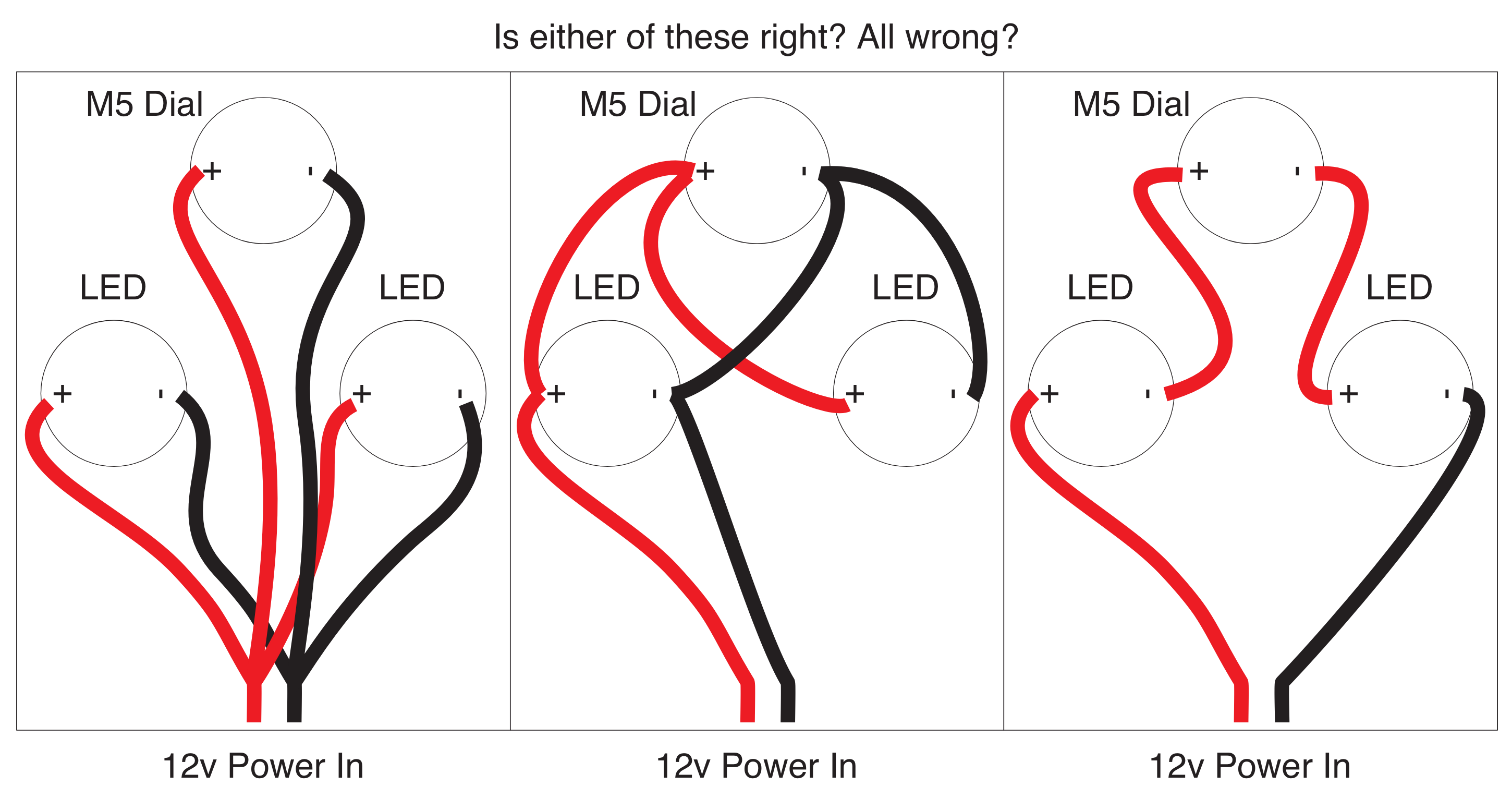
That’s an excellent point. Specifically, I’m looking for how to get continuous power to all three items. LEDs would both be on whenever the overall device is getting power.
Deleted my post as rereading what you said that sounds like what you want. I’d have coloured it the other way round but 2 should work. (red +ve black -ve). 1 should too. It’s such short cable runs it’s not going to make much difference.
Thanks! I never can remember that color schemes are different from AC to DC and what the color schemes are!
I tried option #1 and it did not work. It could have been faulty solder joints on my part, but I suspected that routing / wiring plan could be playing a part. Thoughts on option #3?
PS: I edited the coloring based on what you suggested!
Don’t take my word for it though, put 12v across the +ve and -Ve terminals to light up the LED and use a multimeter to measure voltage from NO to ground with button unpressed and pressed - should be 0. Then measure continuity, should be open circuit when unpressed and continuity when pressed.
Don’t want to fry your m5
Good points. I’m totally unable to locate my multimeter, and I’m kinda sick about that.
PS: after having it wired up as shown in option #1, and the dial not being lit up, and only 1 of the two LEDs being lit up, I took it apart, and re-uploaded the firmware (because of having forgotten to do a bug fix that was listed in the docs) and the dial was not burnt up, still working.
I’m actually “thinking” (which is dangerous because I have no training as an electrical engineer) that option #3 makes the most sense, although it did not occur to me at all last night while trying my first effort.
Hold on a sec. I haven’t figured out what you’re doing yet, but 3 is unlikely to ever be correct.
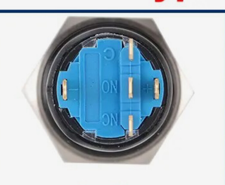
So I have buttons like these on a toy car I made and I just nipped out the garage and unfortunately I’ve none left to check with. But from memory if you bridge + and C the lights always on and if you bridge + and NO it only comes on when closed.
BUT these were buttons that are powering LEDS so when closed current is flowing THROUGH the button which in this case I don’t think you want, you just want open/closed.
@Dreyfus, thank you so much. The buttons I show 4 solder terminals on the bottom. A + and - for the LED, and then two others for the momentary switch’s state. I was planning for the power to the LED to have no connection to the switch’s function.
Are the LEDs you have intended to be run from 12V or are they bare LEDs? I’m guessing they’re probably intended to run from 12V directly if they’re inside switch buttons, but I would definitely verify that before wiring anything up.
As @Dreyfus suggests, testing things separately is the way to go here if you’re not confident. Wire a single LED up and verify that works. Wire up the other LED and verify that works. Wire up the dial and verify that works. Once you’re at that point, you can wire them all to the same source and you’re away.
So from looking at it, option 1 and 2 are the same, electrically speaking, aside from the wire lengths. The currents involved here are small so I would do whatever is easiest to manage from a physical standpoint. If I had a big terminal block where power was coming from and the wires were relatively short, I’d do 1 because it’s more flexible and more ‘obvious’ to troubleshoot, I guess. If I had a long run to get to these items and cable management was an issue going back to the power supply, I’d do 2.
Option 3 isn’t going to work because if the M5 dial needs 12V, it won’t be getting that. It will be getting something less because there will be voltage drop across the LEDs. How much voltage drop and how bright the LEDs will glow becomes the type of annoying problem that would require some algebra to solve which means it’s almost always going to be the wrong answer when the question is ‘is this device powered properly?’.
I wired up both switch’s LEDs before the install, and both worked. I know the dial is good (from it powered up from USB while uploading firmware), but I had not yet powered it up from the power socket on its back. I should be able to do that easily.
Thank you so much. I guess at this point, as I start to rewire it again, I will be attempting #2.
What If I modified option #3 so the dial was the first thing in the series? The LEDs are capable of a wide range of voltage, including lower than 12v.
…Or maybe I’m not understanding voltage drop. Does the first device in a series not suffer voltage drop? Or does a whole circuit of multiple devices wired in series all suffer the same voltage drop simultaneously, like a traffic jam that affects all the stacked up cars?
I’d be tempted to start with #1 just because that way it’s super obvious. Everything is on its own wire, everything goes to either + or - and is separate. If you think you’ve got a good handle on the connections then go for it, but I’d personally default to #1.
Ah, so that’s an important point with loads in an electrical circuit, it makes no difference. This is because current flows in a loop and the magnitude of that current is based on the voltage applied and the resistance of the loop. To work through an example:
If you have 2 resistors in series, say each being 500 ohms then their resistances combine to be 1000 ohms. If you put 12V across that, I=V/R means that you get 12/1000 amps or 12 mA. If you want to know the voltage across each resistor, you can then do V=IR to get that voltage. Each voltage is 500 * 12mA = 6V. This makes sense, right? It’s a voltage divider with 2 equally sized resistors, so equal voltage across each.
If you change that situation to one being 100 ohms and the other being 900 ohms, the total resistance of the loop is still 1000 ohms, so there’s still 12mA flowing in the loop. The difference now is that the 100 ohm resistor has 10012mA or 1.2V across it and the 900 ohm resistor has 90012mA or 10.8V across it. both still add up to 12V, of course, but the share across each resistor is different. If you wired this so it went +12V, 100R, 900R, 0V then the point between the 100R and 900R resistor would be at 12V - 1.2 = 10.8V. If you wired it so that this went +12V, 900R, 100R, 0V then the point between the 900R and 100R resistor would be 12V - 10.8V = 1.2V. Same voltage across each, it’s just re-arranging where the voltage drop is.
So in any case with the LEDs, having them wired in series with the power supply line will mean that most likely nothing will be powered correctly. If the M5 dial uses no current (the same as saying it has a very high resistance), it will probably work at least reasonably well because it has all the voltage across it, but that’s because there isn’t enough current in the LEDs. If the M5 dial uses a lot of current (the same as saying it has a very low resistance), it won’t work but the LEDs will light because all the voltage will be across them. They would only light dimly because they’d be running at half voltage each, but they’d light.
So yeah, there’s no way that this ends up working as you want by wiring them in series like that.
OK, thank you so much for taking time to explain! It seems my default choice to try #1 was not a bad idea to begin with, and any lack of function was possibly down to bad wiring connections.
Yeah, and that’s always the challenge when starting out. It’s common for things not to work and when you’re first developing skills it could be down to any number of things. Once you’re more familiar with electrical stuff you’ll find that things like issues due to poorly made connections will mostly go away and things will behave a lot more reliably. You’ll also be more confident with trouble-shooting, so you can identify those kind of issues quicker if they do arise.
It’s the old problem of the people most likely to make basic mistakes like poor solder connections or overheating/damaging stuff during soldering are also making those mistakes because they’re the ones least well equipped to identify those kinds of failures. That’s a thing that repeats in almost every situation, really. The novice will be trying to develop their skills while likely using poor equipment and being unsure of what is important or not. The expert has good equipment but can also easily identify/fix the issues well enough to do a good job with crappy equipment. The challenge is getting from one to the other without going mad ![]()
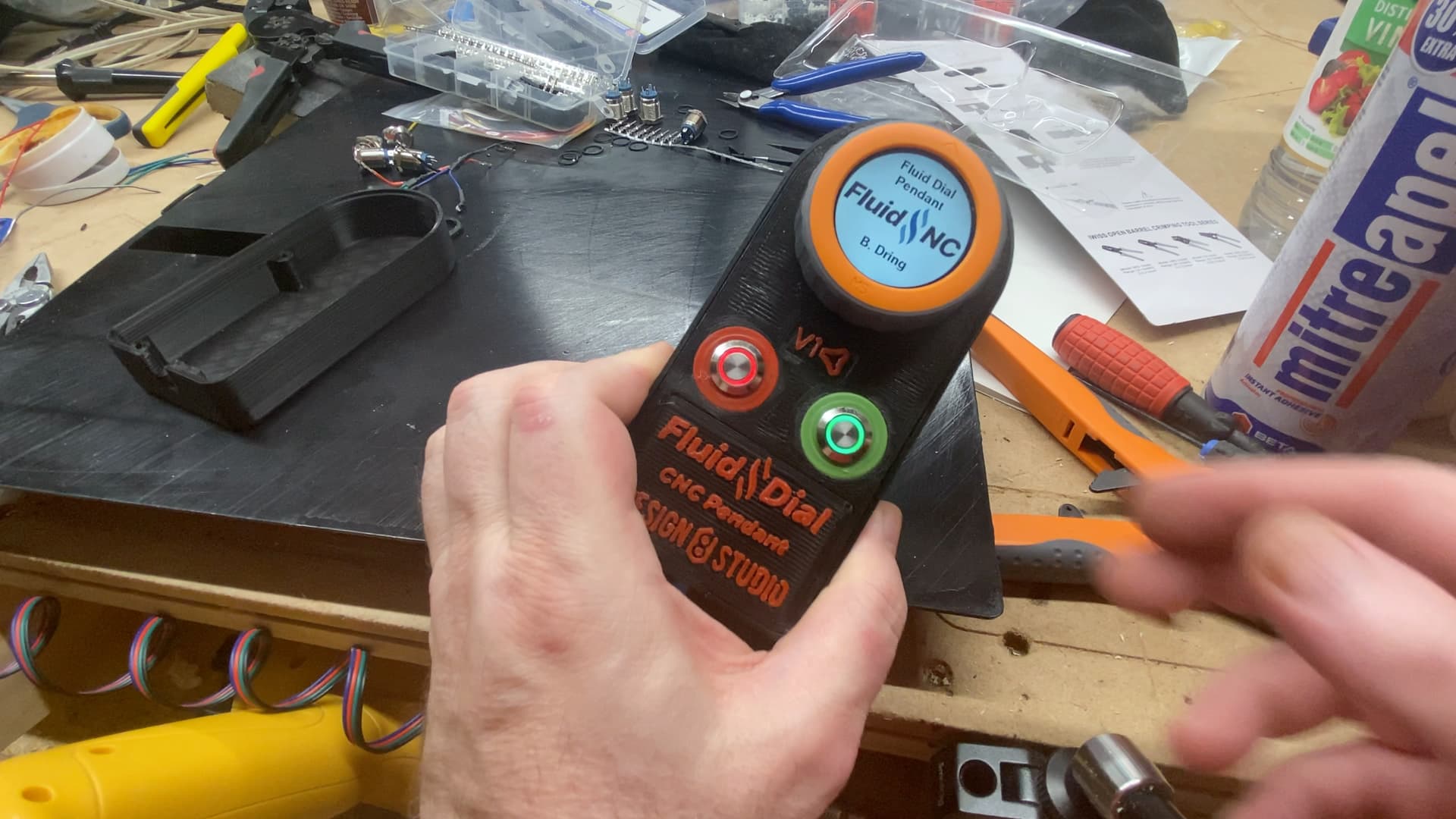
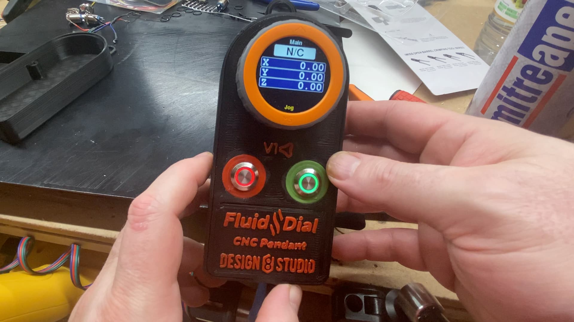
Please forgive the double post, but I wanted to circle back and report success on the rewiring. As posted on the original build thread for the pendant:
I did have to redo the wiring in the pendant. I found I had misaligned one button such that I connected the DC power wires for its LED to its momentary switch terminals instead (and vice versa). I also had no power to the dial, for some reason, probably because there was a very tight fit between the dial and the bottom of the base, which caused pressure against the wiring connector I was using. This led me to remix the base to add depth, and re-print it, while I was redoing the wiring. Now I have success.
Still need to get it wired into the board.