I’ll report back on the new slider when I get a chance. Kind of a pain to swap that out because of the servo but hope to have it swapped and tested sometime tomorrow. I really didn’t want to go with the glue option.
I noticed I had a bit of binding and realized that I used a socket head M2 instead of a button head for attaching the Z switch like it says in the instructions. It’s fine for the one hole but not the other. I didn’t have M2 button heads so I just took the Dremel and ground it down a bit but can still get a hex key in there to tighten it.
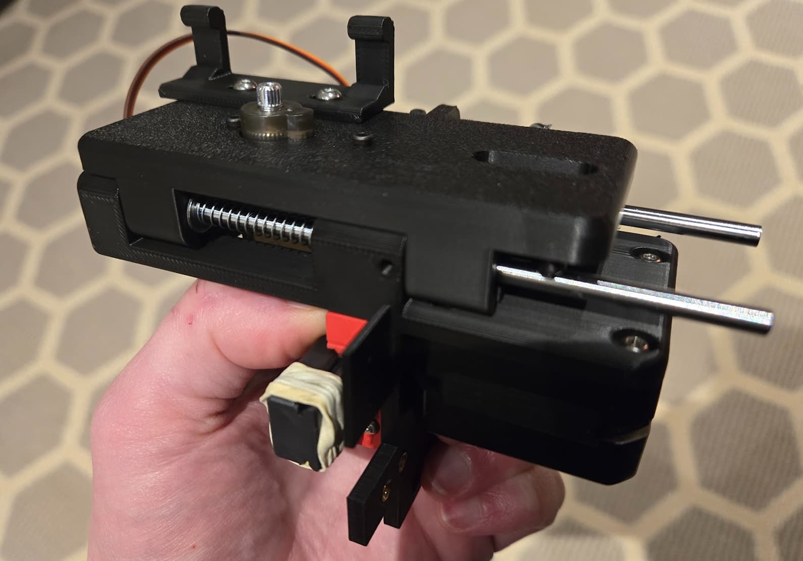
I thought it was binding a bit at the top, but I think that’s just how it works with the Z motor and the lifter arm. It locks it at the top. Otherwise, it slides very smoothly. I understand about the spring needing to apply light pressure. That’s a pretty delicate balance. It’s enough to force it to the bottom when sideways but not if upside down.
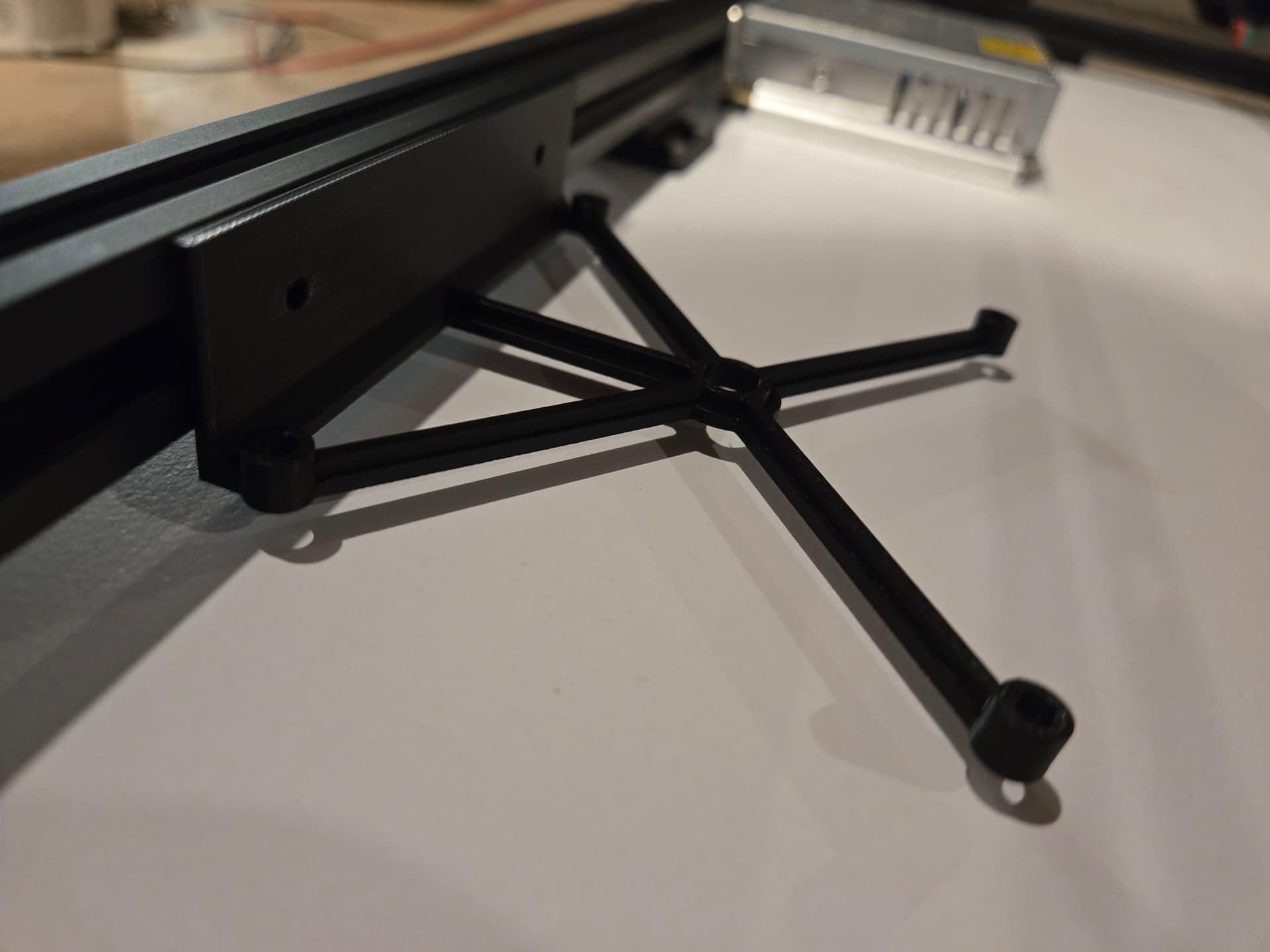
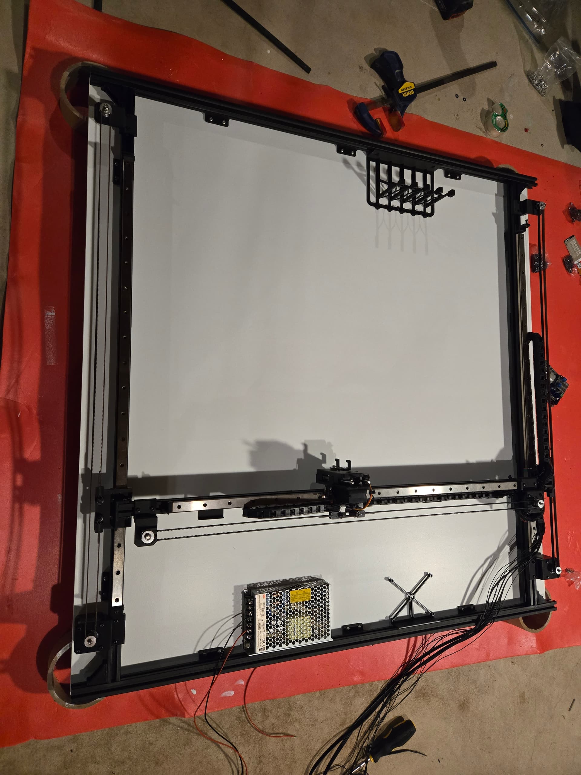
I want to mess around with it a bit before wiring everything up, so I figured out that I can slide the MGN15C carriage off the end onto the plastic rail it came with if I remove the Y-Axis idler mount and the stop bracket. This lets me assemble the whole thing on my desk, connect it to the Jackpot and generally just fiddle with it. I generally see how it works, but curious on the homing and connecting some of the dots. Then I can just slide it back on the rail when done. I have just barely enough room to do so.
I didn’t notch the rods and add the set screw. The spring side rod is a little loose so I probably need to do something. I might just do something to make that bottom hole a little tighter.
Maybe I’m just putting off wiring. That’s the worst part of any project for me. Getting 9 wires into that smaller drag chain which you can’t open up should be fun.
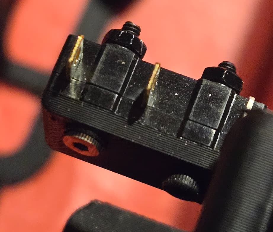
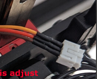
I should probably make connectors, especially for the pen holder wires. I have the stuff for dupont connections but it seems like locking ones would be better. What kind of connectors are these? JST-PH 2.0?
The only downside I am noticing with the new slider is a slight “tick” during pen lifts caused by one of the bearings hitting the flange. Since most of the stuff I have plotted haven’t had much Z travel, its not a problem, but I am currently plotting something with 27,962 pen lifts and it’s bothering me (I live out in the woods and I can hear a mouse fart in my house).
Ideally, it needs to be re-designed with a constant force spring. Maybe someday…
I have some stuff called FUN-TAK by Loctite left over from another project. It’s really sticky but never hardens. I was thinking a tiny ball of that in the bottom hole before inserting the rod might do the trick.
Actually, there are 11 wires. Don’t forget about the Y Axis switch. I used 22 gauge for the 7 stepper and servo wires and 28 gauge for the 4 switch wires. Wasn’t too bad. Taped the wire ends together, straightened out the chain and used some fine point, angled tip tweezers to help the bundle through.
Yes, that’s a JST-PH. The end attached to the servo wires is designed for a PCB, but it is what I had on hand. I recommend you definitely make a conveniently located connector for the servo at the very least. I think a Dupont would work fine for that instead of the JST. It has taken me a while, but I am finally comfortable crimping on those microscopic connector pins. However, I did solder the 4 switch wires and that has worked fine.
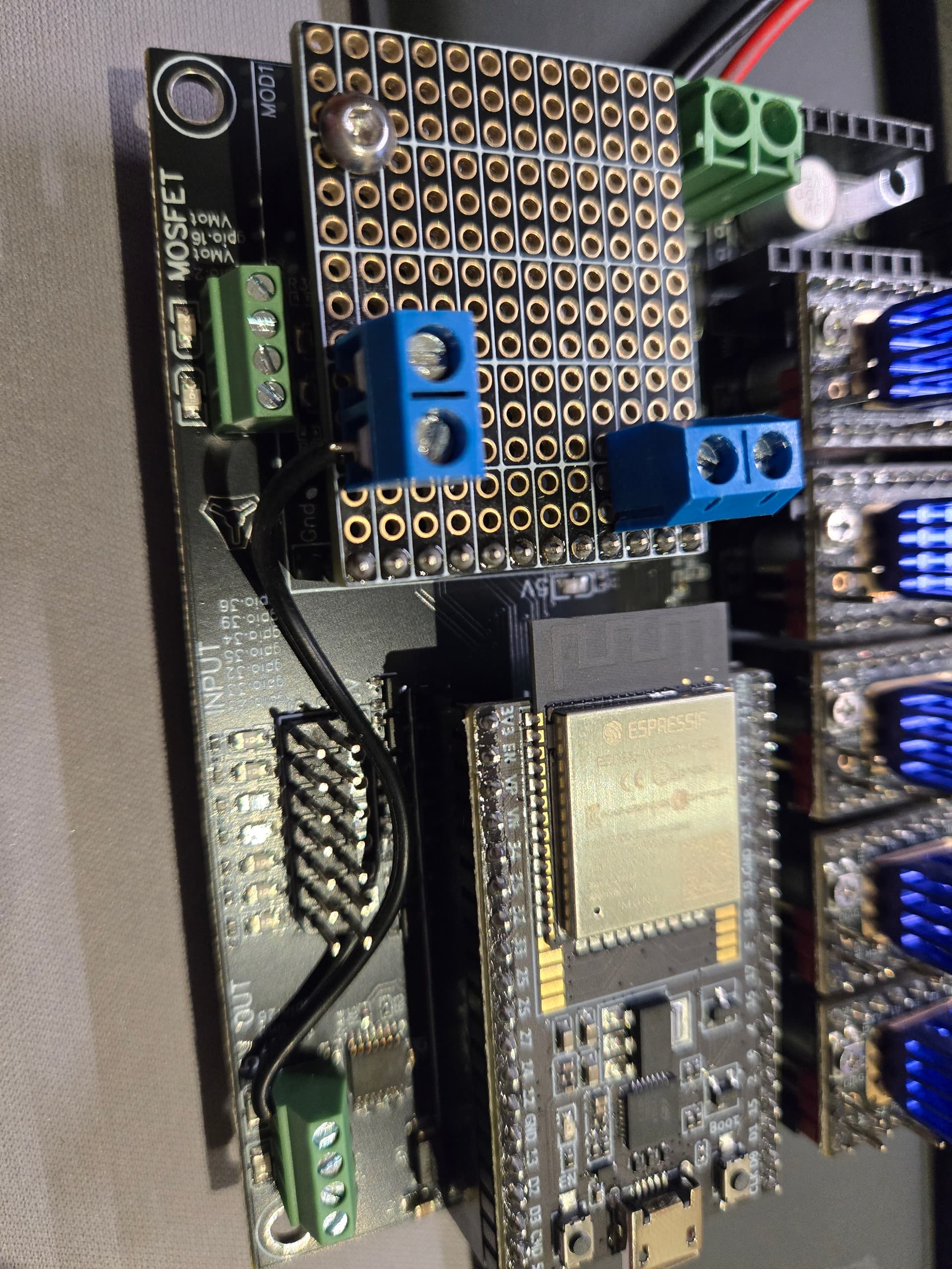
Hmm, I’m thinking about getting one of these modules to clean up the servo wiring a bit but it’s a bit overkill for a single servo. It also appears to be simple enough that it implies that one of the pins for the expandable module could be used. I’d just like to have the 3 servo wires connected in the same place if reasonable. I’m not sure what the best way is to hook up a servo to a Jackpot.
I don’t see any added value by using one of those breakout boards in this situation unless you don’t want to make a simple connector like I did. Seems like the purpose of those boards is to give you a convenient way to multiply the 5v and GND connection on the expansion port by 4, so you have a separate power connection for each device. It also gives you a convenient way to allow an alternate 5v power source. You have no need for any of that. If your goal is to keep all 3 servo connections together, you will want to use GPIO 14, 5v and GND on the expansion port, and the boards you are looking at will do that…
BUT - the logic level on the servo signal wire might be a problem if you use GPIO 14. The logic levels on GPIOs 26 and 27 have been shifted to 5v (that seems fairly obvious based on the markings on the Jackpot board). I assume that the GPIOs on the Jackpot’s expansion port have not, so they are at 3.3v (Maybe Ryan or someone can back me up on this). I’ve read different things regarding the required logic level of the MG90 servos. Some say 3.3v works fine and some say they need 5. Probably depends on the servo (the cheap knockoffs don’t always work the same). Regardless, it wouldn’t hurt anything to try it out, and you will definitely want to do that before buying (or making your own) expansion board.
To try it out, hook up the signal wire on the servo to GPIO 14 on the expansion port and change “output_pin: gpio.27” to “output_pin: gpio.14” in the “besc:” section in config.yaml. If it works, then use one of the boards in question, or make your own connector.
The important thing to consider here is the logic levels of the GPIOs (on the expansion port) on the Jackpot vs. the 6 Pack Controller (for which the boards you linked to are made for). I haven’t looked at a schematic of the 6 Pack, but based on the documentation, the logic level on the GPIOs on the expansion port have been shifted to 5v. I don’t see that happening on the Jackpot schematic. I could be wrong, so someone needs to confirm this.
If it turns out that the servo needs 5v logic and the Jackpot expansion IOs are only 3.3v, you could still get all the servo wires together by designing your own breakout board with level shifting on it. And, if you did that, I think we can all agree that your OCD issues are way worse than mine.
I was curious so I tested it on pin 14 and it seemed to work fine. So, if you removed the connector on the left and put it next to the other one, I’m guessing it would line up with GPIOs 12 & 13. Pick one of those, change the config and you’re good to go.
Personally, I like the little green light next to pin 27, so I’m sticking with that.
The traces on those proto boards are in groups of 3 (notice the white grid printed on the top), so the connections to the expansion port pins don’t extend beyond the bottom row of 3.
Quick question. How is the Jackpot supposed to be be mounted? If you attach the printed holder to the extrusion, it doesn’t reach the board. I thought the Jackpot would be mounted by screw through Jackpot, then through the holder and into the board.
I melted an M3 nut insert into each of the corner holes which line up with the holes in the jackpot board. My boards are fairly new, so not sure if they have changed from previous versions. I do recall having to mount the holder to the extrusion before mounting the jackpot.
Ohh. Yea, that will work fine. I’m not sure why I didn’t figure that out. Maybe I’ve crimped a few too many wires lately… (but I have become much more proficient at it)