Well, it’s not my aim but maybe it should be yours. If you are wanting to do interesting, interactive stuff at schools and maker fairs, then you want the plotter to be as fast as possible. I built this plotter with a public space in mind, but it was where people wait for food and drinks, so I wanted something interesting to look at. If they caught it mid plot, maybe they’d swing by the next day just to see the result… and buy more food and drink. Stuff like that. I’d think for your purpose, your machine is perfect. All the moving parts visible, keep it small, raw and fast.
2 Likes
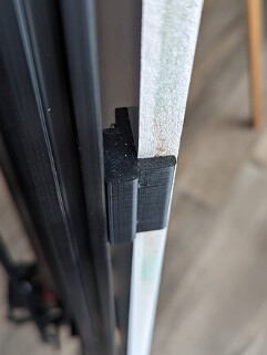
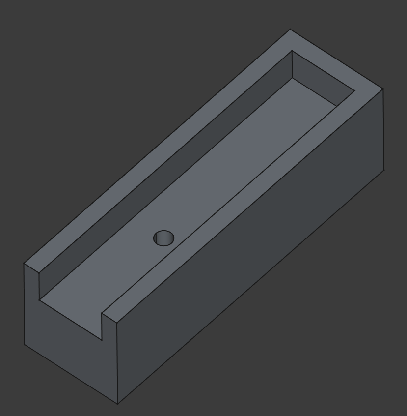
Designed a holder for a fountain pen this morning.
Gravity feed pen problem… solved!
Need for a special toolbin… created!

Pen is a Pilot Kakuno
12 Likes
What font is that? It looks great.
The font is called Headstay. I bought it for a few bucks on Etsy. They have a free download but the numeric characters aren’t included.
For anyone curious about fonts and pen plotters, I know way more than I care to. Basically, there are very few fonts out there that are easy to pen plot without lots of manipulation with code or a font editor. In a nutshell, all the paths (vector definitions) that make up a font’s glyphs must be closed (start and end at the same point). That doesn’t translate very well to a pen on paper. The reason I chose this font is that it is a true “single line” font, meaning that it defines each glyph as a series of lines and curves and when it gets to the end, it retraces itself (exactly) back to the beginning. That way, it adheres to the font standards of having a closed path, but the appearance is a single line. I still had to write the code that detects when the glyph starts retracing itself and omit that part from the tool path so every line isn’t drawn twice. I worked on this for quite a while and I only wound up with 4 or 5 fonts that work correctly on the plotter.
4 Likes
That makes sense. I know Bob did some tricks to take the line segments from the fancy text in sandify and break them into line segments and then order the segments to reduce redrawing.
Writing text with a pen plotter appears to be quite the rabbit hole.
I stumbled across “handwriting synthesis” which seems like it could allow for more natural writing. I saw another project generating gcode from this output.
There’s a demo here. Slow the speed down and you can watch it.
8 Likes
I got the 2020 extrusion, rails, and some other hardware so I’m wrapping my head around some things before I get started. I think this is mostly because I’m downsizing it so I’m not working to a factory 49" width.
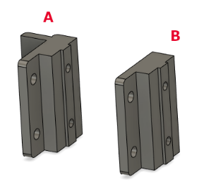
I printed one of each A and B so it’s helpful for me to visualize how this works. My plan for now is to print everything in PLA with a 0.4mm nozzle, 0.2 mm layer height, 3 walls, 75% infill, 6 top and bottom layers. I’ll adjust settings/filament types as needed along the way. At least for these pieces that’s more than strong enough.
On the frame, it seems that with part A, there’s not really any wiggle room with having the board width exactly correct. I suppose as long as the vertical sides of the back board are at least parallel (which I’m confident I can do with my table saw), it should be fine, and I could measure the X gap before cutting those extrusions.
Alternatively, I think I could just use part B instead of A. This would mean the back board should be about a half inch wider since they offset by about a quarter inch as shown in that second picture. Part A and B appear to be the same other than the lip that goes along the edge of the board.
I’m somewhat inclined to leave the back board oversized until the frame is attached, and then size it against the extrusion with a flush trim bit on my router table. I have to buy a whole sheet of MDF either way even though I only need roughly 3 feet by 3 feet.
I’m in no hurry here. I expect it to be a couple months until I have a functioning machine.
1 Like
That all sounds good. Print settings should be fine. As long as the frame is square and you’ve got it mounted firmly to the back board, either A or B will work. MDF likes to tear, so predrill the holes.
The blind extrusion joints don’t always want to seat up perfectly square so they might need some help from the mounts.
1 Like
That Calligrapher AI project is very interesting. I must admit I got lost pretty quick trying to read Alex Graves paper but the demo is cool. This is as far as I got with the fonts.
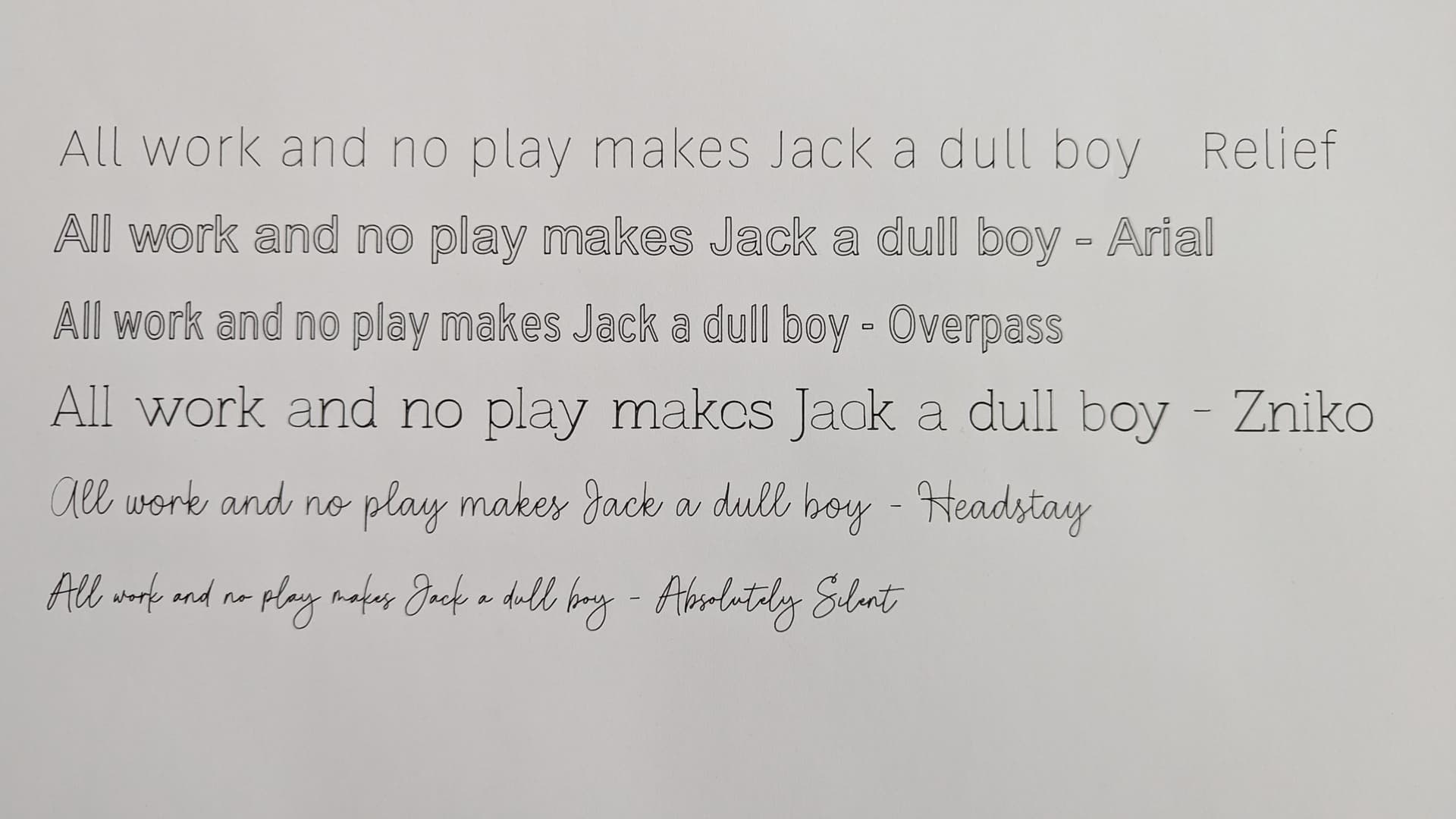
The first one (Relief) is a nice generic single line that works well (although I see I didn’t get around to editting the dash (-). The next two (Arial and Overpass) are examples of unmodified tt fonts. They are great as long as you want the double line look and you don’t mind the extra time it takes to draw. I started modifying Zniko but lost interest. You can see how some lines are darker (drawn twice) and the e and c are not right (that is common). And the last two are true single line fonts that I already mentioned. Although I still had to modify a character or two because the “backtrace” definitions had an error.
Rabbit hole. Yeah, that’s a good way to describe it. I did all the coding in Java because that is what I am most comfortable with, especially for web app stuff. I looked briefly at converting it to Javascript, but some of the objects I used in the Java program don’t exist in JS. On the other hand, I had to do most of it manually since there were no libraries out there for Java, but I’m guessing there must be a JS library that does the same thing that I did in Java. Which was essentially to import the ttf font file, parse it into separate glyphs, read the glyph definitions (they are each a series of Bezier curves and straight lines), sample points along the curves and convert those points to gcode.
6 Likes
Wow. Stopped at Michael’s for a different reason and was looking at pens. Didn’t realize there were so many options in just Pigma Micron, not to mention the rest of the aisle. I see the Staedler Pigment Liner pens too.
Any suggestions on tip type/size?
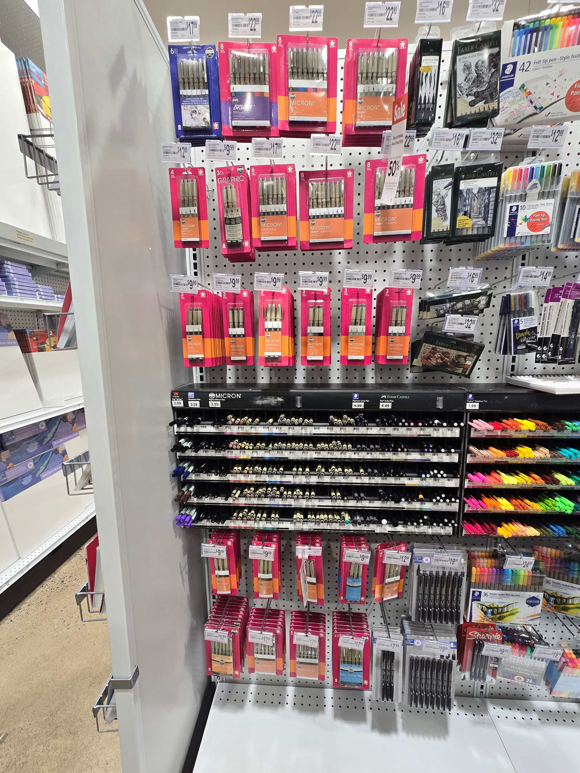
Edit: I see this shows the size. Obviously, there’s some room for experimentation here but I imagine going too fine could be an issue. I guess it could be interesting using different tip sizes on the same drawing, even if it’s the same pen.
I go with the Pigma Micron Fine Liner 05 (.45mm) for most stuff.
You can get the black ones on Amazon for under $2 when you buy a 12 pack. Same with an 8 pack of assorted colors. If you are looking for a specific color, the pricing is nothing short of insanity. At one point, Michaels had a decent online price for Sepia pens, less than $3 each, but then you look the next week and they want $8. It’s insane.
The Uni-ball Powertank cartridges can be had for less then $1.50 each on Amazon. I’ve found it cheaper to buy a set of 12 (complete pens) and remove the cartridge. Again - insanity pricing. You’d think you could get a box of refills for less, but no, cheaper to buy 12 and throw away the housings. Make sure you get the retractable style (they have a metal ring towards the drawing end as seen in the above pic just above the blue plastic tip).
For a cheap alternative, I do have a holder for the “Mr. Pen” knockoffs found on Amazon, but they run out much quicker than the Pigma Microns, so I abandoned them as an option.
2 Likes
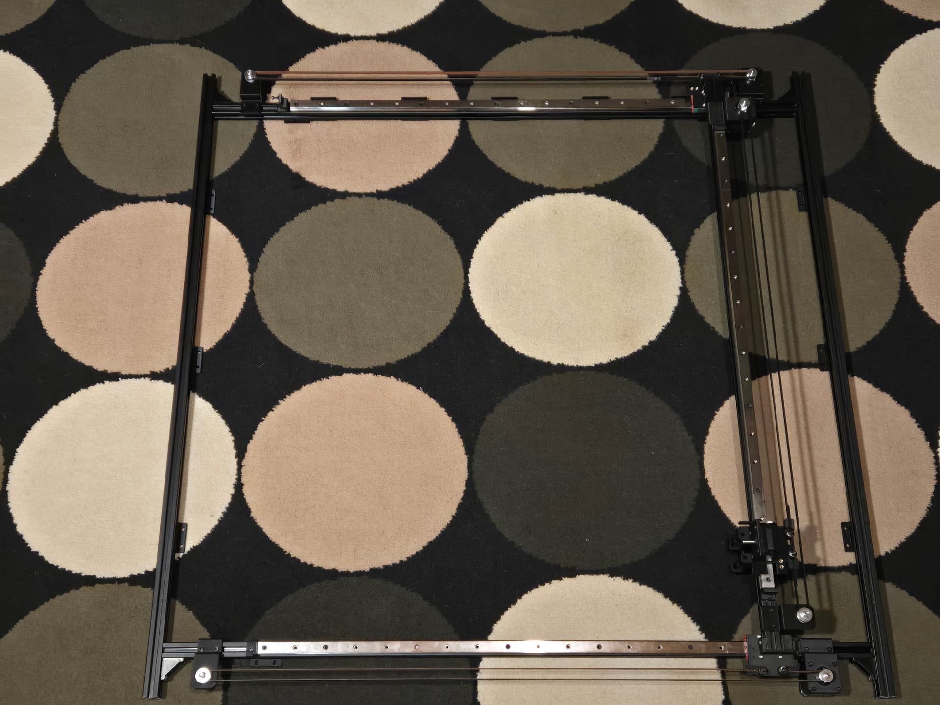
I’m looking for a couple measurements to validate my resizing. I have some time this weekend to work on the frame anyway.
What’s the distance from the right end of the rail to the inside of the right vertical frame extrusion?
What’s the distance from the top end of the extrusion to the rail?
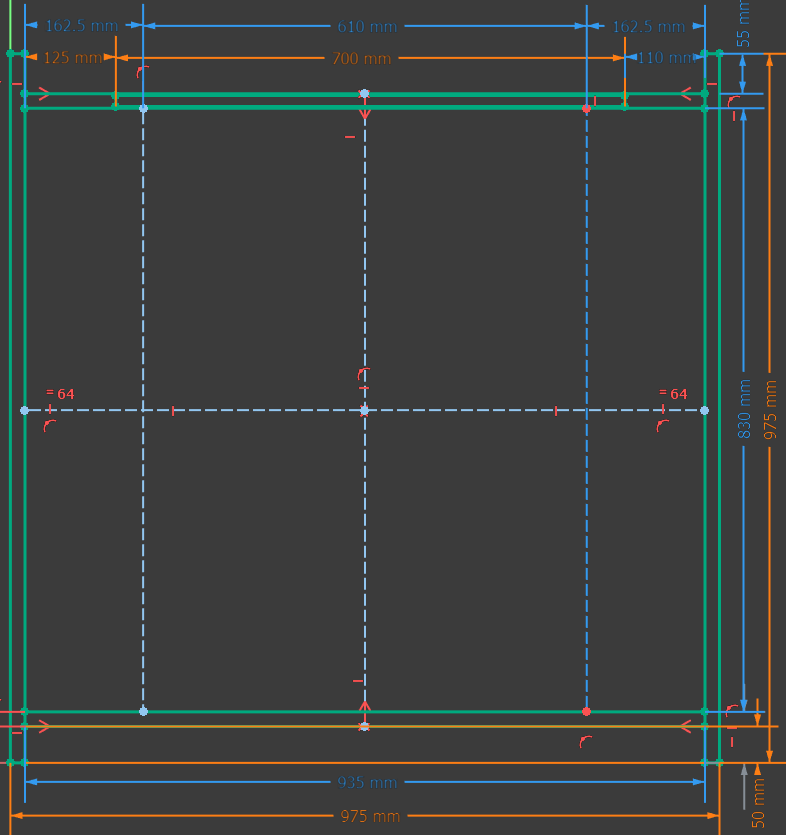
I’m using 24" paper, with 700mm rails, and have 1000mm extrusion. These are my calculations currently. I’ll be making some slight tweaks. I’ve done some rounding and conversion so everything is in mm. My intent is to have the Y-axis extrusions reflect the full height of the backboard with it providing some protection at the top similar to the bottom. I don’t show it here but the Y-Axis extrusion length is 49mm longer (we’ll call it 50) than the inside distance between the top and bottom horizontal extrusions.
1 Like
On my 36" plotter it is 100mm
On my 30" plotter it is 95mm
The 5mm difference is simply due to the length I cut the rails on the 30". With 95mm, the X-Axis motors have 35mm of wiggle room before they hit the right vertical frame extrusion. I don’t know where your rails fall in the equation, but you should be good down to 70mm (distance from the right end of the rail to the inside of the right vertical frame extrusion) if you want to avoid cutting them. At 70mm, the gantry is over the Jackpot, which is fine as long as the wires connected to the stop switches are arranged so they don’t interfere with the underside of the gantry,
If my math is correct - a 700mm rail should land you around 100mm, which is perfect.
Edit: I see now that you came up with 110mm. Even better.
105mm
1 Like
It all checks out. Thanks!
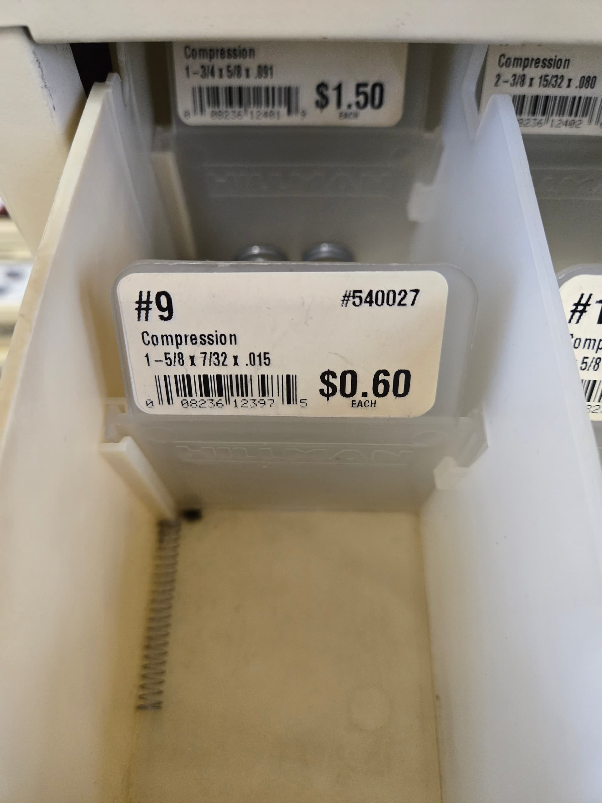
For anyone trying to source this, I found it at my local Ace Hardware store. It’s a Hillman #9 compression spring (SKU 540027). I feel like this is probably the trickiest item in the BOM to find.
shop.hillmangroup.com/ccrz__ProductDetails?sku=540027&cclcl=en_US
I was originally going to use a 1-1/2" x 7/32" spring that I found in my spring assortment kit, but the intended spring is significantly easier to compress than that one.
1 Like
Just wanted to say my build is going smoothly and it’s been an enjoyable experience. Here are a few notes I wanted to make while I was thinking about it:
I agree with waiting on attaching to the backboard. There have been times where it’s been helpful to have access.
Just a BOM note that you need 3 M5 locknuts. I got those at my local hardware store.
I had to do this for the 3 larger steppers. I just put some bubble wrap on the shaft and used a file. It only took a few minutes per stepper.
Another BOM note. At the moment I’m using some M5 lock washers but they are a bit too big. I think I might replace them with M4 lock nuts. Either way you need 6.
When I put the belts on, I first attached the belt mount in the non-slotted hole. Then when I wrapped it around, I adjusted the belt so that proper tension (or what I think is proper tension) was at the end of the slot. I’m not sure if this is easier or not, but I felt like it gave me good control on adjusting the tension, since I could adjust it one notch at a time.
I ran into this same exact thing. I bought ReliaBot branded rails on Amazon that came with MGN15H blocks and got a MGN15C separately. When I put the MGN15C block on, it was too tight and didn’t slide smoothly. After replacing the balls, it slides great. I thought this was going to be a pain, but it was easy. You just slide it off the end carefully, and there’s a wire that holds the balls in place. I used a pair of tweezers. It was interesting to see how they worked. I didn’t realize there was a loop of balls on both sides.
My only experience prior to this using aluminum extrusion was putting together my Ender 3. Wow, these are so much easier to use than the standard T nuts. The extrusion I bought included some corner brackets which I added since I had them. They used the standard type and they’re a pain.
Another BOM note is that you need some M3x8 socket head screws. The kit listed in the BOM doesn’t include that size.
4 Likes
Glad to hear the build is going well and thanks for the feedback. Was curious how the 3d printed parts were working out. As I mentioned, I printed all the frame mounts, trucks and motor mounts in ABS and I assume you are using PLA. There can be a slight size difference between the two and I was wondering how things like the motor mount holes and the trucks (to MGN15 blocks) holes are lining up. Also, the belt mounts and idler mounts?
Edit: Good call on those extrusion brackets. Much easier than blind mounts. Are those 3d printed? You might want to upload models or link to parts for future makers.
I haven’t had any issues. Yes, I’ve printed everything in PLA. It all lined up perfectly.
The only thing I modified were the holes for the brass nut inserts. Note I have never used these before and I did a bit of practice on those Mod 1 X-Axis Stop Bracket for Homing Switch. They were a quick print. The small end of the insert didn’t fit in the hole, so I drilled them bigger with a 4.5mm bit. I also slightly chamfered the hole on both sides with a larger drill bit. This kept the plastic contained yet I think the hole was still small enough to have good strength. Without doing this it made a bit of a mess and got plastic inside on the threads. I wasn’t able to use the tip that came to put them in, but just used the regular tip on my Pinecil soldering iron. Setting it to 240 C seemed to give me time to position it without melting too fast.
Oh I actually did blind joints first and just added them since I had them. The brackets were aluminum and came with the extrusion I bought. While the M6 tap and 5mm hole was appropriate for the extrusion I got, it sounds like some extrusion would use an M5 tap.
I was pretty careful to try and make everything as square as possible. So, when drilling the holes to access the screw, I did make some quick jigs to make sure I drilled the hole in the right spot with my cordless drill.
Today I’m working on the pen holder. I did want to note that I bought cheap LM4UU bearings on Amazon, but I bought a 12 pack. I went through 7 before finding 4 that worked smoothly.
uxcell 12pcs LM4UU Linear Ball Bearings, 4mm Bore Dia, 8mm OD,12mm Length, Linear Motion Bearing for CNC Machine Tool 3D Printer
I also bought these “linear motion rods” and they seem to be fine. I couldn’t cut them with a hacksaw, had to use my Dremel.
uxcell 2 Pcs Linear Motion Rod Shaft Guide 4mm x 331mm (0.157" x 13") Case Hardened Steel Chrome Plated, Metric Linear Rail Rod for 3D Printer, CNC Machine
I guess I did have a couple questions.
I don’t understand about not tightening the screws or why it needs to move around? The rods fit a bit snuggly in the holes on the “M. Y-Axis Truck (Pen Carriage)” so I’m not sure they’re moving around anyway. For me, the side with the spring is slightly less snug than the other side.
Also, are you supposed to have these set screws on both sides? I see it has the hole for it. I was a bit confused that there aren’t springs on both sides too.
I think mine are sliding fine and didn’t need to trim anything, but the bearings are slightly loose and I am a bit concerned about them popping out. I’m tempted to secure them a bit either with some CA glue or maybe melting a tiny bit of filament at a spot on the edge. I’m not concerned about the one with the spring against it.
It sounds like the 4mm rods you are using are snug, so you probably don’t even need the screws. The 5/32" brass rods I finally landed on are loose, so the screws are needed (on both sides). I found that if I tightened them against the rod even a little, the deflection it created caused the bearings to bind, so that is why I recommended to not tighten the screws too much.
I think springs on both sides would be ideal, but when I tried two with the .015WG (wire gauge?), it is too much downward force for the felt tip pens (Pigma Microns and Staedtlers) and, more importantly, the Z-Axis motor has to work too hard when it lifts the pen beyond +8mm or so. I had to increase the Z stepper amperage just to test it out. I wasn’t comfortable with the result - too much heat. If you can find some springs with a smaller gauge wire, say .010WG or less, then one on each side might work fine.
I have the same issue and have been pondering the same thoughts. I was thinking of putting a very small dab of epoxy (using the end of a toothpick) - just enough to keep the bearings from sliding out but easily removed in case it caused binding. Ideally, whatever is used, should still allow the bearings to move around. The part should probably be redesigned with a small tab or something that keeps the bearings from sliding out once they are in position.
As I mentioned earlier in this thread, the lifter mechanism is the most temperamental assembly on the machine. I still consider it a design in progress. There is certainly room for improvement.
I went ahead and made a change to the 3d model of the slider. Quick change, long print…
I am printing it out right now, so haven’t tried it yet, but I did break out one of the bearing holders from the main body and printed it out as a quick test and it worked perfectly. I added a 1mm flange to each bearing holder. The flange is filleted and allows for the bearing to be pressed in but keeps it from popping out. I printed it out with a Layer Height (Quality) of .15mm and 50% infill. Notice I only modified three of the bearing holders. The fourth (lower left in the pic) is the one that is held in place by the spring and washer. I didn’t want to change the aspect of that part of the assembly.

3d Model
slider_v2.zip (71.7 KB)