I read that as being ESD proteciton- from triboelectric effects, not back EMF at all.
The downside of the caps is exactly as described.
I’ll have a chance to go back through the data sheet maybe this evening or tomorrow evening.
I read that as being ESD proteciton- from triboelectric effects, not back EMF at all.
The downside of the caps is exactly as described.
I’ll have a chance to go back through the data sheet maybe this evening or tomorrow evening.
Electro-static discharge is not the same as back-emf. not sure why I was not making the distinction…
Good news though: a second stepper wired in series to the relay (that switches out of the circuit once the drives are enabled) was enough to get the drive to not fault, so we have a functional brake. I’ll get a second motor and wire in a coil to each of the 3 z motors that are to be braked. A similar load to the coil may be enough to get this to work… if only for long enough to trick the tmc for the switch to move.
Update: with the braking system on and a series of additional pin adapters, the printer isn’t working right. as it was homing and buzzing like the brakes were on while it was moving, I noticed the relay activation light flashing as the bed attempted to home. no bueno.
My dupont crimping skills are at fault here and I’ve removed all the extra connections to the relays until the 2 Ω resistors arrive and I can build a complete circuit that has jst-XH connections at the board so things are more solid. The dupont pins were pulling out of the connectors by the time they got put away out of sight. The process of shoving them in the chase and clipping the cover on isn’t the gentlest of processes because the chases are too full now with the extra wires. This solution will work once the wiring is robust and more permanent. The concept works when it is all connected properly. I’ll make a video of the completed system once connected and functional. Until then I need the z axis to be reliable so I can finish the automatic guinea pig feeder.
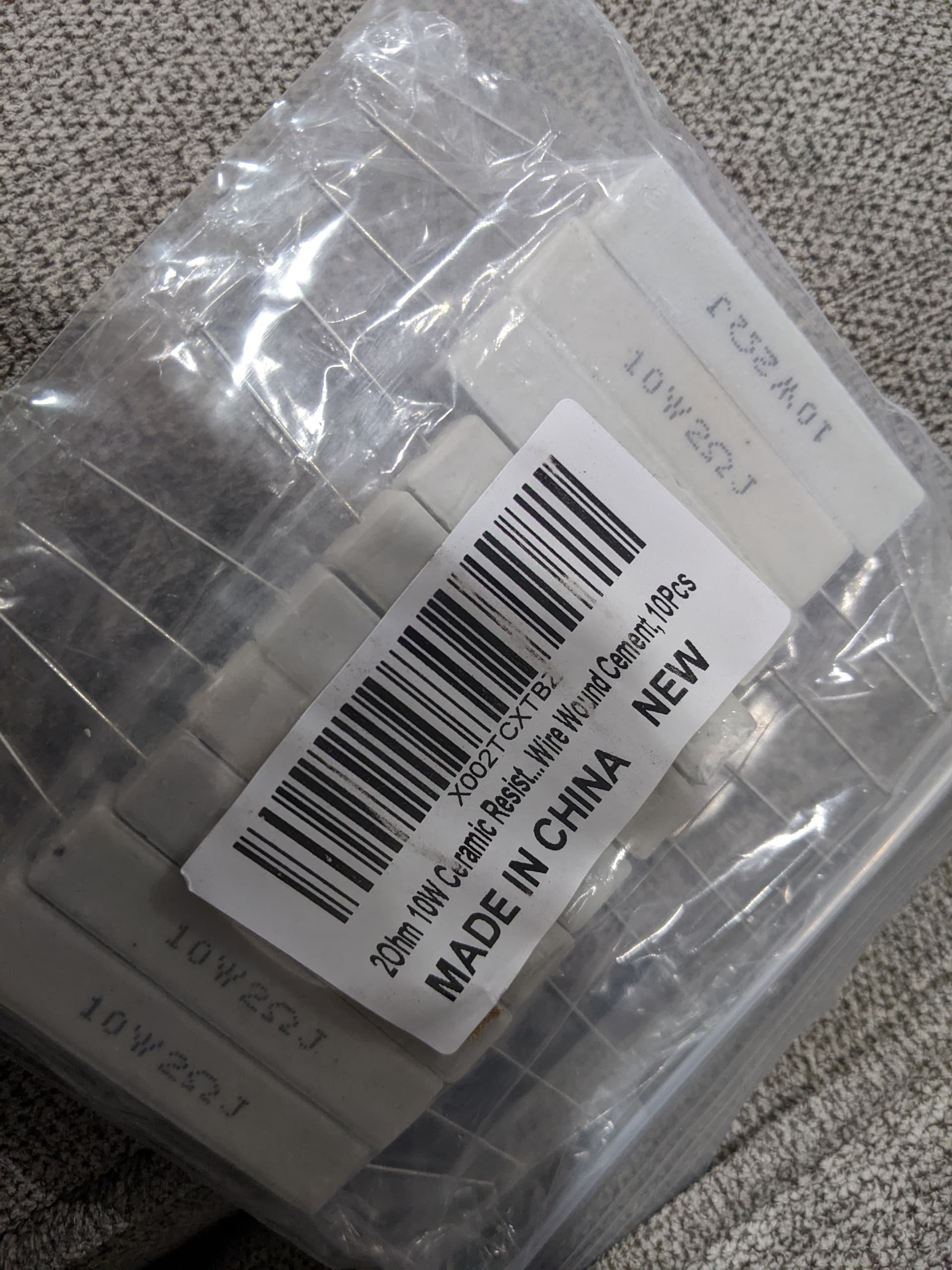
Ok they have arrived:
They were $0.80 each or something like that. I need 3 of them for this printer, 3 for the next one, plus a spare, so I have 3 that will go to someone lucky… any takers?
Have you had a chnce to put one in place as a shunt to see how well it acts as a brake?
Very interested to see how these turn out for you.
If that value works, I’m going to order the Vishay parts, as they’re much smaller though a bit more expensive.
Looking forward to pictures of your setup when it’s fully assembled.
I’ll wire it up soon. The original wiring splice job to the motor lines did not hold for long and the motors started acting weird. The wire insulation is too thick and the pins don’t go in all the way, the wires bend and then break and things don’t work right. I removed it all and it is working fine, so nothing was damaged.
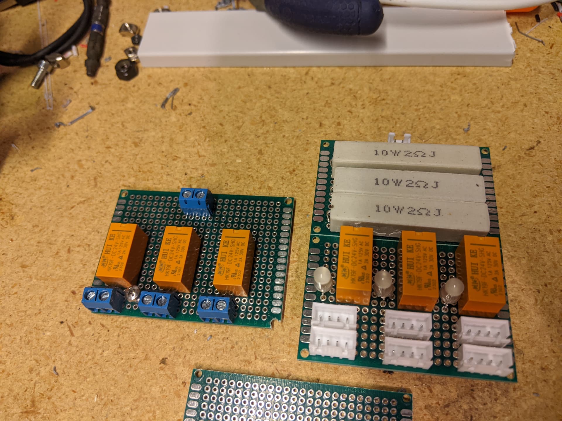
Edit: first Rev board on left, new board layout on right… not yet soldered. Thinking I’ll use straight up pin headers instead of the xh for input to avoid a complete set of crimping.
That’s looking nice.
There’s a reason the picture doesn’t show the underside…
So got it wired up and it does NOT work. The 2 Ω resistors don’t work. They are in the circuit and then out of the circuit, but the failure message is short circuit and then open circuit in the same message. Perhaps it may need a transformer coil or something to emulate a motor coil, but as it sits, this is a non-functional setup… I’ll wire in a stepper to this board instead of the resistor and see if that works like it did on the other board.
Draw us a schematic or post pictures of this.
Is your test setup using motors in parallel with the relay boards?
Without the motors in the circuit, these will cause errors for the TMCs. This is expected.
Assuming I’m reading this correctly, you may need to place an inductor inline with the resistor to fully emulate a stepper.
Thanks for the paper. I figured it was something like a tau in a n RC circuit. Figuring out what the time constant put me as a deer in the headlights. intro to EE was many moons ago. I think I’ll look for a sub 3 mH inductor and see what is readily available.
Why not just hook it up to a stepper motor, as intended?
I will for testing, but that isn’t a long term solution. 8 steppers for a 6 step system… $22 extra fit the brake?
I’m not sure I understand.
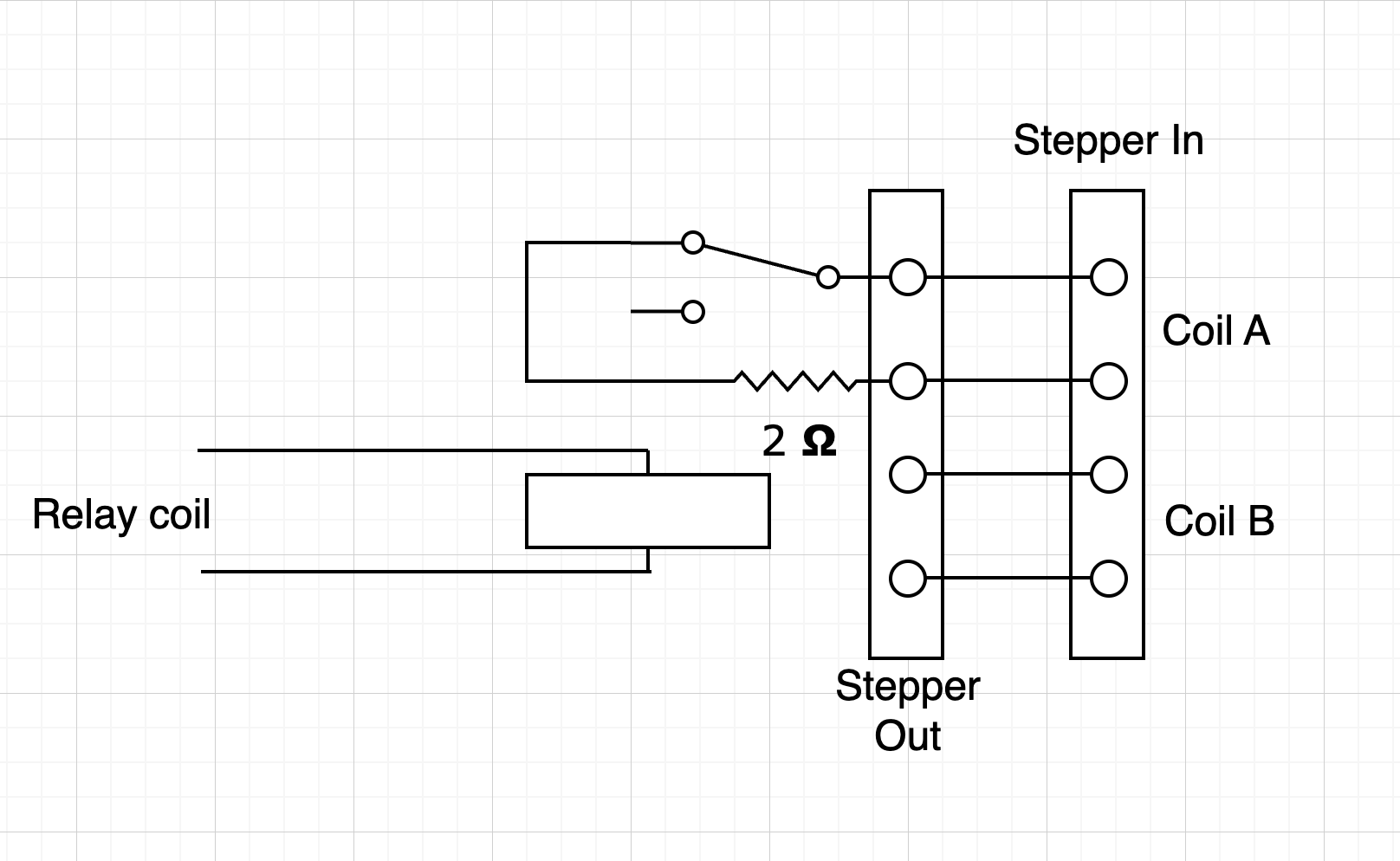
That says you need one board, with each stepper motor harness going to one connector, and an extension calbe going from the 2nd connector to the controller. This puts a brake on all three motors, using one of your boards plus three stepper extension cables (F-F harnesses).
Each set of wiring should put the two 4-pin connectors in parallel with each other. The relay then shunts on (A) on demand whenever the brake is engaged. Each connector pair is associated with one shunt relay / shunt resistor set.
When the shunts (Brakes) are not engaged, the board looks like a very short extension cable.
This would be a permanent setup.
If you decided you wanted to shunt both A/B coils of a stepper, then you’d make a board with two relays, two shunts, and one set of stepper motor connectors. You’d need three of these boards.
Edit to add- why isn’t each stepper run this:
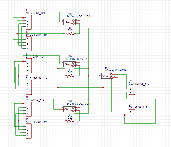
I had to get home from work to post a copy of the easyeda schematic:
What you drew is correct with the addition I have of the 5V coil relay switched by the octopus when the tmc2209 enables that switches the 24V power to switch each of the coil relays. the problem is the 2OHM resistor doesn’t work by itself and the TMC2209 detects it as a short. That leaves 2 options:
option 2 worked on the other board, but my wiring wasn’t robust enough to last and stuff kept working loose, so I built the circuit shown in your diagram for 3 motors and it does not work so we need it to be more “coil-like”
I think we are on the same page, I’m just trying a couple things while still trying to keep the printer operational. The 1.65 ohm resistor paired with a 2.3 or 2.8 mH inductor (from the pdf shared above) works to simulate the motor coil and could potentially be what is needed for a simulation circuit without having to provide the 2 extra motors for the 3 coils needed to stand in for driver startup when the motors are reactivated.
That shouldn’t be what happens when the brake is connected by itself. The TMC should throw an error because it detects an OPEN on coil B.
It should be wired so coil B is always connected to the motor. Coil A is shorted, but in its place is the resistor.
I’ve ordered an inductor kit to try some out to add in series with the resistors.
UPDATE:
Inductors arrived. I bought an amazon 1/4W inductor kit of like 200 pieces for $10. In it I found a 2.2 uH (maybe that was mH, but whatever) and plugged it in. With respect to the z brake, lego batman would say: “First Try!”
It worked and switched and zeroed where before it would error and do nothing. I’ll put in the other 2 and print something and report back, but this looks like a winner.
so red-red-black is 22 uH. I swapped it for another value and it didn’t work, so it really did work on the first try. All 3 are in place and here is the short video where I stop the bed zero early and it backs off then goes too far and fails and then you can hear the motors buzz as the bed brakes are on when it “drops” or rather lowers slowly.

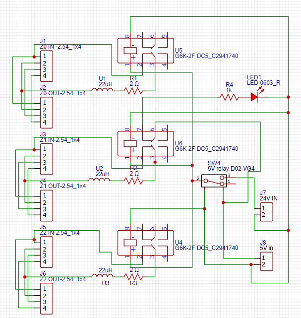
this is the circuit:
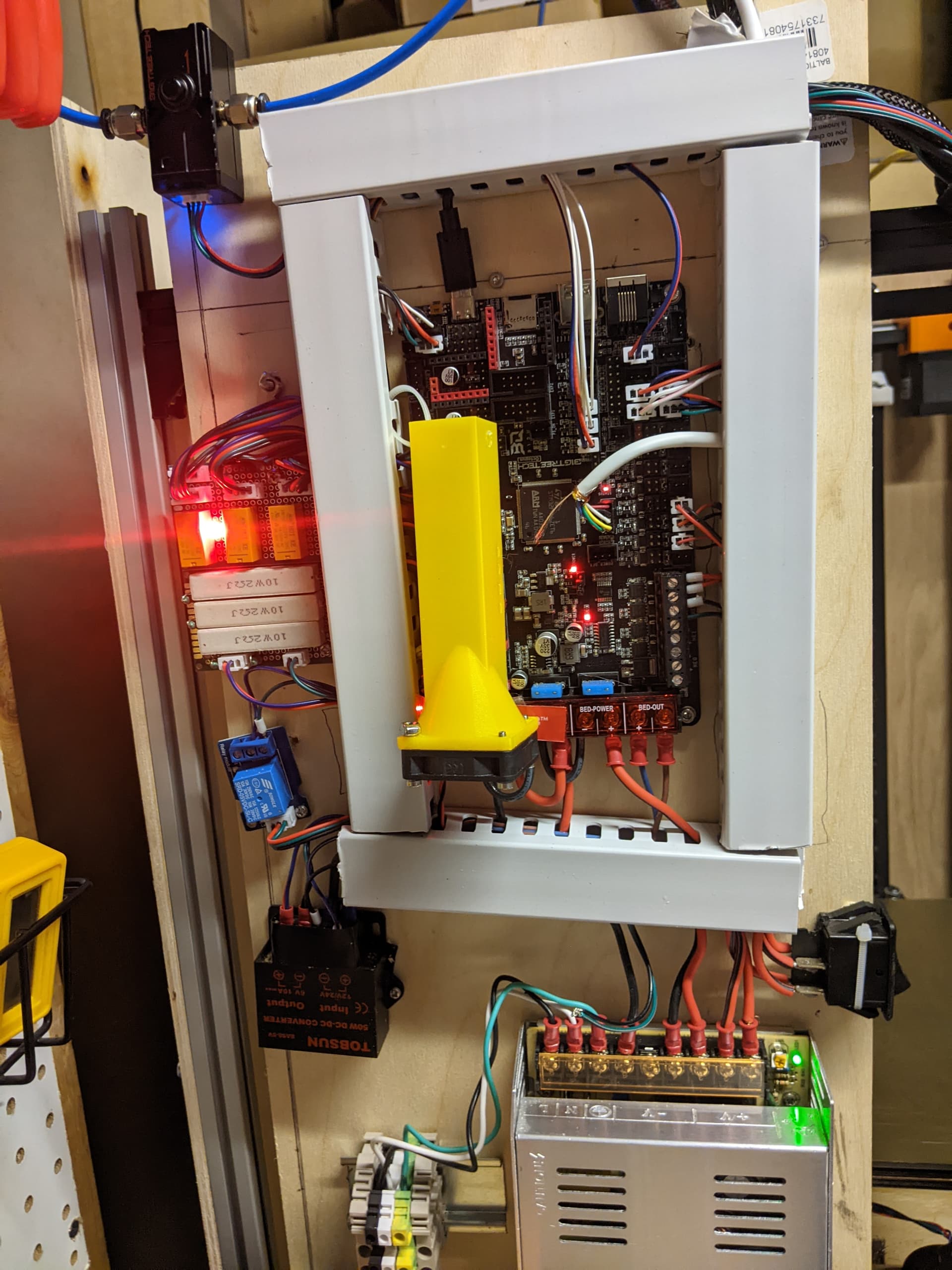
The board installed looks like this:
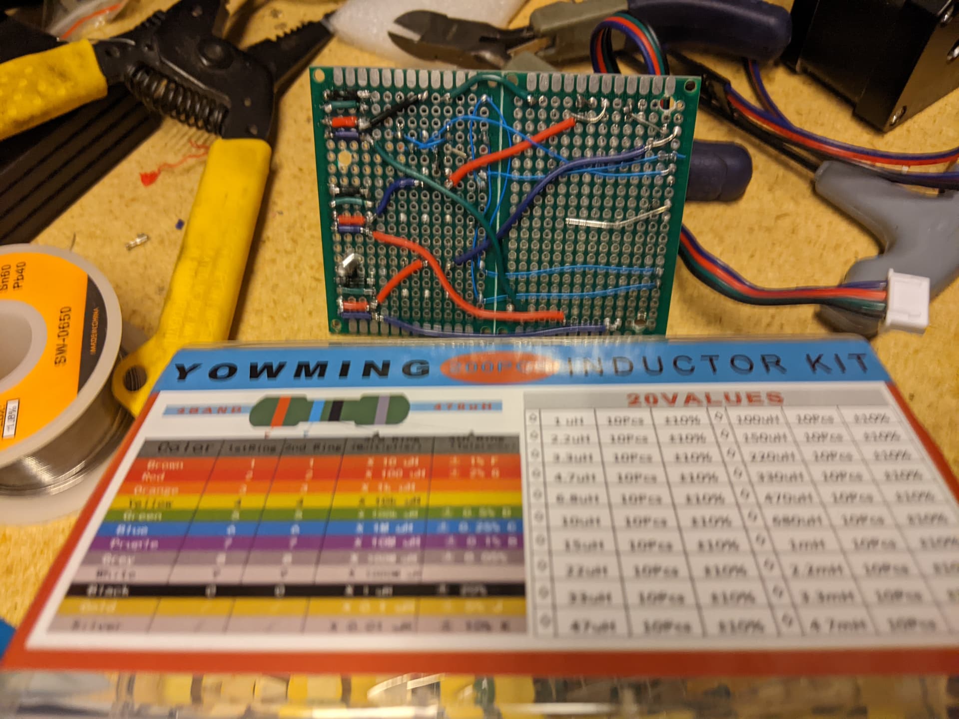
The ugly back side of the board looks like this:
Cheers for sharing Rob, that seemed like success to me? i.e. you simulated a scenario that the probe would normally interpret as a failure, and normally trigger violent plate drop? But instead, your circuit kicked in to slow the descent.
That is awesome. Now we just need this integrated into the controller PCB.
Who is playing the didgeridoo? ![]() (no didgeridoo emoji, unfortunately).
(no didgeridoo emoji, unfortunately).