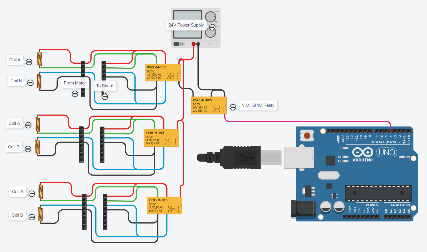
I have a BTT Octopus though and I’m wanting to trigger the relay off of an IO on the Octopus (the pink line going to the Uno in the photo because that was the only microcontroller available in the program - apologies to some that might be offended by that).
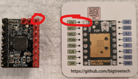
Each Z motor driver has an EN pin on the TMC 2209 board that effectively “turns on” the driver and allows current to flow to the motor. It appears that EN would be the pin to use to turn off the brake when the driver turns on… If the drivers are off, then they freewheel, and we turn on the brakes. Seems easy enough.
Here’s my question: How best to use that EN line to use the z brakes?
Scenario: the octopus processor controls the EN line with defined pins in klipper. We know what they are because we had to type them in. the processor is using 3.3V logic levels and the relay coil is 5V, so keep that in mind.
Ideas of possible options:
use circuitry (not the processor) to wire to the pin and when it goes high or low, trigger the relay to change states. I don’t know how to do this without disrupting the enable → processor pin setup.
define a pin in klipper (using the processor) as a mirror so when that EN is set for the driver, it opens the relay. Not sure how to do this. Seems like it should be possible.
use an analog input (processor thermistor 3-5 inputs are available) to measure the EN pin voltage and have a second pin output voltage to open the relay when the voltage is high enough
If you search for “arduino relay” on amazon or ebay or alibaba, you’ll get a ton of these little relay boards that have a transistor to make a low impedance input to flip the relay. They usually need 5V power and can accept 3.3V or 5V for the signal.
If you wanted a hardwired solution from the enable pin. i would solder a lead onto the top of the driver’s EN pin. That should be low risk, but if you can’t afford to lose a driver, then a software solution might work better.
In Klipper, you can define what they call a “mulit_pin”. Here is the doc:
Depends on how you wire the relay. The relay is in the normal position when not powered. When the z motor enables, the relay switches. I toggled the relay logic at the pin assignment, so it will work with however the relay needs to switch. I’ve seen various little blue “Arduino” relays switch high or low. Depends on where you get them. If low, then just ! before the pin name in the cfg file.
When the board loses power, the relay goes to normally closed.
After wiring it up, the issue is when the octopus turns on before the USB connects. When power is applied to the board, the relay energizes and the brake is off until klipper starts, then it turns on. We want the relay to remain off with the brakes ON until the motors are enabled. Once the motors are enabled, it switches off again (as expected).
I have not tested all states yet, but right now the issue is the state on power up before the firmware fully boots. I noticed this when a recompile was required with the latest klipper update. Apparently there is a custom GPIO option when you compile klipper in KIAUH to set specific GPIO pins. Not having done this before, it is unclear to me on how to do this properly. Looking into it.
Pin PG14 is the multipin of the TMC2209 enable pin. TMC2209 enables low, and the relay enables high, so the the PG14 is NOT 'd at the declaration with !.
The trouble is at board start up, it goes high z instead of low, so the relay triggers and should stay in the not triggered state.
Custom compiled klipper firmware with the specific GPIO pin state called out as !PG14 in the boot sequence makes the relay trigger now for only a couple seconds then off as it waits for klipper to negotiate and boot, but still isn’t quite right.
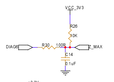
Would it kill the pin if I put a 10k resistor to ground on the signal line so it pulls down when in high-Z boot state?
For those relays you hook a power and ground to control if I remember right. Yes usually you would use positive to switch them but is there any reason you couldn’t use ground to switch it? If the driver enable pulls low then that will supply ground to the relay and allow it to switch right? Or am I thinking about this all wrong?? At work and don’t have any of it in front of me to look at lol. Going from memory and that’s shaky at best
the relay start stop logic is right to power it when the motors kick on. The problem is at initial power of the skr, the pin state activates the relay until klipper starts (don’t want this). Once klipper is going, no problems and it functions normally as it should.
Custom klipper firmware to set that pin before boot completes helped, but it still happens.
Ahh ok I follow now. I’ve seen another video where they used another pin to power the relays. And wrote a macro in klipper to have that pin disabled any time the motors were disabled. Not sure if that would work in this situation or not
I did a " mulipin" which is basically a pin clone of the motor enables pin. If it changes, the other one does too. I have it set for opposite logic so the relay does the right thing, but that part works fine.
Microcontrollers put pins in various states on startup. they are all at zero with no power applied, but when the processor powers up, it sets the gpio to a known state which is typically high resistance so the pins don’t drain a ton of current and fry.
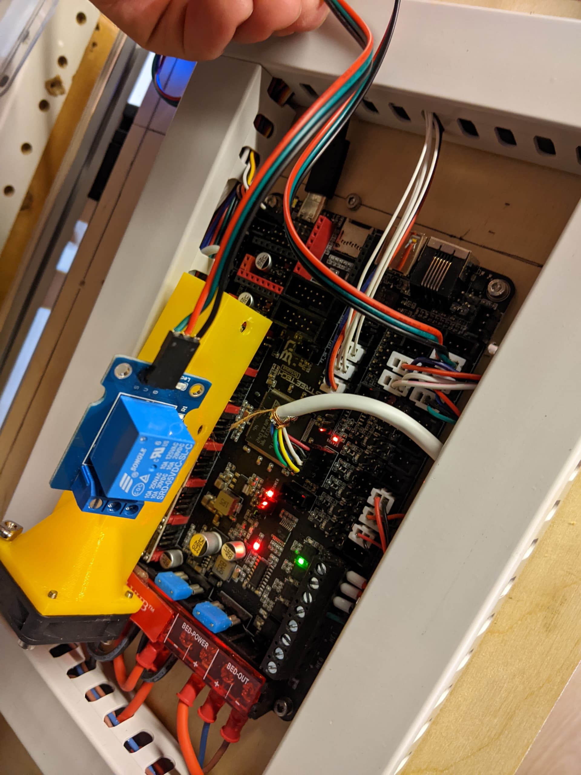
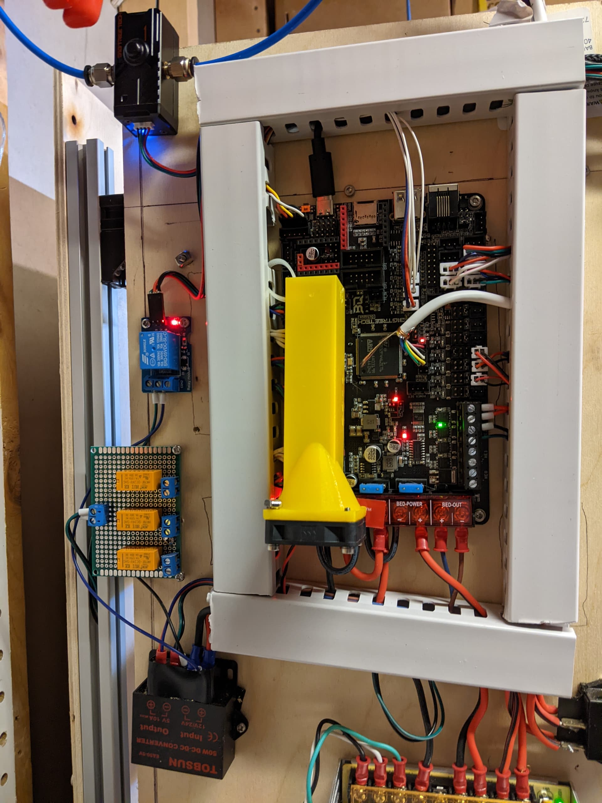
You are asking about the yellow wind tunnel? Yes, I made it when I was trying to find easy prints to test the v4 printer on and I have a pile of 5V 40 mm fans… the octopus has 24/12/5 V selectable fan outputs via jumpers, so I decided to make the wind tunnel to make sure the tmc drivers never overheat. I can’t say how good it is, but it gives some hope they won’t overheat easily.
Does the relay completely stop the bed from moving or does it just slow the decent? A slow move down wouldn’t be a problem at all. And then it would already be at the bottom before it powered up so the shift wouldn’t matter correct? Well I guess that wouldn’t be any help for a firmware restart. But I have gotten MUCH better at remembering to lower the bed all the way before doing that lol
I have not hooked up the motors to the relays yet because I want the relay behavior to be correct before I cut the motor wires in. Still don’t know if a pull-down resistor to ground on the signal pin is a good idea.
Typically if the pin is in a high-Z state, you should be fine with a 10k resistor to ground for most microcontrollers. However, if you’re referring to header J32 of the octopus board it looks like that pin has a 10k pullup resistor on it already, so your 10k to ground would form a voltage divider and end up with around 1.6v on that pin.