I would hold off. I’m thinking about a way that could work using a few external logic gates. I just haven’t figured it quite out yet.
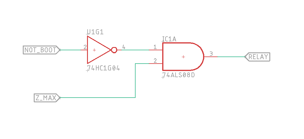
Do you have two pins that you can use for control? The Z_MAX and another pin (lets call it NOT_BOOTED)? If you built a small circuit with external boolean logic gates (AND, NOT, NAND, etc.) you could get around this delayed start issue. Set NOT_BOOTED low in your code. If NOT_BOOTED goes high, you know your device is booting, so you ignore the output of Z_MAX. If NOT_BOOTED goes low, you use the value of Z_MAX to set your relay on or off.
I think something like this:
It is on j32. Maybe use a different pin… I didn’t see that part of the schematic with the pull-up though and while a voltage divider would be helpful at the boot sequence, it would likely miss the trigger when we want it to switch with that in place…
I should have clarified: the 1.6v voltage divider would be a bad thing if this is a digital pin. You want either 0v or 3.3v on that pin, somewhere in the middle is bad for a digital input.
It is a digital output. It switches the relay,.
I was just about to edit my reply. You’re right, as an output it wouldn’t be bad for the octopus. But you wouldn’t want 1.6v on the input to your relay, for the same reason.
what if I move it to one of the fan outputs?
Sorry, once you pull in mosfets we are out of my league. I keep saying someday I will learn them, but I’m not there yet. It certainly wouldn’t hurt to attach a multimeter to ground and that fan pin to see what happens on startup, but I’m not sure what you’ll see.
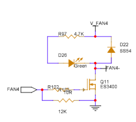
I’ll find another pin. After staring at the diagram in my previous post, it has high voltage tied to it and the fan4 output from the processor is likely in the wrong spot. It is pulse-width-modulated to apply part or all of the available power to the output pin at whatever the switched voltage is. I would think fan 4 would be on the switch line of the mosfet, not on the power leg. That diagram is wrong or I don’t understand it. There has to be one pin that is available that can be used.
don’t mosfets switch on the ground side? seems I remember that they are always 24v hot and ground switched
I do think if you find a second pin like the z_max pin, then you could do like I described here:
It would just take a couple of simple logic gates, or could be done with a microcontroller if that’s what you have on hand.
or I could just pull off R26 and the pullup wouldn’t pull up…
Ha! That’s a good point. Remove that pull up resistor. Good idea.
Just like transistors, there are different kinds of MOSFETs. N channel MOSFETs are the more common and switch the negative side. P channel MOSFETs switch the positive rail. You can get those as separate boards to change switching logic… but for 5V or less much easier to just use NOT logic.
1 Like
on the SPI3 plug (J74) PB3, PB4, PB5, PA15 are 4 direct to processor pins that should work for this. it cuts off the ability to expand with SPI, but it should work for our purposes as a z brake. the other option is USART1 on the tft header J70 or the EXP1 or EXP2 plug pins.
EDIT: ****** IT WORKS! ******** no custom firmware needed if you use J70 USART1 TX pin PA9 as the multipin. at power on, it remains off until the motors are enabled, then it flips on. On the octopus, this is a 5 pin jsh header. I modified the 3 pin header I was using for J32 (the endstop pin with the pullup) by swapping the power and signal wires and trimming off one of the 2 side guides on the actual connector so the 3 pin will fit in the 5 pin header.
[multi_pin z_enable]
pins: !PG5, PA9 #PG14

[stepper_z]
enable_pin: multi_pin:z_enable
step_pin: PF11
dir_pin: PG3
microsteps: 16
rotation_distance: 32
endstop_pin: probe:z_virtual_endstop
.
.
.
1 Like
Ok I’m going to splice in the steppers now because the relay triggers in each of the circumstances I believe it should.
Initial power up: brake on
Reboot: brake on
Initial home: brake off
Motor disable: brake on
Based on this photo @vicious1 shared it is the stepper black and green wires that get shorted together:

I don’t have anymore 4 pin stepper jsh plugs, so I’m going to splice in something else. I’ll report back once I have tested the brakes.
3 Likes
AWESOME!!!
I really dislike dupont connectors… I didn’t think the steppers are completely connected to the octopus board and so TC reports a problem. The relay switch isn’t fast enough when turning the brake off. Maybe a macro to catch G28 and enable the relays before the system homes X?
I’ve been debating making a mod.
I now have a formerly bad SKR pro 1.2 board which I’m working through issues and repairing as I go. This particular board fried a clamp connector where the fan outputs are. I was already planning to replace those. While I"m at it, I’ve been debating replacing the stepper connectors with some kind of clamp system, maybe Wago based.
I have earmarked this particular board to be a Klipper test board, and specifically intend to get this set up for testing along these same lines. I’m making slow progress on this as I have a bunch of goodies that arrived from V1E yesterday and spend most of yesterday down the rabbit hole doing various test and debug of things.
I do note that with the shrouds pulled off of the stepper connectors, the cables I have do fit better and seem to be happier being retained.
I just won an ebay bid of a v1E skr without the retainer clips. I’ve gotten pretty good at crimping jsh connectors, but my dupont crimping skills is ok until it has to go into the connector and the receptacle ones never go in as they should. The pin plug side you can grab with pliers and pull them through the little plastic holder until they clip into place, so I prefer to recrimp and put on jsh connections that snap in over the possibility of the dupont connectors working loose or not making contact at all. The connectors should be here in another day or so, which is why I’m not jumping to pull the plastic off the ones in place. Testing the system, TMC kicks a shorted error, so I don’t think it is switching fast enough. Maybe needs SSRs and that won’t be as economically favorable.