Just found this amazing item on AliExpress. Check it out! $2.03 47% Off | TZT 5V Relay 1 2 4 8 Channel For OMRON SSR High Low Level Solid State Relay Module 250V 2A For Arduino
$8.21 for an 8 way ssr relay. And they have it in high or low triggered.
SSR is the wrong type of relay for this. What he’s doing will work to some extent.
An active electronic brake would involve a fast SCR type response. Playing with such is on my to-do list, but it’s down there well below things like “Finish building my own repeat so I can test”
I lack the exposure the the speediest switching relay type, but solid state over magnetically moving metal flapper is likely the better option for speed. Is there one you could recommend I could get and try?
It’s not just about switching speed. You want an mechanical relay so you don’t have to deal with the electrical limitations of an SSR. The mechanical relay shuts off in a few hundred milliseconds. That is plenty fast enough.
If 1/3 a second of unarrested drop wrecks your bed or blows up your drivers, then the scheme won’t work for you.
To assess this further, do a test. unplug your z axis motors (all 3) from your controller. Short 1 coil of one stepper with a wire short or with your shorting relay. How hard to move is that stepper? Now short the other coil and repeat. How hard is it to move the stepper motor now?
Bonus tests: with Z steppers NOT plugged into the controller, move the bed tup o max Z. Secure the bed with something. Now short both coils on all three motors. make sure you have something to arrest a fall if it happens. Let the bed loose and see if and how fast it drops with all 6 coils shorted. I’ve made shorting connectors for this type of thing in the past. If this test crashes the bed hard, this scheme wont work for you. If it doesn’t, repeat with a Kg or two on the bed.
You need to account for the time needed for the relay to switch off and clear the short. Something like 200-300ms, maybe as short as 100ms. The TMCs can see the short otherwise. If not possible, then you’ll need to get the shunt resistance up to wherever the TMCs are happy.
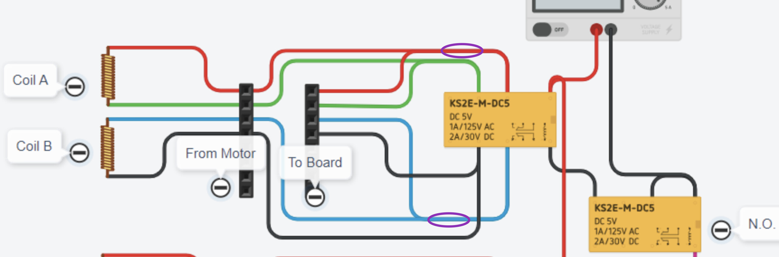
If needed, the shunt resistance would need to be out of the circuit when not shorted. Like this:
If Z falls at all it isn’t usable for print resume, so assume that isn’t a factor.
If you short both motor coils, back EMF presented to the board will be zero or so close to it as makes no difference no matter how fast it falls. (The board will be a load in parallel to a dead short as far as the EMF generator – your motor – is concerned.)
Most relays have both NO and NC poles, so you can further save your board by presenting an open circuit to it, even further reducing any back EMF exposure to the drivers and board. Simply wire the motor wire to common, the board to NO and the other side of the motor coil to NC. When the relay isn’t energized, the board sees an open circuit. As a bonus, the board never presents a short circuit to the stepper driver.
Electrically true, mechanically not true. It’s not good to thwack the bed on the bottom of the printer hard enough to cause damage.
This isn’t a good idea.
If the stepper coil wiring opens or closes when the driver happens to be energized, this is the same as plugging and unplugging the stepper motors while the controller and TMC2209s are powered up. That’s a great way to blow drivers.
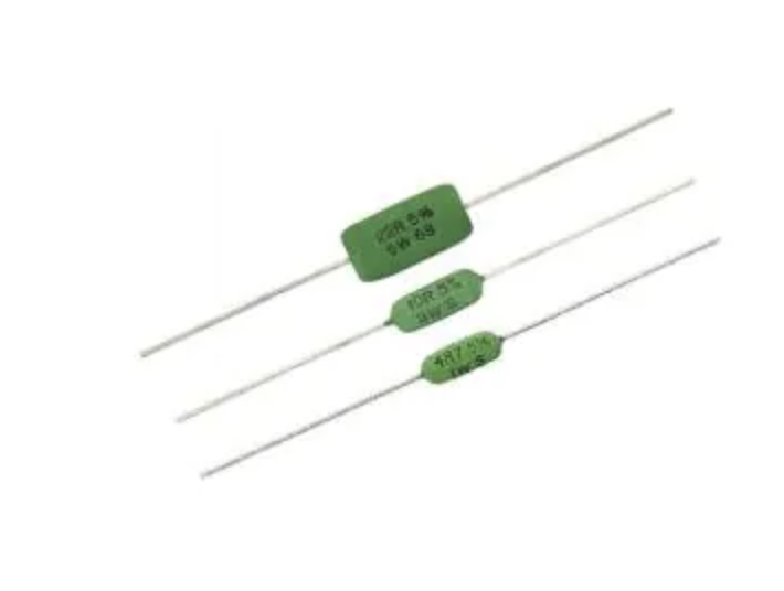
Yes, exactly. I had done a little looking into a candidate resistor a few weeks back, and these are an example of something that might be a simple option for wiring up a shunt. $2 each.
Edit to add- the shunt resistance is put in parallel with the coils, and it’s a trade off. Too little resistance and you get the TMCs detecting a short. Too much, and you don’t get effective braking action.
That’s why all the suggested tests above about viability. The same tests would apply with the shunt in place of a direct short.
It’s worth another read of the TMC2209 data sheet to refresh how they do the detection.
So how is it different to short circuit the motor coil than to open the circuit? In which case the whole idea for a brake is a bad idea. Since the default state of the relay is going to present either an open circuit or a short to the TMC drivers, both can cause problems if it happens while energized, unless you think the driver would survive unexpected dead short circuits while energized. I guess that’s not the same as unplugging a motor, but I can’t see that as good for anything.
The relay deactivating while the driver is engaged could be a problem, of course, as we add more components to the system we add more potential points of failure.
Of course, which is the other reason we want a brake, but if the bed will fall fast enough to cause damage with the brake engaged it would certainly also cause electrical havoc. Probably thjs means something else is either really badly designed (3/4" plate steel bed support, lol) or else is already broken. At the very least, it means that we don’t need to worry about back EMF while the relay is engaged
I assert we don’t want a dead short, but rather a manageable shunt resistance. Something roughly in line with the nominal coil resistance. A suitable value is high enough resistance that it wouldn’t trip the overcurrent/fault protection of the TMC. It is also low enough resistance that it provides torque braking when the motor tries to move. The range is probably somewhere above an ohm, and below somewhere around 5 ohms. Hence my guess of 2.2 ohms above as a candidate value.
Edit to add- placing this shunt value in parallel with the existing coil load shouldn’t present the make/break inrushes or collapses that you get with going open circuit or closing an energized circuit- the stepper motor coils would always be in the circuit, it’s just the shunt/brake resistor that comes/goes.
Edit 2- all of this is for the ‘simple’ version using a relay. The more complicated version would use something like an SCR to respond if the voltage on the coil goes above the danger threshold for blowing the drivers or voltage regulators on the controller. I think there’s a chance the shunt approach is workable with the right value of shunt.
if it is back EMF, couldn’t we “just” engage a clamping circuit with the relay (not that I know what this circuit looks like), so it can’t exceed x voltage that will damage the driver?