Update on Primo J in VA - Question on dialing in accurate cuts

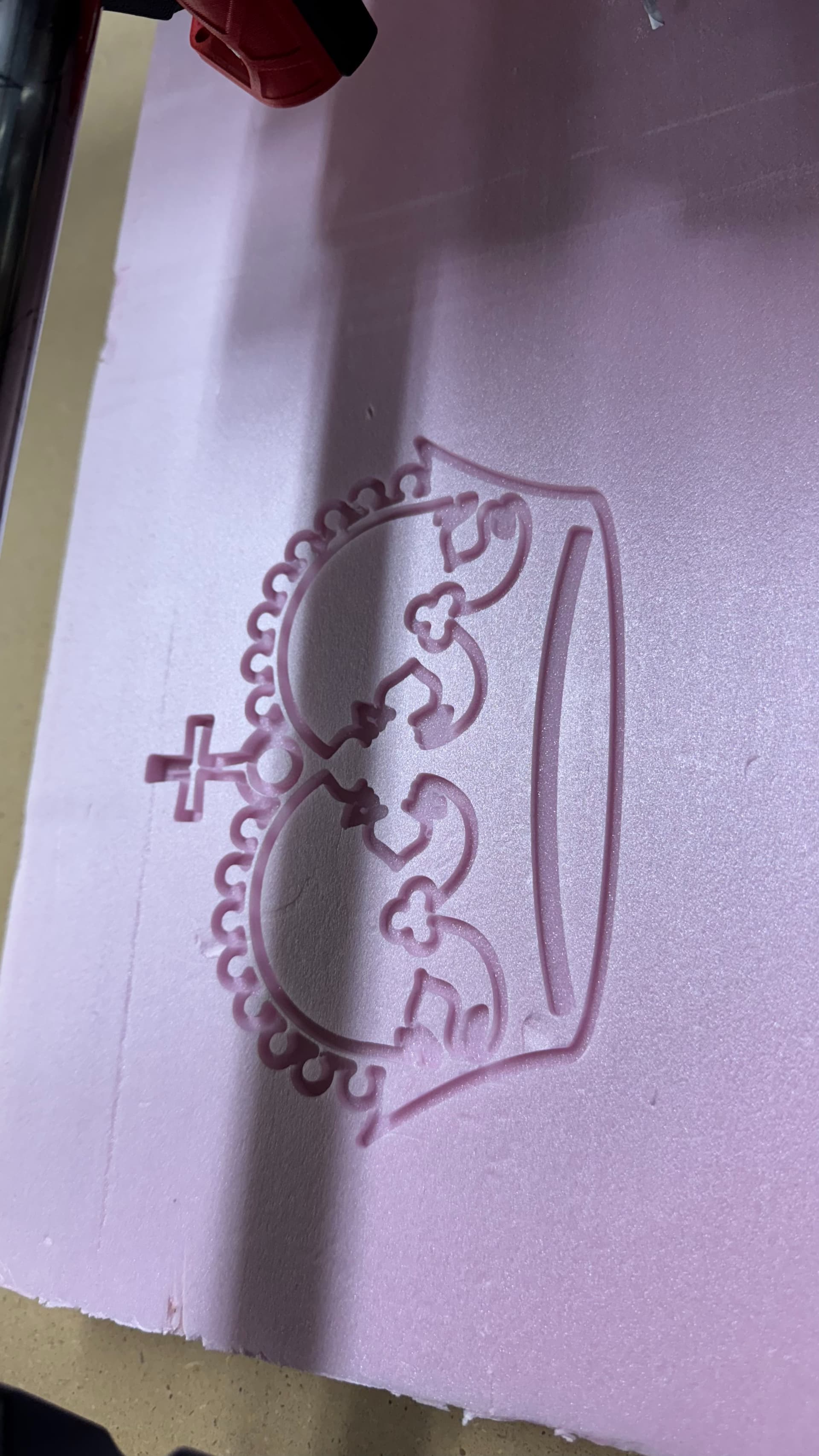
Started my Primo build over 2 years ago. Got it to the point of drawing the crown in December of 2022, and shared my progress here:

Since then I stalled hard on the cable management and enclosure stuff, and it gathered dust behind my table saw sitting on a couple sawhorses, and made me sad every time I walked past it.

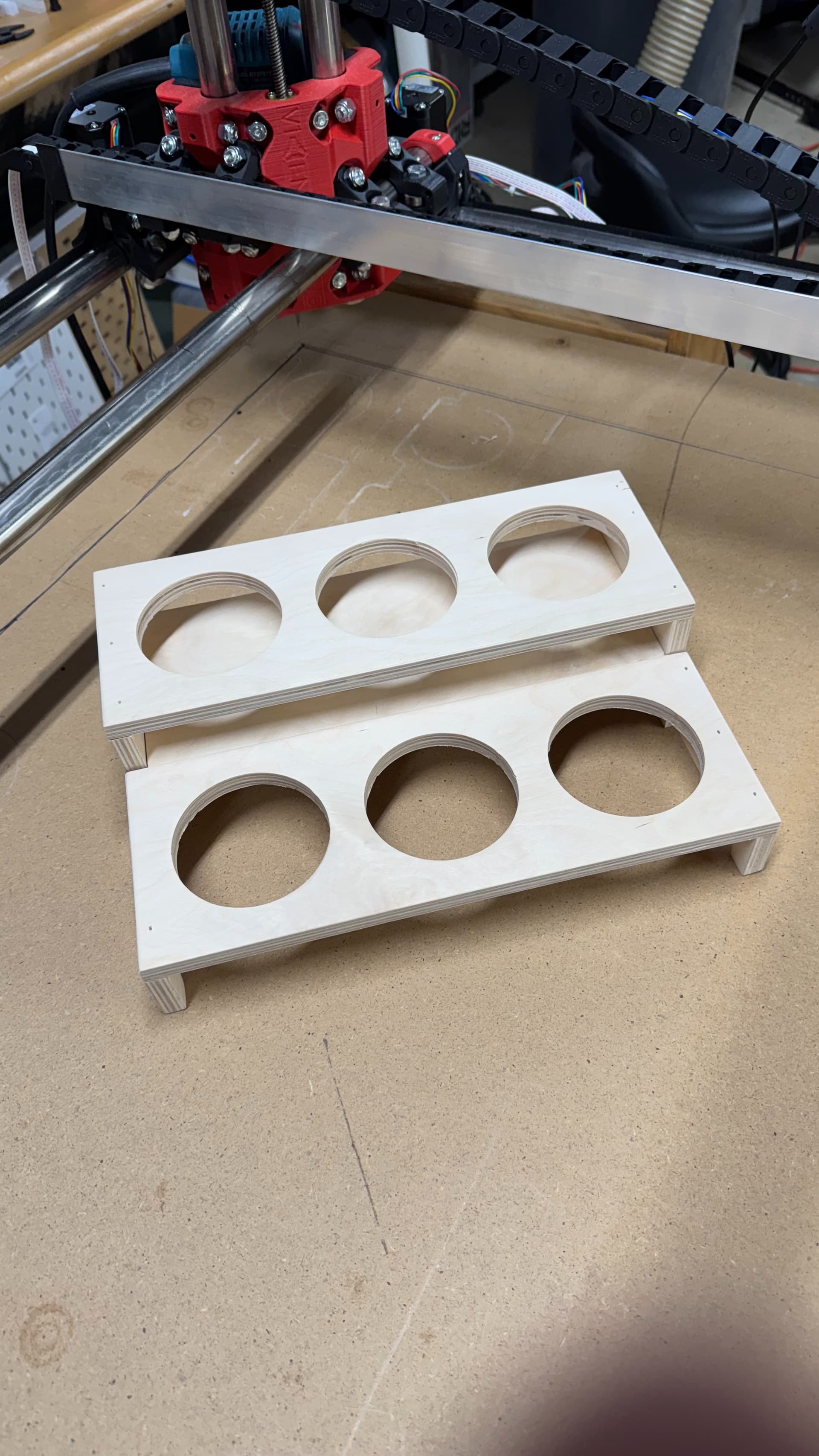
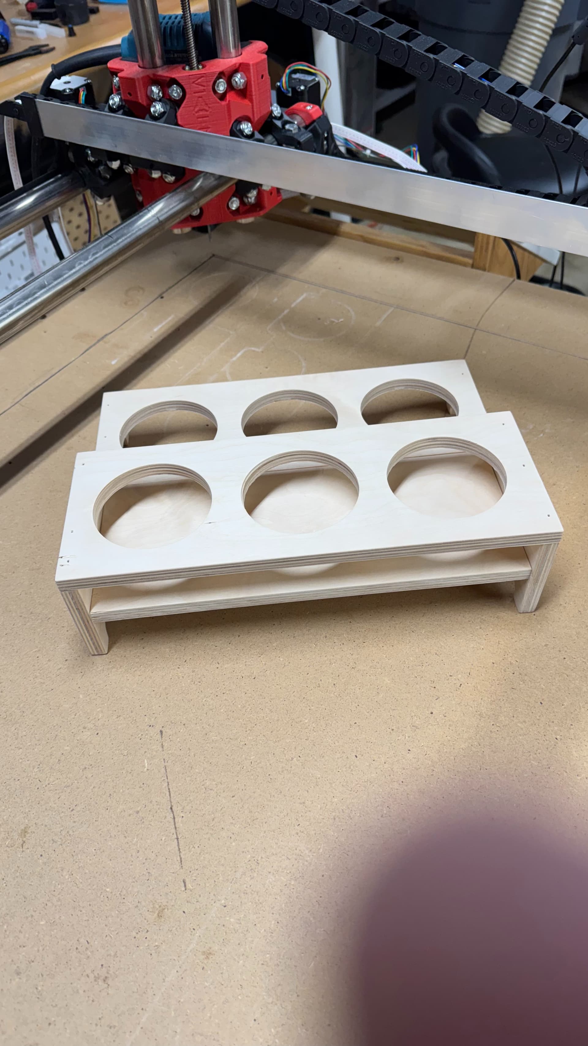
Much like 2 years ago, with some time off for the holidays, I decided to tackle making some basic legs for the table, so I could get my sawhorses back, and move it around to get it out of the way when needed.

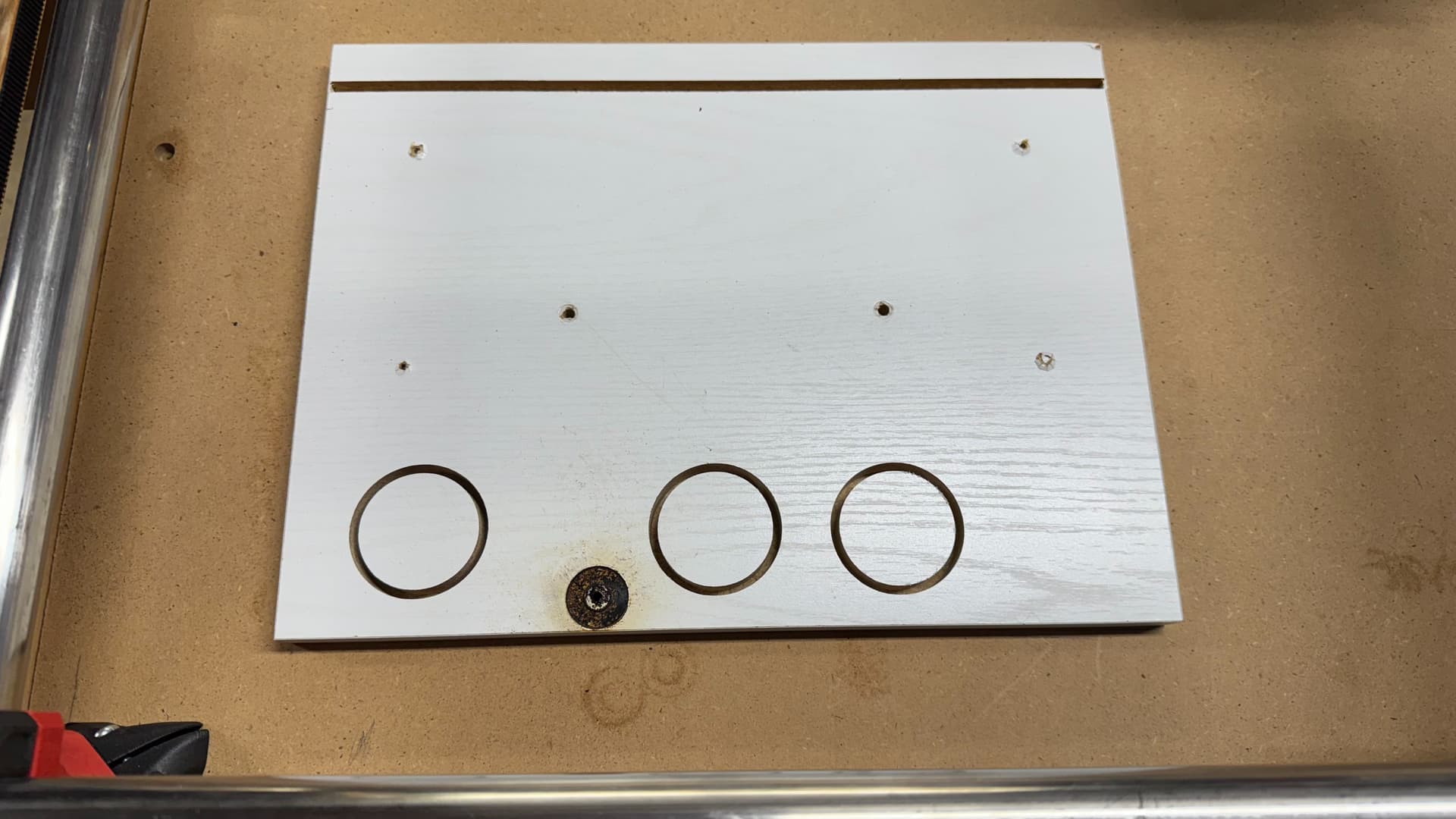
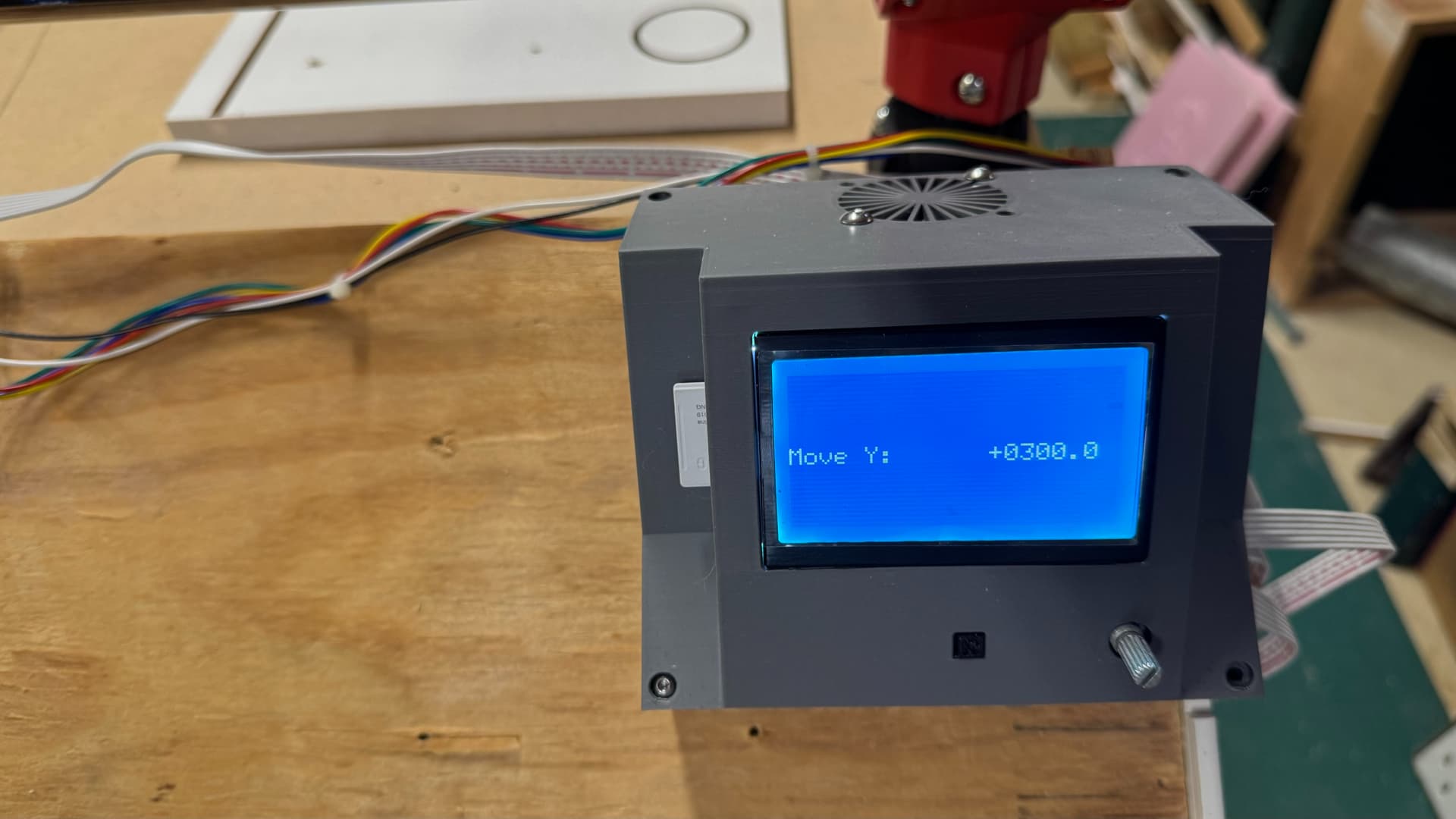
Having finished that task, I was motivated to get it re-wired, get the board and screen in the initial enclosure, and running again. I was able to finally get to the point of cutting, first with some extruded pink foam, and then my last test of the day was cutting a circle in melamine coated particle board (leftover shelf parts).

It’s really exciting to finally be making chips with this!

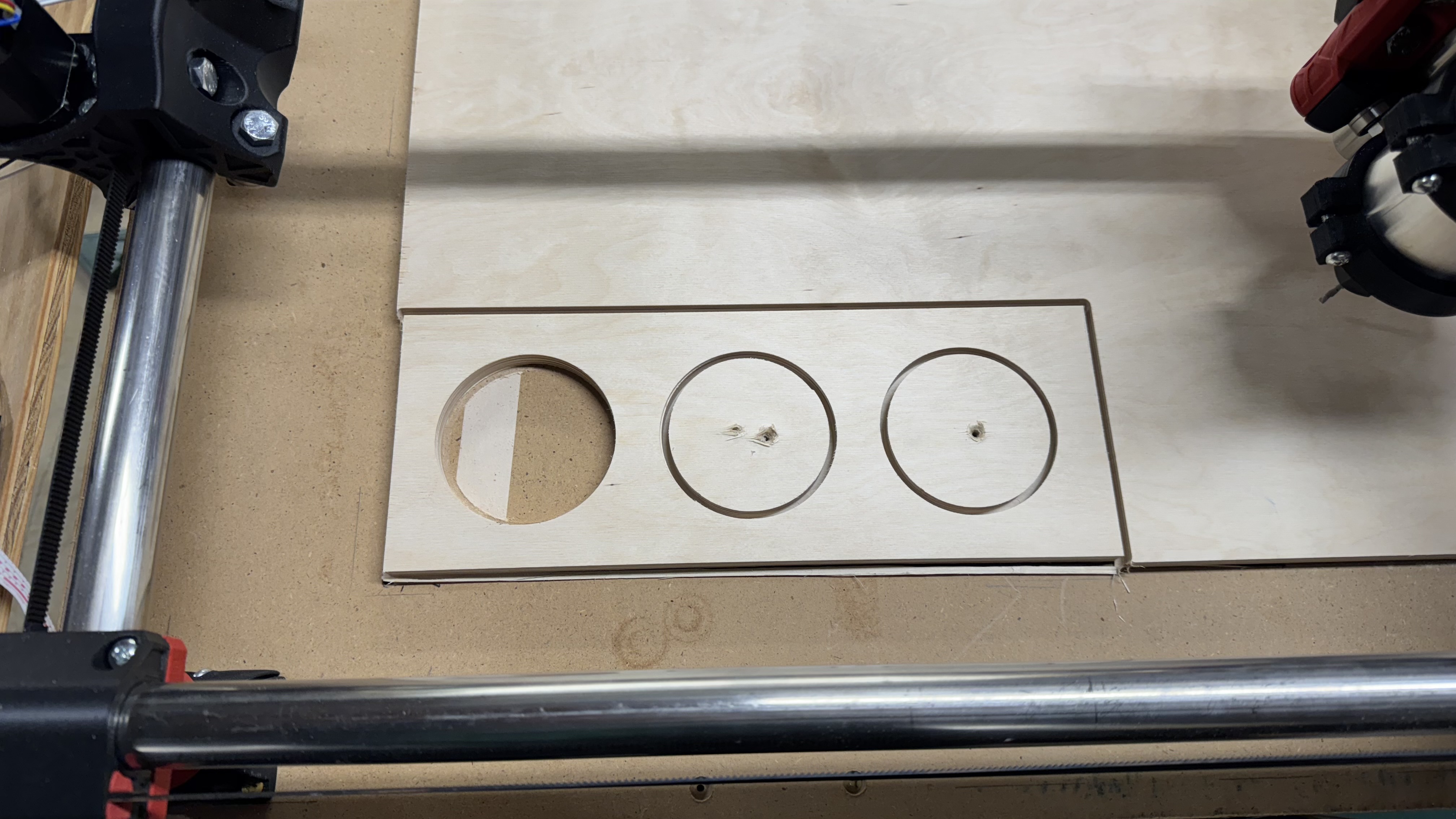
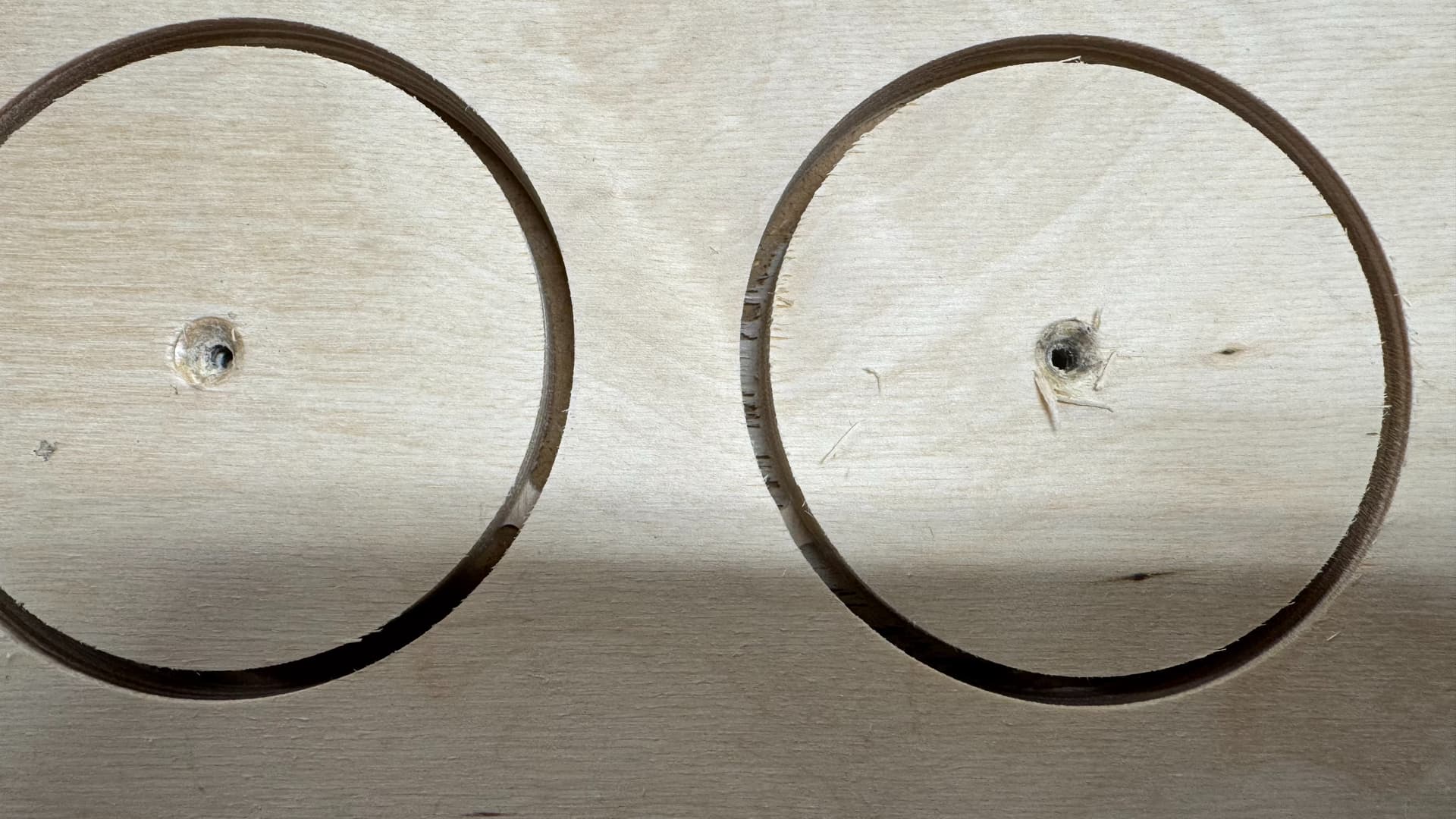
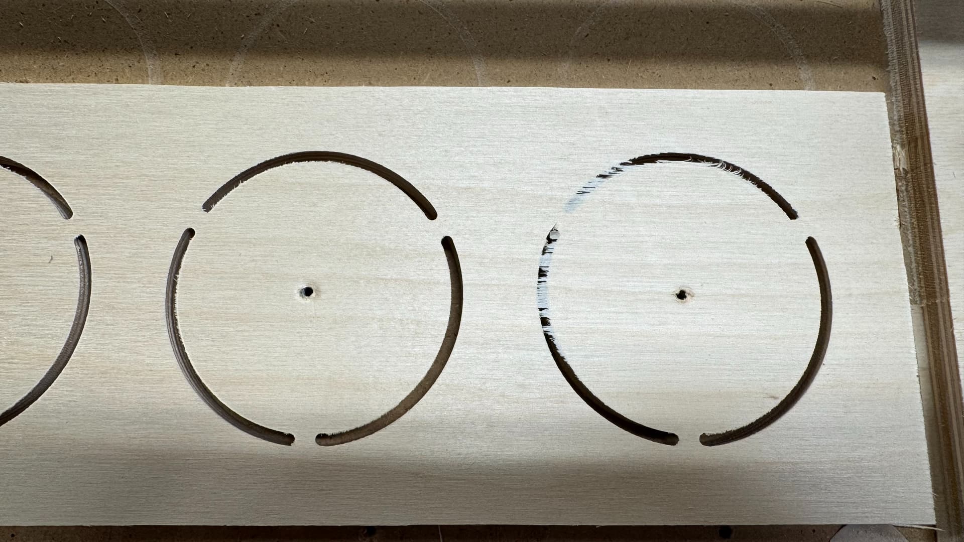
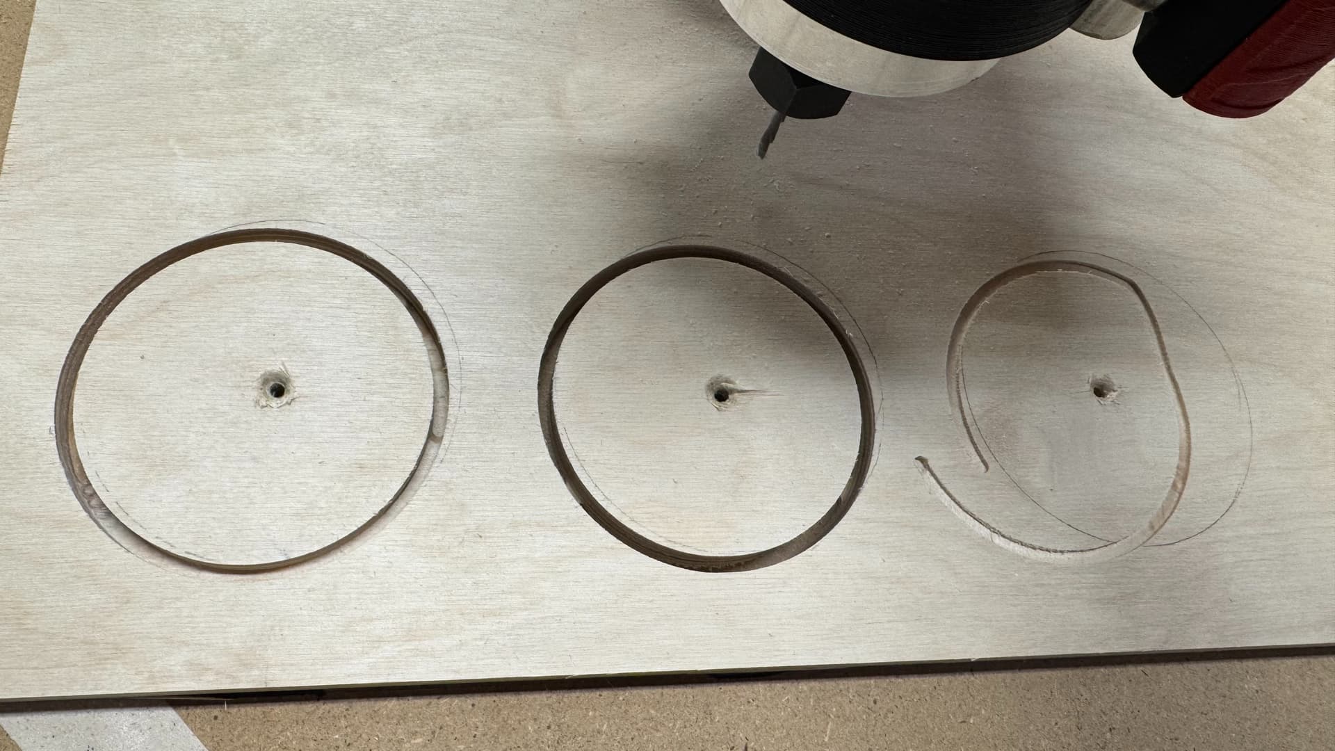
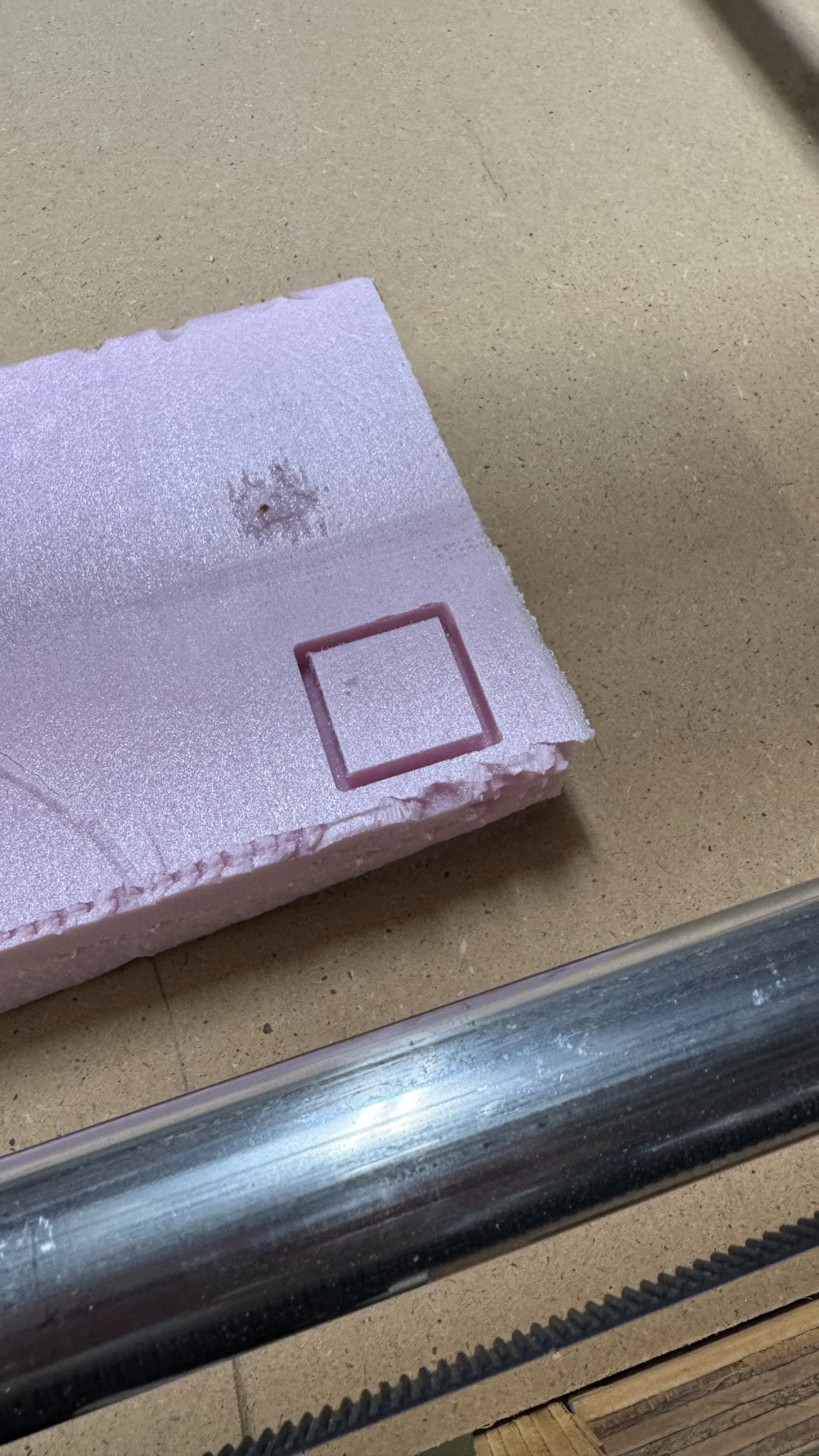
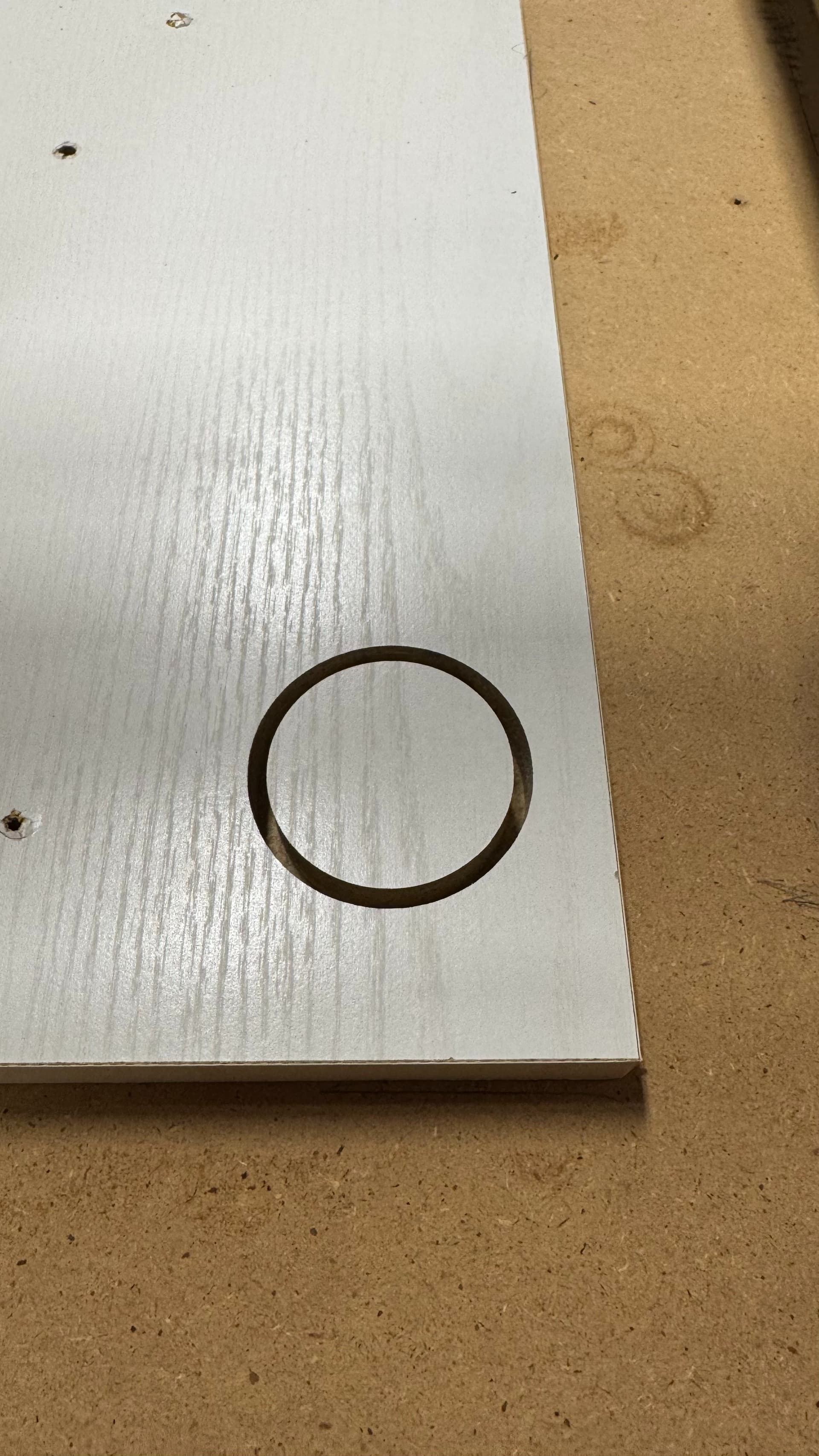
The last image shows a 50mm circle that I created in Inkscape, and used EstlCAM to create gcode for, to cut as a hole, so the outer diameter of the cut should be 50mm (I used 3mm as the width of the endmill, which I verified with digital calipers). The circle is just slightly off, slightly over 51mm in the Y direction, and just under 51mm in the X.

Where should I start in trying to dial this in more accurately? Should I try cutting a specific length in both X and Y and adjusting e-steps like I would with an extruder on a printer? Or is something else a better starting point?

For my first projects, this is already plenty accurate, and the cuts came out very clean, though the crown had some messy parts simply because it was scaled too small for the detailed parts to work with a 3mm end mill.

But for future projects, I may want better than 1mm accuracy at a 50mm scale.

Thanks in advance for any tips.

1 Like

Congratulations not only on getting your machine completed, but also in your persistence!

How repeatable is it?
Have you checked (and double checked) that your grub screws are tight?

1 Like

Good questions. I’ll check the grub screws tomorrow (well, later today), and run another pass at the circle and see if it comes out the same.

Are the belts equally tight? If they are too loose or too tight accuracy might be off as well.

1 Like

Well, it’s been sitting for two years, so the potential for belt stretch is certainly there.

I’ll look over the docs again to see if I can find the info on proper tensioning. Though if you have a link handy for the relevant info, that would be great!

1 Like

I don’t really. There are no definite values. :sweat_smile:

Haven’t had a chance to re-cut the circle, but I checked all the grub screws on the steppers, and they’re all still tight.

High repeatability. I cut two more circles (after an unfortunate crash due to selecting the wrong gcode file…need to clear all the 3D printing stuff off this card!), and all 3 circles are within less than 0.1mm of one another, closer to 0.05mm, and I think that’s getting pretty close to within the margin of error of my ability to measure consistently with my digital calipers.

PS - Do NOT recommend plunging all the way into melamine-coated particle board…the smell is NASTY. Also a reminder to get my emergency stop button wired up ASAP. Was able to hit the panic button on my enclosure and ensure no further movement, but had to manually turn off the router which wasn’t great. Thankfully, no apparent damage to the CNC, router, or end mill. My beard still smells of smoke, however.

That means you had a learning day in the shop!

Hopefully one of the MPCNC experts will chime in, slightly over 51mm in Y and slightly under 51mm in X is a strange stack up of error for me.

Oh, and here’s a pic of the enclosure…the panic button helped prevent further damage when I started the wrong gcode:

Indeed. And very grateful that it was an inexpensive lesson, as these things go…

I might want to try experimenting with a drag knife or something else that is effectively zero line width, to see if maybe the issue is a tool clearance issue. Although my end mill measures 3mm on my calipers, if there’s some vibration or other issues causing the effective diameter to be larger, that might explain the result. As I recall, my results when drawing a box using either sharpie or pencil were pretty much spot-on, but those were smaller (20-30mm per side), so would have been harder to discern any deviation.

What i would recommend is plunging with a 10° ramp or more or better: use a vbit with a really sharp tip use some masking tape and re-square your machine/ make some points also in x/y and measure the length using the centimeters side of the tape measure beginning at 10cms (tape it down and measure your second point minus 10 should be the final number in cms just convert to mm and check, if the x/y measurements are correct check your squaring

CNC newb…I’ve seen the ramp config in EstlCAM, but I’m not sure what that translates to in real-world terms…can you explain, or point me to somewhere that I can ramp up on that and similar terminology?

Good suggestion on the vbit…pretty sure I bought one in my initial bunch of stuff, so I should have one that’s brand-new, and would definitely be helpful here.

The ramp just makes sure you dont plunge straight to the material and prevents any bit deflection for aggressive z movements.

Found a good video that let me get my head around the ramping:

In the case of my mistake, it’s a moot point, because the cause was an incorrect gcode file, but I will definitely adjust my EstlCAM settings to include a more gentle ramp when cutting.

So, it turns out that after all the checking and whatnot, the accuracy issue wasn’t the CNC at all. It was the end mill diameter.

I measured it using my digital calipers, and assumed it was the same tip to tip. Turns out, all I had to do was read the case it came in.

What I thought was a 3mm end mill was actually 3.175mm.

After correcting that in Estlcam, I’m within less than half a millimeter of my target dimensions, which is good enough for my needs.

Grabbed some half inch Baltic birch from Woodcraft this evening and started my first simple project:

Aside from a hiccup with incorrect tab settings and not quite enough cut depth, I’m happy with the result. Need to make another one of these and then draw up and cut the other parts, but since those will all be simple, I’ll likely just use my normal woodworking tools for them.

I’m going slowly to start with (10mm/sec feed rate and 1mm depth of cut), so it’s definitely not the optimal way to cut out a rectangle.

Oh, and I used the end mill to cut a shallow channel along the 0 x and y limits in my MDF bed, and put my framing square on it. Pretty much dead on square.

I think I’m gonna need to double up on ear pro…ear plugs alone aren’t cutting it, between the CNC and the shop vac and shop air cleaner all running.

1 Like

I made a box/silencer for my shopvac. It was unbearable before

Yeah, I have a JET cyclone dust collector that’s much quieter, I just don’t currently have that set up in a way that it’s easy to use with the CNC. Proper distributed dust collection is on my (lengthy) shop to-do list, but I’m planning to move my shop to a different part of the basement in the not-too-distant future, so for now, shop vac it is.

Managed to dial in the tabs pretty well. Height of 1.5mm and 5mm length seems to provide more than enough hold, while still being easy to remove, and also gives me a little wiggle room since I’m still manually setting Z height before a job.


Accuracy was OK, given that I had to restart the earlier job, and wasn’t able to precisely keep the zero because the board rebooted, and the second shelf (well, second attempt at the second shelf) I zeroed the Y such that one edge was not getting cut…less dust, but it meant the width of that one was just slightly off.

Had my first “oops” moment of not realizing that the cutting path was outside the bounds of my machine, so that ruined one part, but nothing broken, so a good learning experience.

Decided that I’m going to change over from the RAMBO to a Jackpot board. The click knob is just way too fiddly for moving the tool head around, something that I rarely had to do on any of my similarly equipped 3D printers, so it wasn’t a big deal. With the MPCNC it’s a pain. Yeah, I can plug the board into my PC via USB and use Pronterface to move things around in a similar way to the web UI for the Jackpot, but every time I plug in the USB, the board reboots, so I lose my zero.

Once I get the Jackpot and accessories, I can get my e-stop wired up, put the various parts in a more proper enclosure, and tidy up the wiring.

Project complete, apart from adding finish (haven’t decided if I’m going to go with a clear coat, or paint, possibly the latter since unfortunately some of my brad nails blew out the side when I was assembling it.

Good opportunity for me to learn to combine CNC and traditional workflow (support shelf in the back was cut using table saw and miter saw). There are things I’d try to improve if I was doing it again, but I’m pretty happy with the final result:


And I just realized that I did not take a good pic showing the side detail, which was part of why I was inspired to use this as my first CNC project, so here’s a bonus screenshot of the side sketch in Fusion 360:

Workflow was designing the profiles as individual sketches in Fusion 360, exporting as DXF, then importing into Estlcad and setting up the paths and such. Not at all seamless, particularly since Fusion 360 is on my Mac Mini 2 flights up from my old Surface Pro that I’ve dedicated to the CNC where I have Estlcam installed, but it worked fine. Sneakernet, FTW!

For the sides, I used Inkscape to import the DXF from F360 and copy/mirror the first side to make the second, since I wanted to keep the same “nice” side of the baltic birch for both outside faces…won’t matter if I paint it, but may matter if I clear coat.

A downside of Inkscape is that I’m not yet good enough with it to keep the scale correct. If I open a DXF that’s straight from Fusion using Estlcam, it’s the correct size right away, and no need to resize. If I make a drawing in Inkscape, or open the DXF from Fusion using Inkscape, it ends up needing to be resized once I bring it into Estlcam. Not a big deal, but it is an extra step.

Anyway, hopefully if anyone else is in the spot I was (MPCNC moving and drawing, but not cutting), I hope this will inspire you to get that router mounted and make some chips!

6 Likes