This looks like you have the tool defined as being smaller than it is really cutting.
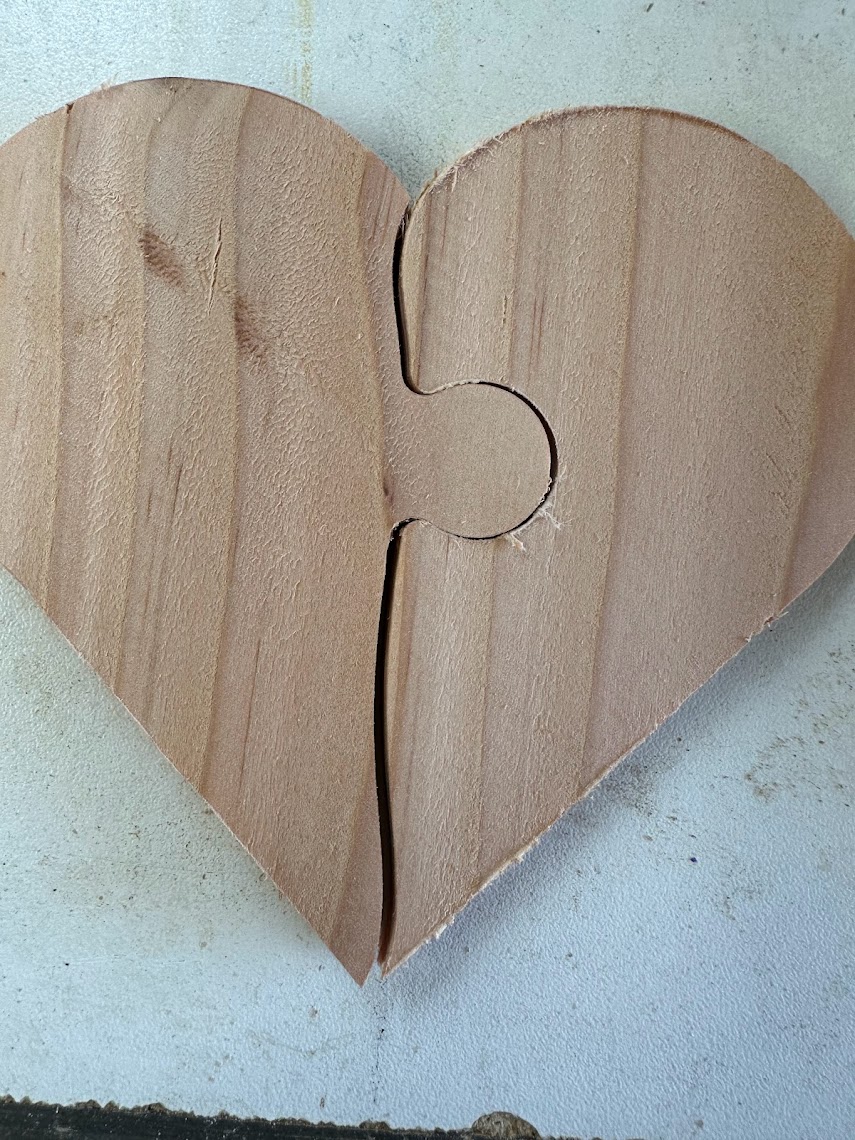
The first time I tried to get something close fitting like that, it wouldn’t go together at all, the tabs were too big and the openings too small. I altered the bit cutting dimensions to a smaller diameter, until it worked out, and I got accurate sizing for parts.
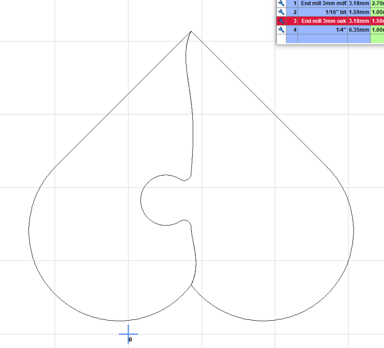
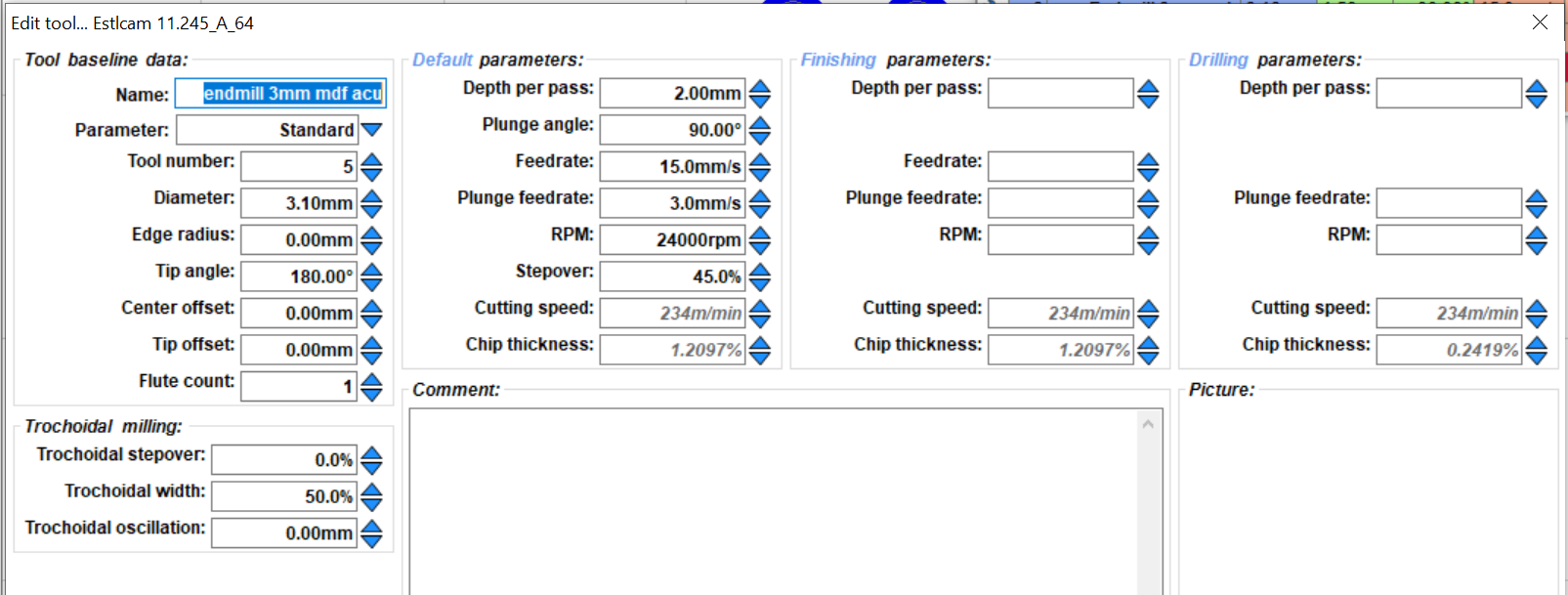
this looks like the opposite. I see you have the bit defined as 3.18mm (1/8") but it looks like a larger bit is actually in the machine, or else something is happening that is making the cut wider than you have defined.
I cut some slots in material at 0°, 45° and 90° and measured them with calipers. They came out consistently at a hair under 3.00mm. i defined the bit as being 3mm (Still making the tabs just a bit big and the slots a bit small) and I get a nice pressure fit.
I think you are on to something but not sure what my data is telling me. I tried to cut the outside (part) a 25.4mm x 25.4mm square. It doesn’t measure 25.4mm for me.
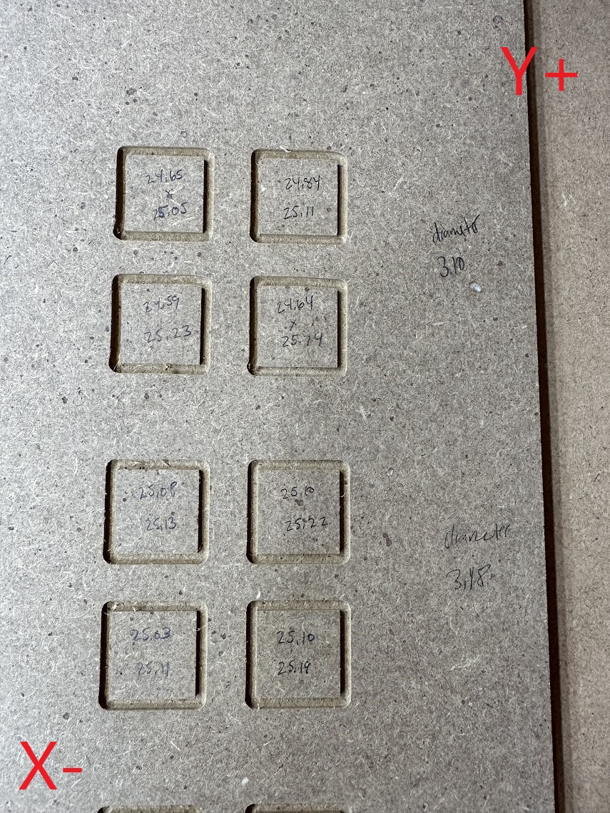
After measuring single passes, I get ~3.10mm for tool diameter. I compared 3.18 to 3.10 by drawing 4 boxes, 2mm deep, single pass. Measurements are X by Y. So horizontally measured is the top number, then vertically is the bottom number.
Can you double check if you are doing conventional milling or climb milling? You should be doing climb milling.
My guess is that you are doing conventional milling, and it causes the tool to deflect into your workpiece, taking away too much material. This is in some ways equivalent to a larger tool that is not deflecting, except that it’s not consistent.
Climb milling will cause the tool to deflect away from your workpiece, leaving a little bit of extra material behind. A finishing pass, slow and full depth, will remove this extra material and leave very good dimensional accuracy because only a small amount of material is being removed, so the loads are very light and there is very little deflection.
I take my finish passes in conventional because they are very light load and I like the surface they leave.
How much deflection they cause is going to be a factor of machine rigidty, depth of cut, stepover, and bit geometry.
I definitely noticed SOME difference in part dimensions, although not as much as you have in your puzzle.
I think what Dan is getting at is that your bit should be defined as whatever you’re measuring the single-pass slot, although I could be wrong because if your material is springing back that would make the slot undersized. I do this in MDF, because it tends to not do that.
But it looks to me like that will make your squares even smaller. But still, 0.5mm is very close, I’ve gotten a fair amount of movement by tightening my belts, so check those. I clamp a dial indicator on the machine, move the truck away, then into it until it registers, zero it, then call for a 10mm move and tighten/loosen until I get ten mm. I make sure I’m moving the same directiom I’m measuring before resetting the indicator ensures that whatever fraction of a mm contributed by backlash isn’t part of the measurement. If you have a very good ruler, you can also tape something pointy like a BBQ skewer to the truck and point it at the ruler (tip I learned here).
I could not leave it be and stumbled upon this while reading about conventional and climb again…
A quick rule of thumb is to check your offcut. If your offcut has a nicer finish than the part, rotate around the other way and the better finish will be on your part.
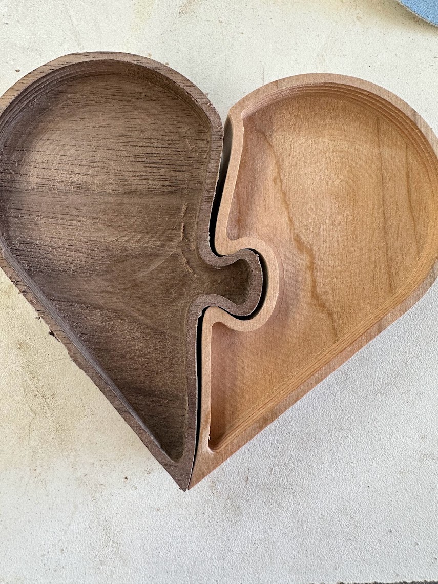
Climb milling did make the machine slightly more accurate. I am still at ~25.8mm - 25.5mm which seems to be too much error for an interlocking puzzle piece.
I also tighten the adjustment bolts on the core. I noticed the bottom was kicking out sometimes.
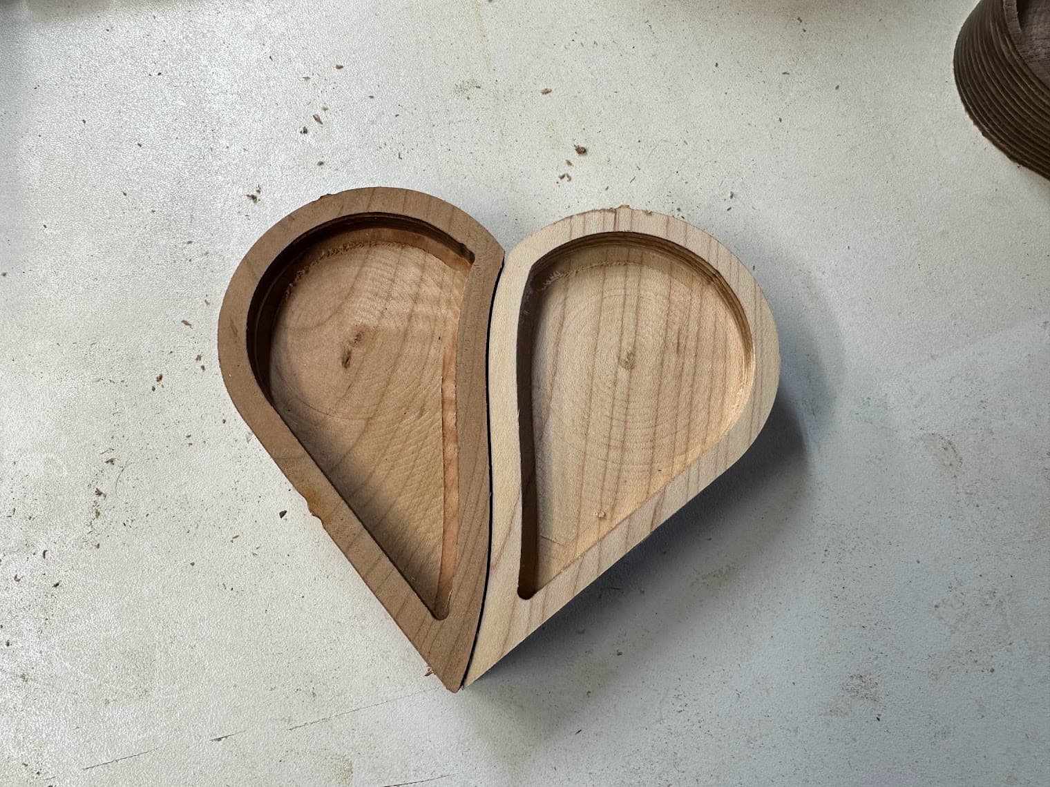
I think I am going to move onto something else. I don’t really enjoy trying to dial the machine in to be this accurate. I feel like I am asking for too much. I am going to modify the design to not interlock
Here is the heart dxf file I was using (edit: at 50% scale). There is no offset between the halves, which might be part of my problem. I figured if I parted both sides, it should fit perfectly. heart v2.dxf (6.3 KB)
I bought some of the 1/8" Single Flute Carbide Endmills from the shop (and some others). I will retry my tests with those since we know they are 3.18. It will be helpful to eliminate some variables.
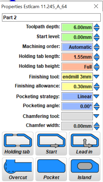
Another thing that can make a difference is the finishing pass fields are blank, meaning they will use the default parameters.
I would suggest depth per pass as 12mm (or any value greater than 6 mm will make a single full-depth pass) and feed rate much slower, perhaps 5 mm/s or so, or even less if you don’t mind waiting.
I don’t think you’re asking too much for precision in the range of about 0.1 mm, but there is a tradeoff between speed/depth and accuracy. By hogging out most of the material at higher speed with a finishing allowance and finishing the last bit at low speed, you can get the best of both.
Phil, you gotta remember that not everyone has the centuries of engineering excellence to live up to that you do. Some of us were lucky to escape the trailer park (some may not have even been that lucky), where solid engineering involves duct tape, whatever cast-off boxes are lying about, and blue tarp (you know it’s high quality work when the tarp is blue).
Moving the goalposts is one of our grand traditions!